

(Figure 1)
(Figure 2)
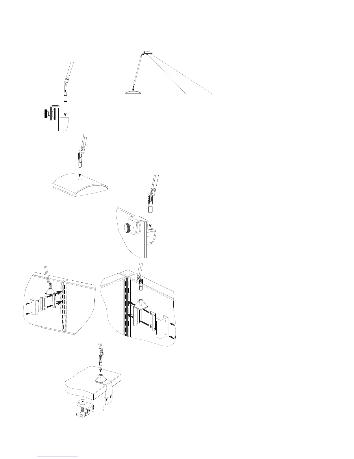
TINO™ PRODUCT INSTRUCTIONS
TINO™ should be mounted or placed 1’
behind the desktop location you desire to
illuminate.
Assembling Arm to Divider Mount
1. Apply pressure near the top of the bushing.
2. (Fig. 1) Insert Arm base into divider mount.
Assembling Arm to Free Standing Base
1. Apply pressure near the top of the bushing.
2. (Fig. 2) Insert Arm base into Free standing mount.
(Figure 6)
(Figure 3)
(Figure 4) (Figure 5)
Fastening the Divider Mount
1. Open the divider mount by rotating the knob counter
clockwise to an appropriate size.
2. (Fig. 3) With care place divider mount into divider.
Panel Mount Installation (Fig. 4 & 5):
1. For in-line panel (Fig. 4), insert the teeth of bracket
through the center slot of the panel bracket.
2. For corner panel (Fig. 5), remove screws and rotate
the bracket cover so that the screw holes will be on
the opposite side. Reattach and Insert the teeth of
bracket through the outer slot of the panel bracket.
3. While holding the screws in, Insert the teeth into the
slotted standard and press downward insuring the
teeth are fully hooked over the slots.
4. Tighten screws alternately using a 3/32 Hex Driver
until bracket is securely tight on panel
Clamp Mount Installation (Fig. 6)
1. Slide the base bracket between the panel and the
work surface.
2. Unscrew the knob on adjuster bracket to the lowest
position and insert into slots on base bracket.
3. Tighten knob against bottom of work surface
16518.000.000 Rev. B
(Figure 7)
(Figure 8)
(Figure 9)
TINO PRODUCT INSTRUCTIONS
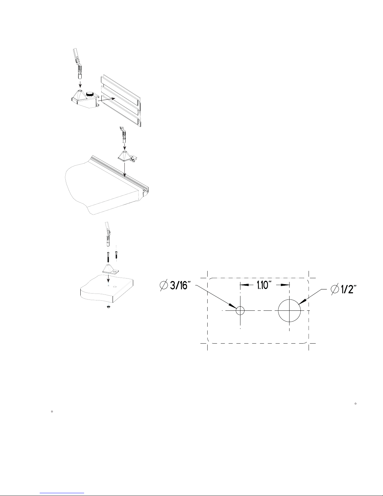
Slatwall Mount Installation (Fig. 7)
1. Twist the tension knob, positioning the hooks to fi t over a single slatwall rail.
2. Hook the top bracket hook over the slatwall rail.
3. Position the lower hook under the slatwall rail
4. Tighten the tension knob, securing the mount to the slatwall.
Rail Mount Installation (Fig. 8)
1. Position the T-nut at the tip of the screw.
2. Aline the T-nut to fi t into the rail
3. Insert the bracket into the rail.
4. Hold the bracket fl ush against the rail.
5. Tighten the screw using a 3/32 Hex Driver, ensuring the T-nut
turns and locks into the rail.
Surface Mount Installation (Fig. 9)
1. Drill Holes in work surface using the template (fi g. 10)
2. Insert the cap screw though the mounting bracket and smaller hole
in the work surface.
- Use the shorter 1 ½” screw for work surfaces ½” to 1” thick
- Use the longer 2” screw for work surfaces 1 1/8” to 1 1/5” thick
3. Aline the larger cord hole in the plate with the larger hole in the work
surface.
4. Screw the fl ange nut onto the screw under the work surface.
5. Tighten using a 9/64” Hex Driver and an 11/32” wrench.
6. Thread the power cord down through the larger cord hole.
Occupancy Sensor:
The under-head integrated passive infared (PIR) occupancy sensor automatically turns the fi xture off after 30 minutes of no detection. Coverage: 360
lens view, 90
Touch and Hold Dimming:
Any level of output can be achieved for user preferences, from 100% to 15% light output, with a touch and hold of the fi
sensitive button under the head, releasing when desired level is reached. On/Off is toggled with a single touch.
outward detection angle, coverage of 30” diameter at 15” distance.
(Figure 10)
nger on the slightly raised touch
16518.000.000 Rev. B

MONITOR MOUNT INSTRUCTIONS
(Figure. 1)
(Figure. 2)
Determine Right Hand or Left Hand Mount
1. Right Hand Position Shipped Standard. (Fig. 1)
2. Flip lamp base to re-orient for Le Hand. (Fig. 2)
(A)
(B)
(Figure. 3)
(Figure. 4)
Positioning and Attachment of Monitor Mount to Monitor Arm
1. Choose (A) upper posi
tion or (B) lower position.
2. Insert screws into holes and tighten. (Fig. 3)
3. Place monitor arm on moun
t plate lining up screw holes. (Fig. 4)
4. Insert proper screws and tighten.
5. Slide inner mount arm and base monitor mount even with monitor edge and tighten screw. Refer to (Fig. 3) for positioning.
Occupancy Sensor:
The under-head integrated passive infrared (PIR) occupancy sensor automatically turns the fixture off after 30 minutes of no
detection. Coverage: 360 lens view, 90 outward detection angle, coverage of 30” diameter at 15” distance.
Touch and Hold Dimming:
Any level of output can be achieved for user preferences, from 100% to 15% light output, with a touch and hold of the finger on the
slightly raised touch sensitive button under the head, releasing when desired level is reached. On/Off is toggled with a single touch.
SPECIAL NOTE: Before installing your Monitor Mount, read the safety instructions that shipped with your monitor arm to ensure equipment weight ratings do not exceed[the
Monitor Mount and Tino Light weigh 1.2 lbs. combined].
CAUTION: Use Display weight, hole pattern, and Monitor Arm specifications to determine compatibility with the Monitor Mount.
CAUTION: Th e Monitor Mount is intended for use with most 15”-27” standard Monitors or Displays. It is length adjustable through a range that supports said sizes.
CAUTION: Use appropriate mounting hardware to attach Light Corp Monitor Mount. Longer screws may be required to meet Monitor Arm manufacturer’s specifications.
CAUTION: Monitor Mount is not recommended for use with Freestanding Monitors.
CAUTION: Do not use Monitor Mount for Monitor Arm movement or adjustment.
CAUTION: Light Corp Monitor Mount is intended for use with VESA standard mounting patterns (100mm x 100mm and 75mm x 75mm).
CAUTION: Light Corporation disclaims liability for damage to mounts, adapters, displays, monitors, monitor arms, other property or personal injury resulting, in whole or in
part, from improper installation, modification, use or misuse of its products.
17113.000.000 Rev B
 Loading...