

REED PREMIER
MOUNTING INSTRUCTIONS
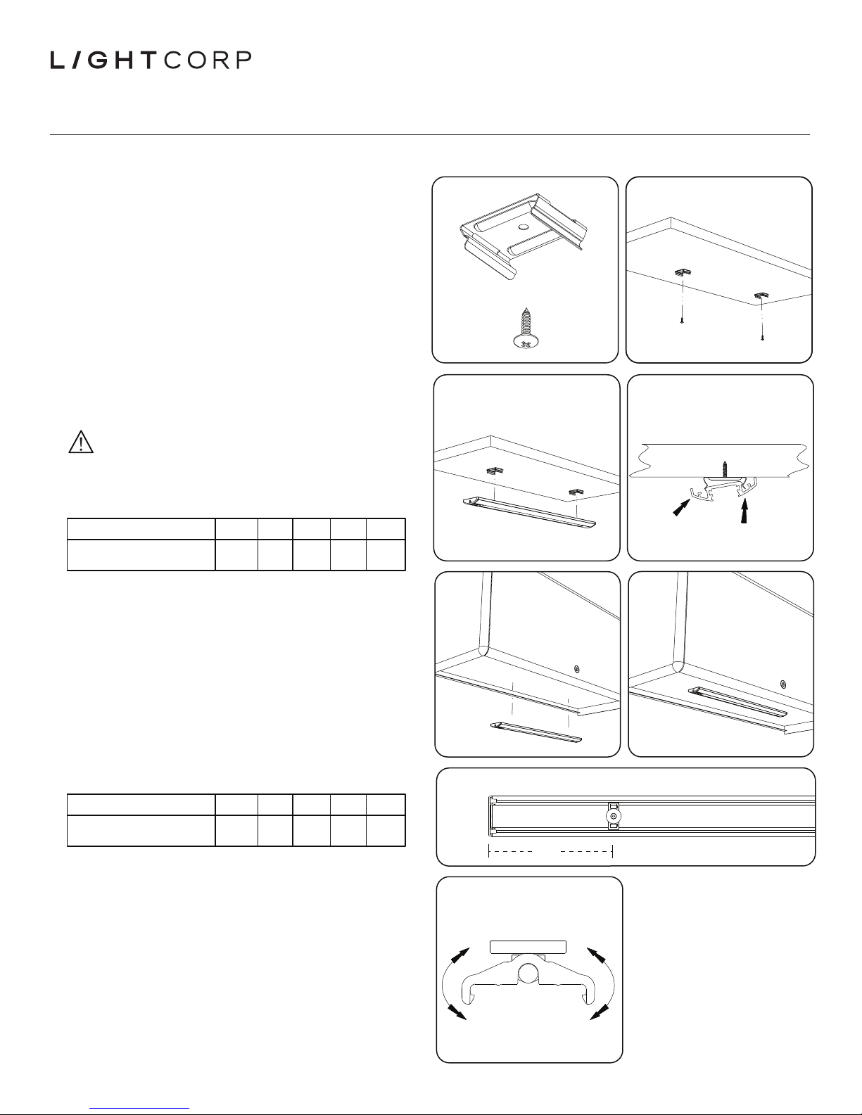
SCREW MOUNT
1. Kit includes two (2) bracket clips, two (2) screws (Fig. 1).
2. Screw bracket clip to shelf in desired location (approximately 12”
spacing centered under the shelf), ensuring that both clips are
oriented in the same direction (Fig. 2).
3. Raise xture to clip, aligning the channel on the back of xture
with clip and snap in place (Fig. 3 and Fig. 4).
4. Plug DC cord to either end of xture and route to power supply.
5. If equipped with an occupancy sensor, connect the third screw
bracket clip in-line with the two already installed, and
approximately 2” from the end of the xture. Connect the sensor to
xture and snap into place (Fig. 12).
6. Place power supply on any horizontal surface, allowing the plug to
be inserted into 120V AC, 60Hz, grounded outlet (Fig. 11).
STANDARD MAGNETIC MOUNT
Caution: Magnetic eld present in magnet mount xture.
1. Magnetic clips attach by clamping to the back surface of the
xture housing, for direct mounting to metal shelving.
2. For all xtures: use 1 magnetic clip per end located at the distance
specied for the given xture length (Fig. 7) in the table below:
FIXTURE FAMILY
Approximate clip distance
“X” from end of xture
3. Locate xture to the desired position on metal shelf (Fig. 5) and set
in place (Fig. 6).
4. Plug DC cord to either end of xture and route to power supply.
5. If equipped with an occupancy sensor, connect the standard
magnetic clip to the OS body and install (Fig. 12).
6. Place power supply on any horizontal surface, allowing the plug to
be inserted into 120V AC, 60Hz, grounded outlet (Fig. 11).
17”1”24”3”31”3”44”6”58”
9”
Fig. 1 Fig. 2
Fig. 3 Fig. 4
Fig. 5 Fig. 6
MAGNETIC ANGLE MOUNT
1. Magnetic angle clips attach by clamping to the back surface of the
xture housing for direct mounting to metal shelving.
2. For all xtures: use 1 magnetic angle clip per end located at the
distance specied for the given xture length (Fig. 7) in the table below:
FIXTURE FAMILY
Approximate clip distance
“X” from end of xture
3. Place one side of the clip against the xture housing and press the
opposite side down until it snaps into place. Adjust clip positions
to the recommended position shown above, by sliding into place.
4. Locate xture to the desired position on metal shelf (Fig. 5) and set
in place (Fig. 6).
5. Adjust light output angle to desired direction by rotating the xture (Fig.
8). For best results, push on the edge of the xture to change angle.
6. If clip doesn’t hold position, remove xture and tighten with a T10
driver. To remove, pry off one edge gently with a at head screw driver.
7. Plug DC cord to either end of xture and route to power supply.
8. If equipped with an occupancy sensor, connect the standard
magnetic clip to the OS body and install using exible cord
provided per the instructions on the reverse side.
CONTINUES ON BACK
17”1”24”3”31”3”44”6”58”
Fig. 7
9”
“X”
Fig. 8
12371.000.000 Rev M
REED PREMIER
MOUNTING INSTRUCTIONS
MAGNETIC ANGLE MOUNT (CONT’D)
9. Place power supply on any horizontal surface, allowing the plug
to be inserted into 120V AC, 60Hz, grounded outlet (Fig. 11).
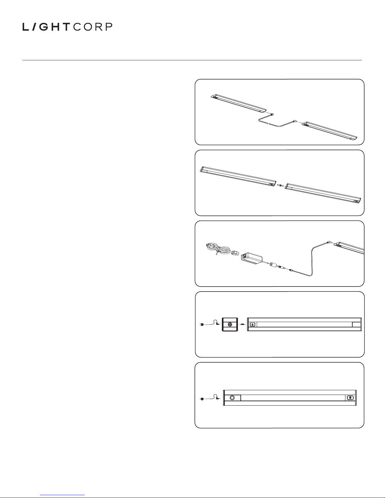
CONNECTING MULTIPLE FIXTURES
1. Route interconnect cord from one end of a xture to the end of
an adjacent xture (Figs. 9, 10). The maximum distance between
the interconnected xtures is determined by the length of the DC
cord provided, excluding the connectors.
2. Place power supply on any horizontal surface, allowing the plug
to be inserted into 120V AC, 60Hz, grounded outlet (Fig. 11).
3. Route the low power DC cord from power supply to either end of
one of the xtures.
NOTE: Route cords as to not kink or pinch, which may cause damage to
the cord. When connecting more than one xture, total wattage of
xtures must not exceed power supply rating, see components for
wattage rating. Cannot interconnect Reed Classic and Reed Premier.
REED OCCUPANCY SENSOR
Connection sequence: Power--> Sensor--> Connector--> Fixture
The optional Reed Integral Passive Infrared (PIR) occupancy sensor
automatically turns the xture off after 30 minutes of no detection.
Coverage: 360 degree lens view, 90 degree outward detection angle,
coverage of 36” diameter at 18” distance: 15 (i.e. Coverage
Diameter = 2 x Distance).
NOTE: Reed OS must be installed in-line between power supply and
xture (Fig. 12). Only one occupancy sensor is required per
interconnect line.
Fig. 9
Fig. 10
Fig. 11
REED INTEGRATED OCCUPANCY SENSOR
Connection sequence: Power--> Fixture (Occ sensor input)
The Reed Integral Passive Infrared (PIR) occupancy sensor
automatically turns the xture off after 30 minutes of no detection.
Coverage: 360 degree lens view, 90 degree outward detection angle,
coverage of 36” diameter at 18” distance: 15 (i.e. Coverage
Diameter = 2 x Distance).
NOTE: Reed OS must have power supplied to the occupancy sensor side
of the xture to properly operate (Fig. 13).
DIMMING
Touch and hold your nger on the touch pad. The xture will
brighten and then dim. Release the touch pad when preferred level
of brightness is obtained. Each time the xture is turned on it will
return to the level of brightness that was set by the user. To reset
the brightness to a different light level simply touch and hold the
touch pad. This will need to be performed on each xture.
RECOMMENDED CORD CONNECTOR
Hubbell Brand Nylon Cord Connector: SHC1022CR UL/CSA Listed,
HUB Size: 1/2”, Diameter Range: .25” - .38”
Note: This equipment has been tested and found to comply with the limits for a Class B digital device, pursuant to Part 15 of the FCC Rules. These limits are designed to provide reasonable protection
against harmful interference in a residential installation. This equipment generates, uses and can radiate radio frequency energy and, if not installed and used in accordance with the instructions, may
cause harmful interference to radio communications. However, there is no guarantee that interference will not occur in a particular installation. If this equipment does cause harmful interference to radio
or television reception, which can be determined by turning the equipment off and on, the user is encouraged to try to correct the interference by one or more of the following measures: Reorient or
relocate the receiving antenna, Increase the separation between the equipment and receiver, Connect the equipment into an output on a circuit different from that to which the receiver is connected, or
consult the dealer or an experienced radio/TV technician for help.
Fig. 12
Fig. 13
 Loading...