

Page 1

Last Rev. AV20180329
ORPHEUS
Collinear optical parametric amplifier of white light continuum
User’s Manual
UAB MGF Šviesos Konversija
Address: Keramikų 2B, LT-10233 Vilnius, Lithuania
Tel: +370 5 2491830
E-mail: [email protected]
www.lightcon.com
Page 2

Page 3

ORPHEUS User’s Manual
PREFACE
This manual contains user information for the non-collinear optical parametric amplifier ORPHEUS.
Please read this manual first before attempting to connect and/or operate ORPHEUS. Special
attention should be paid to the “Safety precautions” chapter, which describes the safety measures that
should be taken while using the device. Always use the instrument only for its intended purpose and as
described in the manual. Failing to do so may void the instruments warranty and compromise user’s safety.
This manual is intended to give the user thorough description of the operation of ORPHEUS, guidance
on daily usage of the device and troubleshooting advice in case of problems. The manual assumes that the
ORPHEUS has been installed by a qualified service engineer. The user is strongly advised not to attempt to
perform a new installation or re-installation of ORPHEUS by following this manual.
Information in this manual is believed to be accurate and reliable. All information in this document is
subject to change without notice. In no event will Light Conversion be liable for any direct or indirect
damages resulting from any defects in this documentation. Always consult Light Conversion Support Team
or your service engineer, if you have doubts about any instructions written in the manual before acting.
Thank you for using Light Conversion products.
The latest WinTOPAS software version
Download the latest WinTOPAS software version from Light Conversion website www.lightcon.com:
Go to “Support” → “OPA Software Update” for the download link. No login required.
Page 4

ORPHEUS User’s Manual
Page 5

ORPHEUS User’s Manual
TABLE OF CONTENTS
PREFACE ...................................................................................................................................................... 3
TABLE OF CONTENTS .................................................................................................................................. 5
List of Figures ...................................................................................................................................... 7
List of Tables ....................................................................................................................................... 7
SAFETY SIGNAL WORDS AND SIGNS ........................................................................................................... 8
1. SAFETY PRECAUTIONS ........................................................................................................................ 9
1.1 Optical Safety ......................................................................................................................... 9
1.2 Electrical Safety .................................................................................................................... 10
1.3 Warning and Information Labels .......................................................................................... 10
2. ELECTRICAL AND PHYSICAL SPECIFICATIONS ................................................................................... 12
2.1 Dimensions ........................................................................................................................... 12
2.2 Description of Input and Output Ports ................................................................................. 13
3. PUMP REQUIREMENTS ..................................................................................................................... 14
4. POSITIONING AND CONNECTING ORPHEUS .................................................................................... 15
4.1 System Layout on Optical Table ........................................................................................... 15
4.2 Fixing ORPHEUS on the Optical Table .................................................................................. 15
4.3 Beam Routing Units .............................................................................................................. 17
4.4 Connecting ORPHEUS ........................................................................................................... 17
4.5 Input Beam Shutter .............................................................................................................. 19
4.6 Interlock ............................................................................................................................... 20
5. DESCRIPTION OF OPERATION .......................................................................................................... 21
5.1 Overview .............................................................................................................................. 21
5.2 Pump Beam Delivery and Splitting ....................................................................................... 23
5.3 White Light Continuum Generator ....................................................................................... 23
5.4 Generation of the Second Harmonic of Pump ..................................................................... 23
5.5 First Amplification Stage ...................................................................................................... 24
5.5.1 The First Pass .................................................................................................................... 24
5.5.2 The Second Pass ............................................................................................................... 25
5.6 Second Amplification Stage .................................................................................................. 26
5.7 Output polarization .............................................................................................................. 27
5.8 Wavelength Separators ........................................................................................................ 27
5.9 Computer Controllable Motorized Stages............................................................................ 28
5.10 Computer Control of ORPHEUS ............................................................................................ 29
6. DAILY OPERATION ............................................................................................................................ 30
6.1 Setting the Wavelength ........................................................................................................ 30
6.2 Optimizing the Output ......................................................................................................... 30
7. OPTIMIZATION OF ORPHEUS PERFORMANCE ................................................................................. 31
7.1 Checking Pump Laser Parameters ........................................................................................ 31
7.2 Resetting Motor Positions .................................................................................................... 32
7.3 Input Beam Alignment ......................................................................................................... 32
7.4 Damage of Sapphire Substrate in White Light Generation Path .......................................... 33
7.5 Adjusting the Pump Intensity for White Light Generation .................................................. 34
7.6 Adjusting the Pump Intensity for the First Amplification Stage ........................................... 35
7.7 Applying Offsets for the Calibration Curve .......................................................................... 35
8. MAINTENANCE ................................................................................................................................. 37
8.1 General Maintenance ........................................................................................................... 37
8.2 Handling of Nonlinear Crystals ............................................................................................. 37
9. TROUBLESHOOTING GUIDE .............................................................................................................. 38
9.1 White Light Generation Does Not Occur/Is Instable ............................................................ 38
9.2 Low Parametric Output or No Output at All ........................................................................ 38
Page 6

ORPHEUS User’s Manual
9.3 Low Second Harmonic Generation Efficiency ...................................................................... 38
10. DISPOSAL ...................................................................................................................................... 39
10.1 Dismantling the System ....................................................................................................... 39
10.2 Disposal ................................................................................................................................ 39
Page 7

ORPHEUS User’s Manual
List of Figures
Figure 1. Location of the labels on the ORPHEUS body ................................................................................... 10
Figure 2. ORPHEUS housing dimensions and positions of input and output ports (mm) ................................ 12
Figure 3. Location of input and output ports on the ORPHEUS body .............................................................. 13
Figure 4. Recommended layout of ORPHEUS with an external Signal pulse compressor and pump laser ..... 15
Figure 5. Location of the three balls on which the device rests ...................................................................... 16
Figure 6. Positioning the feet of ORPHEUS on the optical table (SI system) ................................................... 16
Figure 7. Positioning the feet of ORPHEUS on the optical table (Imperial system) ......................................... 16
Figure 8. Location of the adjustment screws on the beam routing unit.......................................................... 17
Figure 9. Connectors of ORPHEUS.................................................................................................................... 18
Figure 10. The main USB control board of ORPHEUS ...................................................................................... 18
Figure 11. ORPHEUS extension plates (A or B) and shutter connector (C) ...................................................... 18
Figure 12. Shutter external view from input side and principle of operation ................................................. 19
Figure 13. Interlock defeat procedure ............................................................................................................. 20
Figure 14. Layout of the ORPHEUS subunits .................................................................................................... 21
Figure 15. Optical layout of ORPHEUS ............................................................................................................. 22
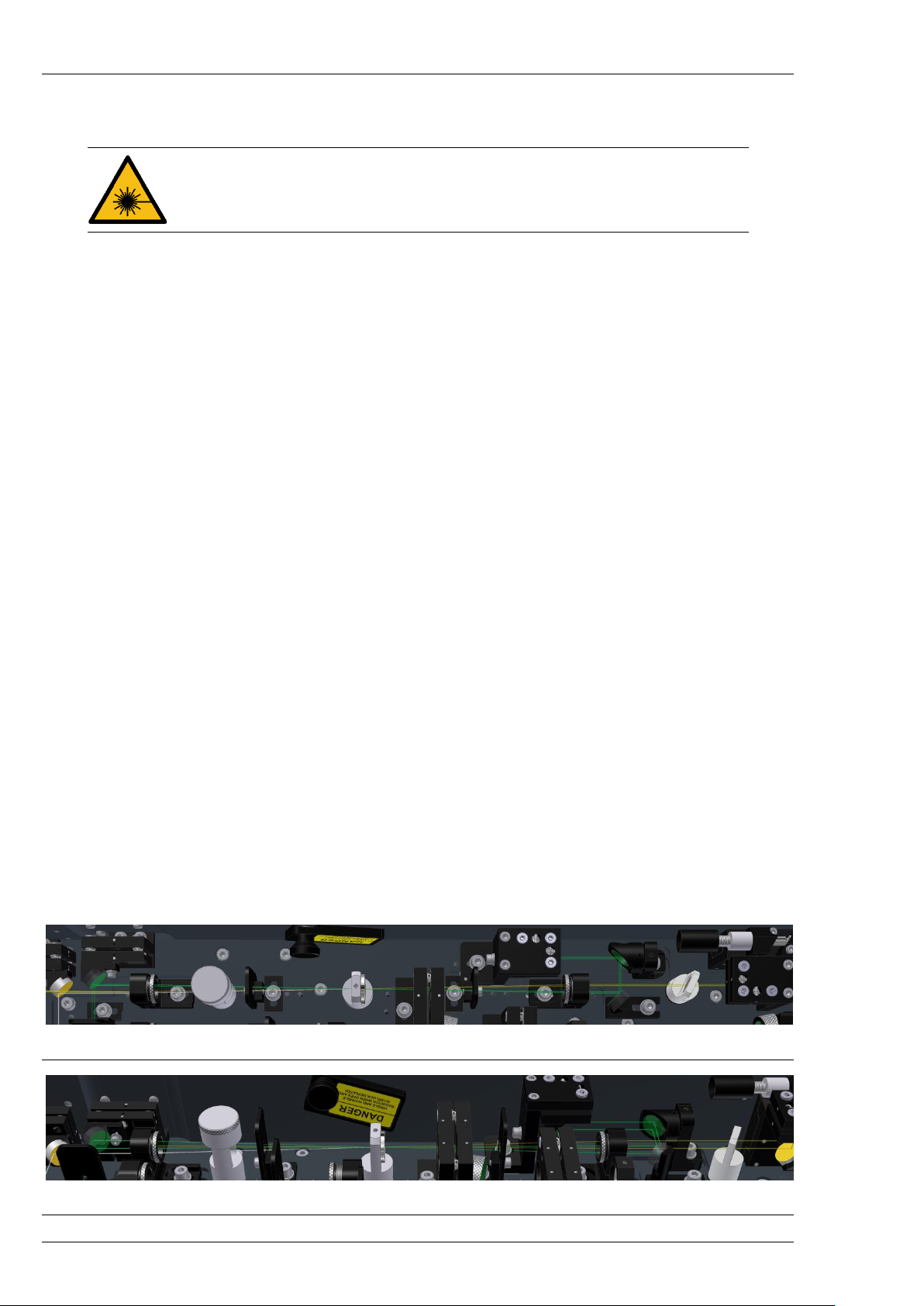
Figure 16. View of the first amplification stage from above ............................................................................ 24
Figure 17. View of the first amplification stage from the side ......................................................................... 24
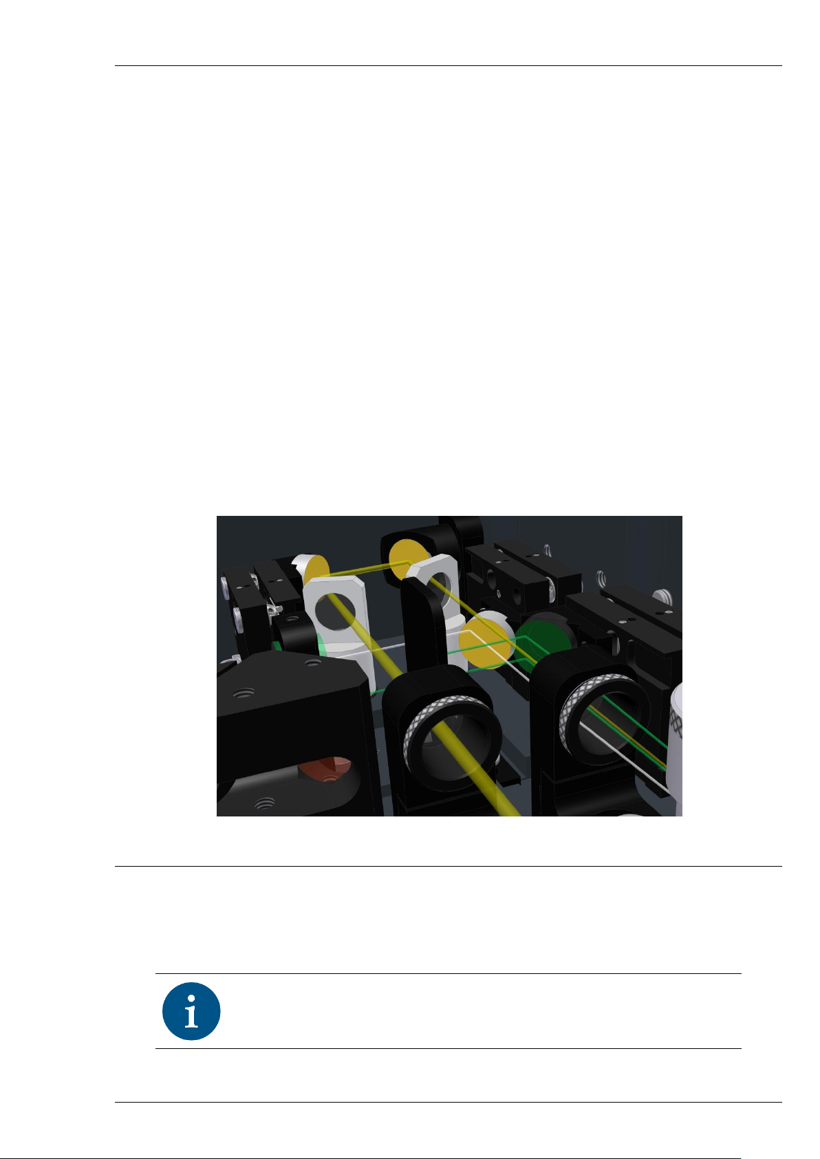
Figure 18. A closer look at the amplified seed beam exiting the first amplification stage after the second
pass. Yellow is the amplified beam, White – WLC, Green – pump .................................................................. 25
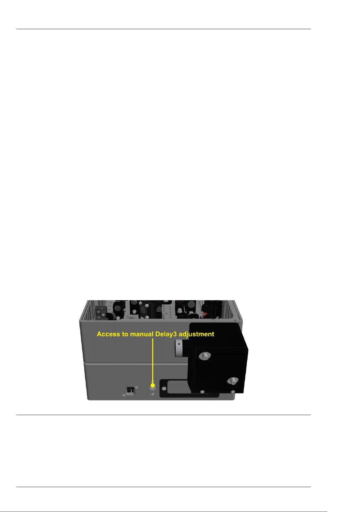
Figure 19. Location of the manual Delay 3 adjustment protective screw ....................................................... 26
Figure 20. Wavelength separator (WS) with and without metal cover ........................................................... 27
Figure 21. Location and names of the motorized stages inside ORPHEUS ...................................................... 28
Figure 22. Apertures inside ORPHEUS and placement of beam alignment targets during input beam
alignment. ........................................................................................................................................................ 33
Figure 23. Illustration showing a key inserted into the axial adjustment hole in the WLG adapter. .............. 34
Figure 24. No white light generation (a) and very low intensity of white light (b) are indications that there is
too little energy in the pulse, or the beam is focused improperly onto the crystal ........................................ 34
Figure 25. Low (a), medium (b) and high (b) intensity of white light generated in sapphire substrate by 1030
nm radiation ..................................................................................................................................................... 35
List of Tables
Table 1. Safety signal words and safety signs used in this manual .................................................................... 8
Table 2. Location and description of ORPHEUS labels ..................................................................................... 11
Table 3. Electrical and utility requirements ..................................................................................................... 12
Table 4. Physical specifications ........................................................................................................................ 12
Table 5. Description of ORPHEUS input/output ports ..................................................................................... 13
Table 6. ORPHEUS output polarizations ........................................................................................................... 27
Table 7. List of wavelength separators ............................................................................................................ 28
Table 8. Names and descriptions of the motorized stages inside ORPHEUS ................................................... 28
Page 8
ORPHEUS User’s Manual
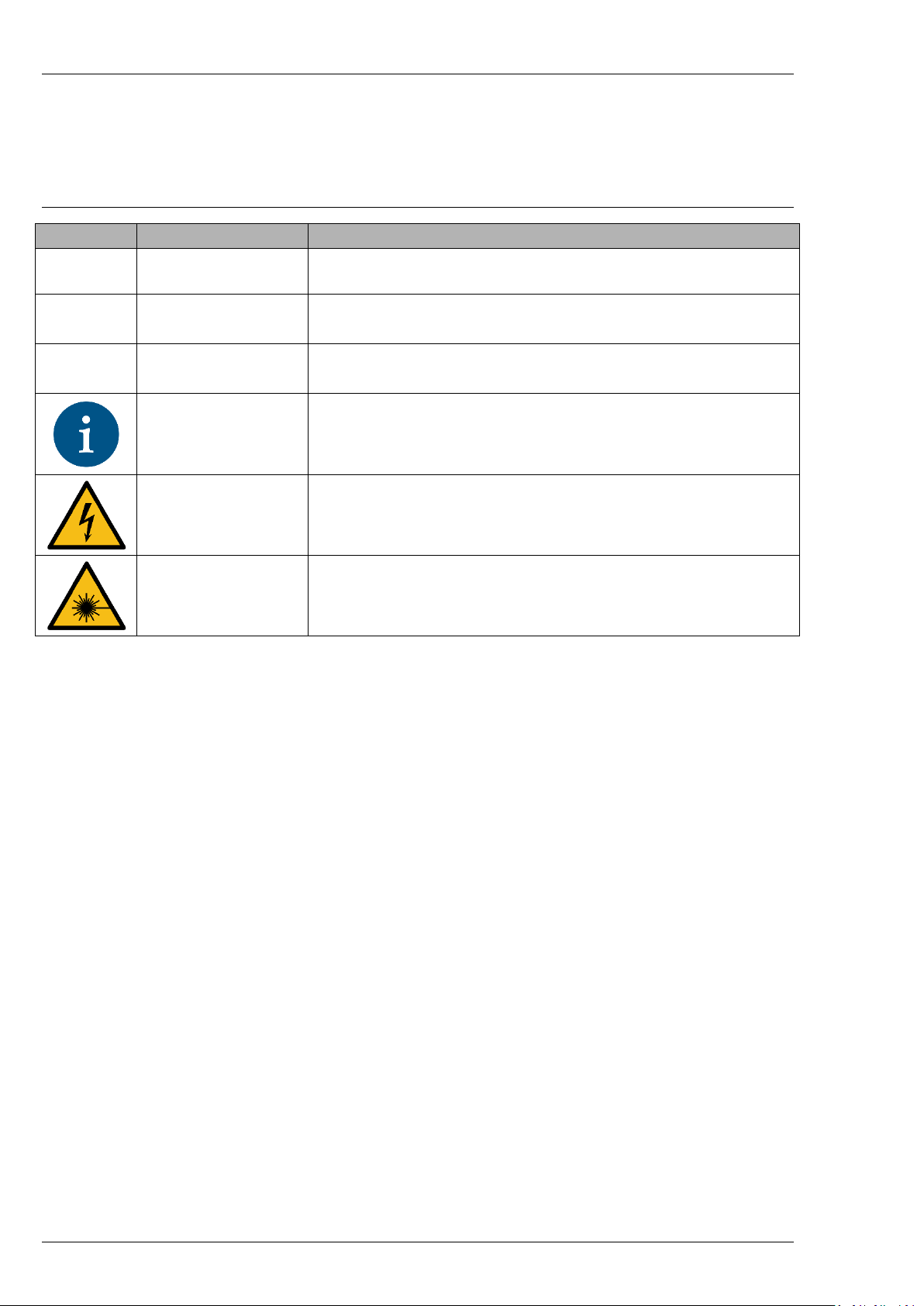
SAFETY SIGNAL WORDS AND SIGNS
The following safety signal words and safety signs are used throughout this manual:
Table 1. Safety signal words and safety signs used in this manual
Safety sign
Signal word
Description
DANGER
Indicates a hazardous situation that, if not avoided, will result in
death or serious injury.
WARNING
Indicates a hazardous situation that, if not avoided, could result in
death or serious injury.
CAUTION
Indicates a hazardous situation that, if not avoided, could result in
minor or moderate injury.
NOTICE
Indicates information considered important, but not hazard-related
(e.g. relating to property damage).
Indicates danger of electrical hazard to personal safety.
Indicates danger of exposure to hazardous laser radiation.
Page 9

ORPHEUS User’s Manual
1. SAFETY PRECAUTIONS
This section should be carefully reviewed prior to operating the ORPHEUS optical parametric
amplifier (OPA). Safety precautions contained herein and throughout the manual must be carefully
followed to ensure that all personnel who operate the laser and the OPA are protected from accidental
exposure to laser radiation and high voltage.
WARNING
ORPHEUS, when coupled with an appropriate pump laser,
comprises a Class 4 laser product. Avoid eye or skin exposure
to direct or scattered radiation. It may cause skin injuries,
eye damage with possible blindness, and could also
constitute a fire hazard.
ORPHEUS, when coupled with an appropriate pump laser, comprises a Class 4 laser product that
poses safety hazards if not used properly. Produced direct or scattered radiation can cause permanent eye
damage and possible blindness, skin injuries. Beams can be powerful enough to burn skin, clothes, or ignite
fire and can also damage light sensitive optical equipment such as video cameras, photodiodes, etc. It is
imperative that users learn all safety information, which is provided in the pump laser’s manuals.
1.1 Optical Safety
Maximum accessible radiation level from the ORPHEUS. The used and emitted power/pulse energy
by ORPHEUS may vary upon the type and model of pump laser used. The average input power may be
20 W, with pulse duration ranging from 100 to 300 fs. Emitted radiation can be over 20 W, 2 mJ and 10300 fs pulse width. The wavelengths emitted by/present in ORPHEUS are: 1030 nm, 515 nm, 620-3000 nm.
Additional frequency mixers extend the tunable range to 210 nm to 20 µm. Be very careful when aligning
and working with ORPHEUS.
WARNING
Avoid viewing the beam and specular reflections. Always
wear protective eyewear when aligning and operating the
ORPHEUS. Ensure your protective glasses cover all
wavelengths emitted by the laser system.
User is advised to follow the precautions below:
1. Always wear protective eyewear. Choose protective eyewear appropriate to wavelength and
intensity of the radiation, conditions of use, and visual function required. Remember that the
ORPHEUS output wavelength can be automatically and continuously tuned in broad wavelength
range.
2. Never look directly into the laser beam or scattered laser light from any reflective surface.
3. Avoid wearing watches, jewelry and other objects that may reflect or scatter the laser beam.
4. Set up the laser system so that laser beam paths are located well below eye level. Keep the
beams enclosed where possible.
5. Use energy absorbing targets and shields for beam blocking and preventing unnecessary
reflections or scatter.
6. Avoid blocking the laser beam or its reflection with any part of your body.
Page 10
ORPHEUS User’s Manual
7. Limit access to the laser system to qualified personnel only, who have received appropriate
safety laser training and are aware of dangers involved.
8. Use the laser system in a closed room. Laser light remains collimated over long distances and
therefore presents a potential hazard if not confined.
9. Do not work with ORPHEUS cover opened unless necessary. Intense light beams, their specular
and scattered reflections can be emitted from various parts of ORPHEUS when the cover is
opened.
10. Always keep the ORPHEUS powered for the safety beam shutter to operate correctly.
11. Post warning signs near the laser operation area.
1.2 Electrical Safety
1. Disconnect the power supply when working on any electrical equipment when it is not
necessary for the equipment to be operating.
2. Do not connect or disconnect any cables with the power supply connected to the mains
electricity.
3. Never work on electrical equipment unless there is another person nearby who is familiar with
the operation and hazards of the equipment, and who is competent to administer first aid.
4. The equipment must only be connected to a mains electricity with protective earth to avoid risk
of electrical shock.
WARNING
To avoid the risk of electrical shock, this equipment must
only be connected only to a mains electricity with protective
earth.
1.3 Warning and Information Labels
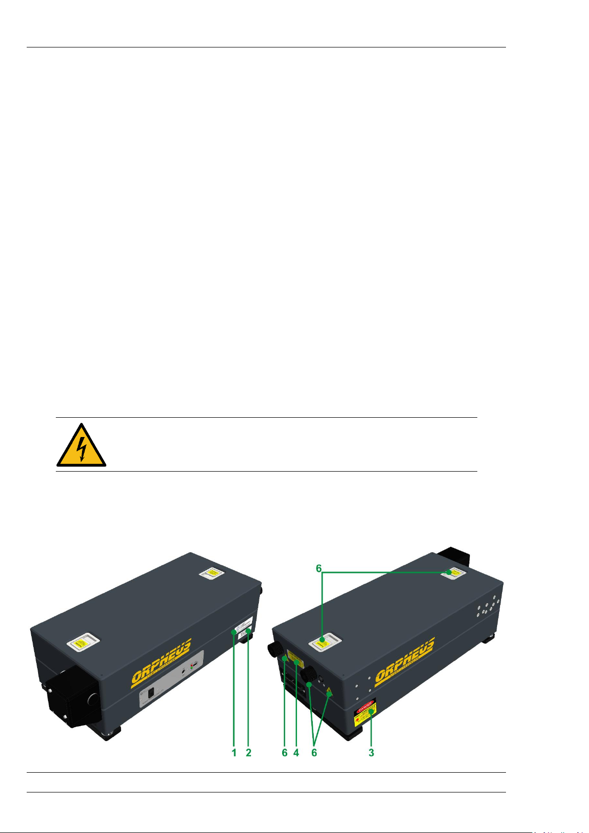
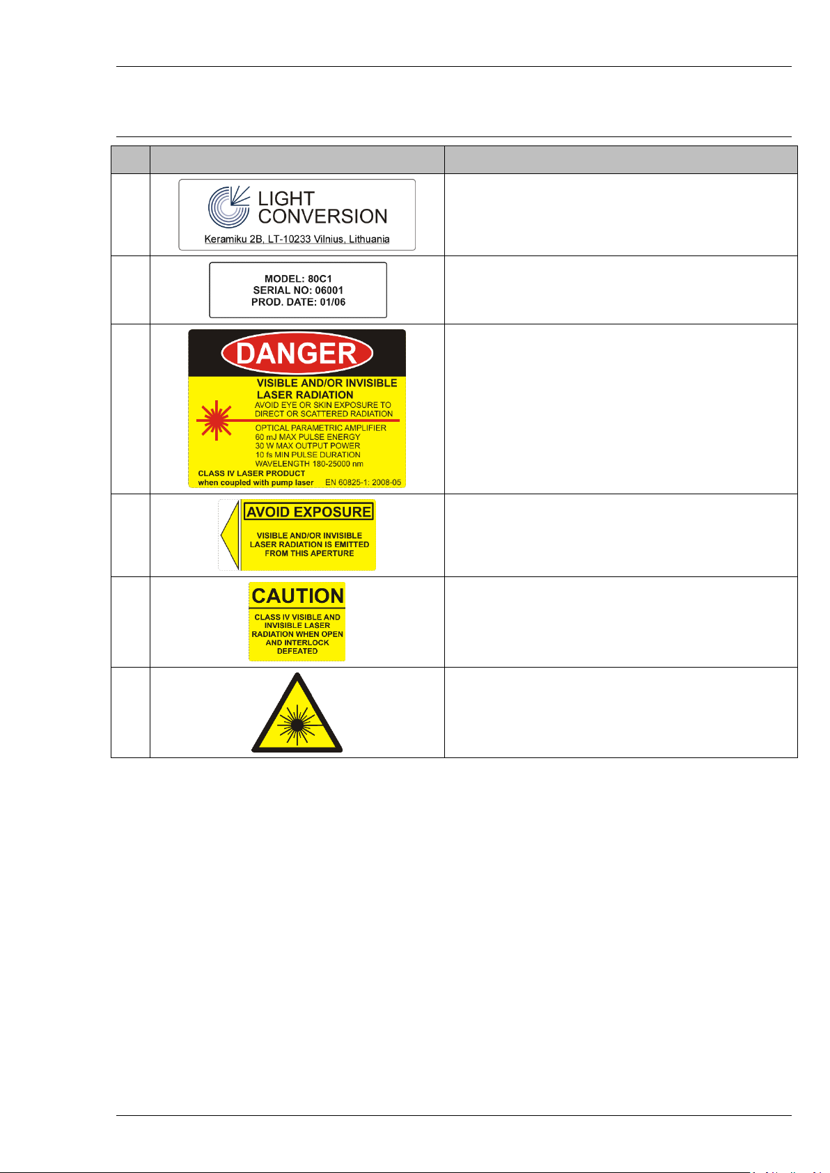
Description of ORPHEUS labels is presented in Figure 1 and Table 2.
Figure 1. Location of the labels on the ORPHEUS body
Page 11
ORPHEUS User’s Manual
Table 2. Location and description of ORPHEUS labels
No.
Label
Location and description
1
Manufacturer identification label is located on the
side of the ORPHEUS housing.
2
Device identification label is located on the side of
the ORPHEUS base below Manufacturer label.
3
Warning logotype is located on the side of the
ORPHEUS.
4
Aperture label is located next to the output aperture
of the ORPHEUS and points to it.
5
Label for defeatably interlocked housing is located
on the removable parts of the protective housing.
6
Laser radiation warning logo is located at every input
and output port of the housing.
Page 12
ORPHEUS User’s Manual
2. ELECTRICAL AND PHYSICAL SPECIFICATIONS
For indoor use only!
ORPHEUS is powered by external power supply provided by the manufacturer. Contact “Light
Conversion” support team before using a power supply from other manufacturers.
Table 3. Electrical and utility requirements
Power requirements (external power supply)
Voltage: 100–240 VAC
Frequency: 50/60 Hz
Max. current: 1.6 A
Power requirements (control board)
Voltage: 24 VDC
Max. current: 5 A
Altitude
Up to 2500 m
Operating temperature
15-40 °C
Relative humidity
10-70 % (non-condensing)
Table 4. Physical specifications
Length
590 mm
Width
230 mm
Height
163 mm
Weight
16 kg
Input/output port height
125 mm
Optical beam path length*
2.3 m
* From the input to the output port.
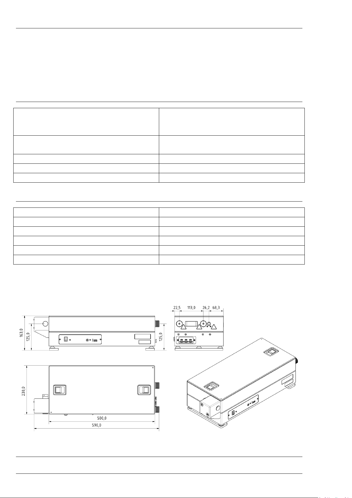
2.1 Dimensions
* Wavelength separator not pictured
Figure 2. ORPHEUS housing dimensions and pos itions of input and output ports (mm)
Page 13
ORPHEUS User’s Manual
2.2 Description of Input and Output Ports
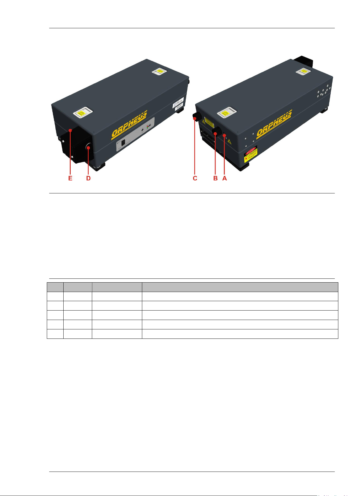
Figure 3. Location of input and output ports on the ORPHEUS body
Figure 3 show the layout of ORPHEUS input and output ports. Parametric radiation is emitted from
the main output port A. Depending on the system configuration, some of the input/output ports may not
be used, but there may still be some radiation emitted from those apertures. They should be blocked
accordingly. Full description of input and output ports is presented in Table 5.
There are also many smaller holes on ORPHEUS body, which are used during alignment of the device.
They are not specially identified; however, it is possible that some radiation may leak through these
apertures. Therefore, make sure that every alignment aperture is closed during normal operation.
Table 5. Description of ORPHEUS input/output ports
No.
In/Out
Wavelength
Description
A
Output
620-2600 nm
Main output port of the ORPHEUS
B
Output
515 nm
Residual second harmonic of pump from the power amplification stage
C
Output
1030 nm
Residual fundamental pump
D
Input
1030 nm
Pump laser input into ORPHEUS
E
Input
1030 nm
Pump laser input into ORPHEUS
Page 14

ORPHEUS User’s Manual
3. PUMP REQUIREMENTS
Good performance of ORPHEUS requires high pump quality in terms of both time and space
coherence. This means that ideal pump is diffraction-limited beam and transform-limited, high contrast
pulse. To some extent, performance of ORPHEUS is an indicator of quality of the pump laser radiation.
In femtosecond systems that use nowadays-standard chirped pulse amplification technique (CPA),
there are specific possible causes of distorted beam or pulse. Some of them are discussed below.
Spatial beam quality. Non-uniformity of the beam reduces the energy conversion rate. Presence of
hot spots in the beam may cause small-scale self-focusing that in turn leads to phase modulation. In the
nonlinear crystals, hot spots can also produce parametric superfluorescence or white light generation.
Increasing the average power in such cases could lead to damage of the crystal or other optical
components.
Spatial/temporal beam distortion. In contrast to long pulse lasers, astigmatism introduced by
improperly aligned lenses of beam expanders/reducers lead to distortion of temporal profile of the pulse
across the beam. This makes it impossible to overlap pump and signal pulses over entire beam aperture in
ORPHEUS.
Tilted pulses. This phenomenon manifests itself in similar way as that discussed above. However, it
originates from improper pulse compressor alignment. Tilted pulses are produced when the angular
dispersion is not completely cancelled. The problem with this kind of distortion is that it can be easily
overlooked using standard diagnostics equipment such as autocorrelator.
Underseeded regenerative amplifiers. The seed pulses for regenerative amplifier can be too week
due to low oscillator power, poor mode matching or improper Pockel’s cell timing. This results in rather
high energy content in the background. Background can be undetectable either by oscilloscope or by
autocorrelator. Simple test for background is measurement of build-up time of unseeded and seeded
regenerative amplifier. In last case the build-up time should be shorter at least by 15-20%.
Page 15
ORPHEUS User’s Manual
4. POSITIONING AND CONNECTING ORPHEUS
4.1 System Layout on Optical Table
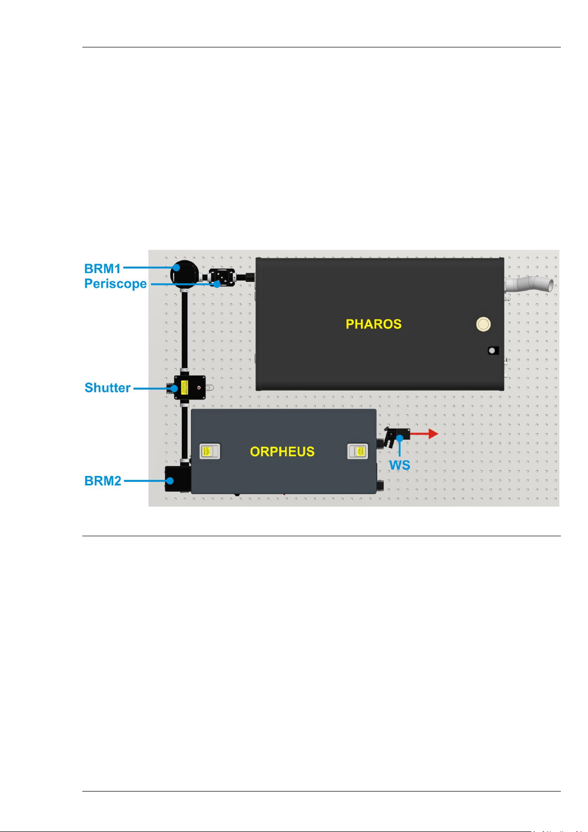
Figure 4 shows the recommended optical layout of ORPHEUS and pump laser. It is recommended to
position ORPHEUS along the side of optical table, about 5-20 cm from the table edge. Such a positioning
allows convenient access while aligning the device.
It is strongly recommended to fix all the system on the same optical table and as close as possible to
each other. Fixing the housings on a junction of the optical tables or letting the beam propagate several
meters until it enters ORPHEUS might increase the sensitivity of the system and/or lower the performance
especially in terms of long time scale instabilities.
Figure 4. Recommended layout of ORPHEUS with an external Signal pulse compressor
and pump laser
The beam from the amplifier is lifted to the input beam height level using a periscope. Depending on
the system layout, the periscope may direct the beam straight forward or at a 90 degree angle. Mirrors
BRM1 and BRM2 direct the beam to the ORPHEUS. The output beams exit the housing at the same height
as the input beam.
4.2 Fixing ORPHEUS on the Optical Table
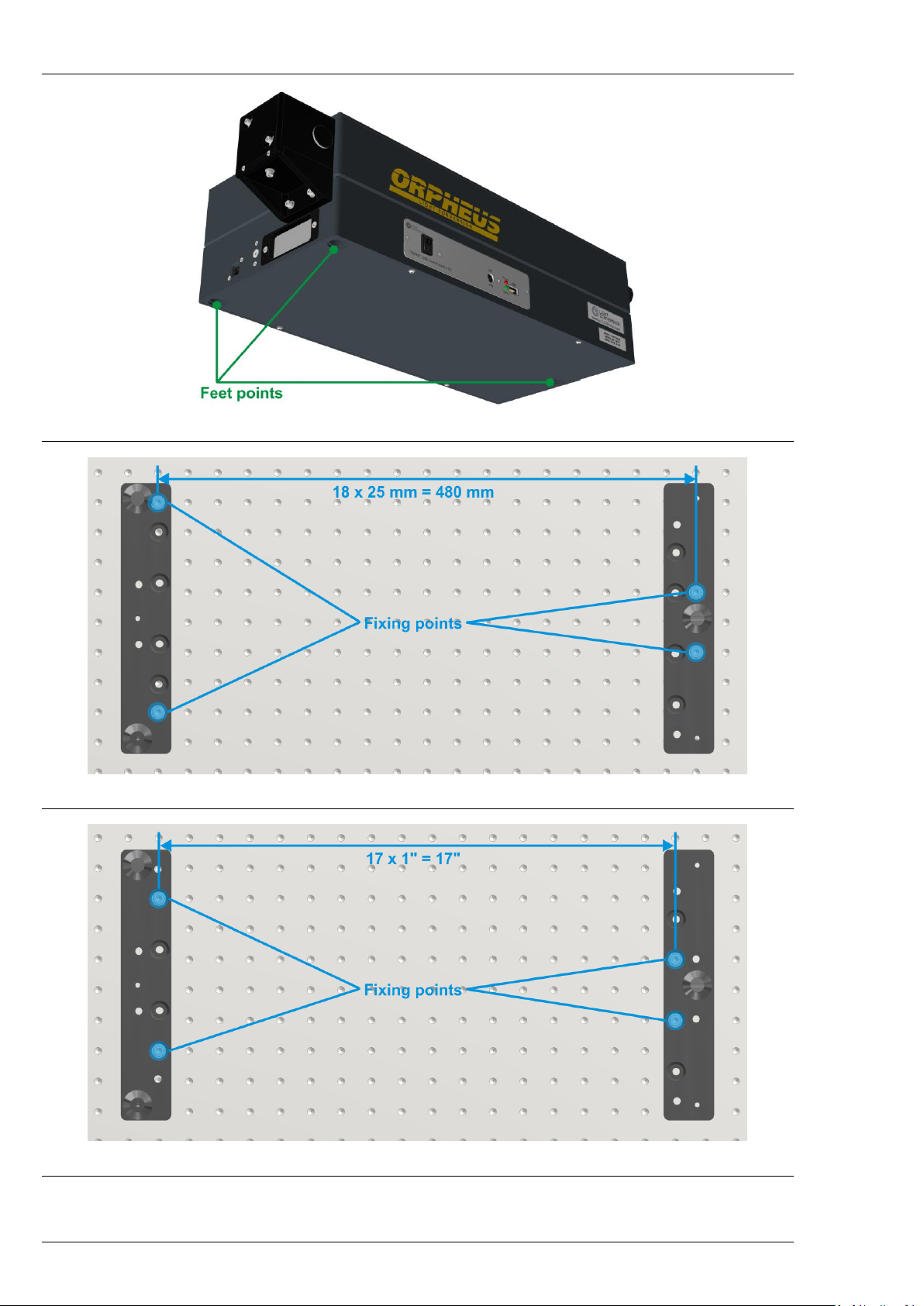
ORPHEUS housing is fixed onto the optical table using special feet. The device freely rests on these
feet via three balls located on the ORPHEUS body. The feet are assembled into pads prepared for the width
and length of the ORPHEUS. They are fitted to the height of the pump beam and are not height adjustable.
The pads have 8 mounting holes each. Only two of them should be used for fixing to the optical
table. Figure 6 shows correct positioning of the feet on an optical table with 25 mm hole spacing. Figure 7
shows the correct positioning of the feet on an optical table with 1 inch hole spacing. Notice that in this
case, different mounting holes should be used.
Page 16
ORPHEUS User’s Manual
Figure 5. Location of the three balls on which the device rests
Figure 6. Positioning the feet of ORPHEUS on t he optical table (SI system)
Figure 7. Positioning the feet of ORPHEUS on t he optical table (Imperial system)
Page 17
ORPHEUS User’s Manual
Do not operate the system if either ORPHEUS or the pump laser is not fixed to the optical table. This
could lead to dangerous misalignment of ORPHEUS and damage of internal components.
4.3 Beam Routing Units
Depending on the model of the pump laser and system layout, it may be necessary to use periscopes,
beam splitters (BS) and/or beam routing mirrors (BRM) to deliver the pump beam into ORPHEUS. Optical
components of these items are put in metal enclosures designed for safety and stability. These enclosures
are prepared for specific beam heights but are flexible in terms of system layout.
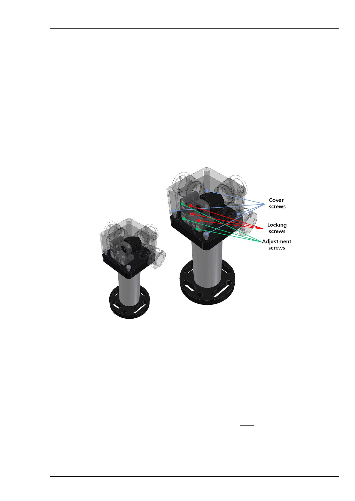
Tuning the angle of the mirrors is done by micrometer screws accessible with a 2 mm hex key,
location of the screws is shown in Figure 8. It is recommended to use only vertical and horizontal screws for
alignment (not diagonal). Depending on the model of the units, the position can be locked by tightening the
locking screws.
Figure 8. Location of the adjustment screws on the beam routing unit
The periscope consists of two mirrors and only the top mirror is coarsely adjustable. This mirror
should be only adjusted once during the installation to keep the beam parallel to the optical table.
All enclosed beam routing units, periscope, and shutter are interconnected with hollow tubes to fully
enclose the beam path. This is necessary to ensure user safety and stability of the OPA output.
4.4 Connecting ORPHEUS
ORPHEUS needs to be connected to the power supply and to a computer to operate. Additionally, if
the system is supplied with water cooled beam dumps, water supply must be connected to the device. If
water is not available, beam dumps must be replaced with air-cooled alternatives.
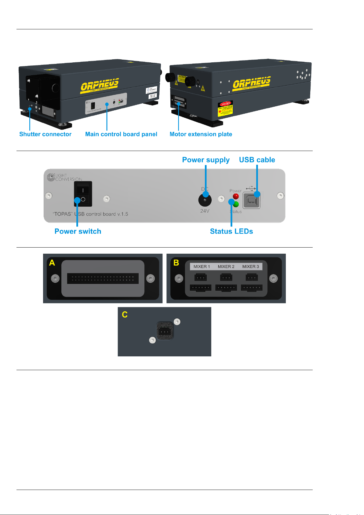
ORPHEUS has three connection panels (Figure 9). The panel of the main circuit board for the power
supply and USB connection (Figure 10) is located on the side of ORPHEUS body. Shutter connector is
located on the front side. The connectors (extension plate) for external devices are located on the back
Page 18
ORPHEUS User’s Manual
side, below the output ports. In some configurations the main circuit board connections might be in front
of the ORPHEUS housing, below the attached beam routing mirror.
Figure 9. Connectors of ORPHEUS
Figure 10. The main USB control board of ORPHEUS
Figure 11. ORPHEUS extension plates (A or B) and shutter connector (C)
The sequence of connecting the ORPHEUS should be as follows:
1. Water cooling to the water-cooled beam blocks, if applicable.
2. External devices (Mixers, LYRA, etc.) to the extension plate.
3. Shutter cable to the dedicated shutter connector.
4. USB cable.
5. Power supply cable.
6. Install WinTOPAS from your USB flash disk.
7. Turn on the USB control board.
8. Install the control board driver as described in WinTOPAS user’s manual.
Page 19
ORPHEUS User’s Manual
NOTICE
Always make sure the USB control board is powered off
before connecting the extension cables.
Use only power supplies from Light Conversion. Power supply from Light Conversion is suitable to
both 110 V and 220 V outlets. Make sure that the main circuit board’s switch is in “OFF” position before
connecting the power supply.
WARNING
Always check that the supply and its cables are in proper
condition and do not show any damage to any part of the
insulation, before connecting.
It is recommended to install the WinTOPAS software before connecting ORPHEUS to computer.
Follow the instructions in the software start guide. Connect ORPHEUS to computer using supplied USB
cable.
Power LED (Red) should be always on and Status LED (Green) should blink with intervals of ~1 second
during normal operation of the USB control board. The software needs to be configured for a device,
hardware settings file must be linked in the software. Consult the WinTOPAS user’s manual on software
configuration.
A single computer can control up to 5 of the USB control boards. A USB-hub can be used if the
computer does not have enough USB ports. Light Conversion does not guarantee proper operation of
ORPHEUS with non-branded USB-hubs.
4.5 Input Beam Shutter
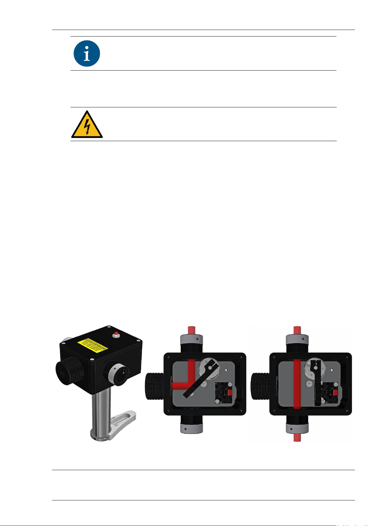
ORPHEUS is equipped with a stand-alone external shutter (see Figure 12a). Its primary purpose is to
enhance user safety while working with ORPHEUS. External shutter also safely dissipates the heat of the
input radiation.
a) b) c)
Figure 12. Shutter ex ternal view from input side and principle of operation
Principle of operation relies on HR1030 mirror placed on a rotary solenoid. When the solenoid is not
powered (turned off), the mirror is directing the input beam sideward into the air-cooled or water-cooled
Page 20
ORPHEUS User’s Manual
beam dump (Figure 12b). When power is supplied to the solenoid, the mirror is displaced out of the beam
path and the beam is passed through (Figure 12c). The red LED lights up when power is supplied to the
shutter. The WinTOPAS3 software displays the current state of the shutter and provides the control for
opening and closing it.
The software displays the current state of the shutter and provides the control for opening and
closing it (see WinTOPAS start guide).
WARNING
Always keep the control board powered for the shutter to
operate correctly and for the WinTOPAS to display correct
shutter status.
4.6 Interlock
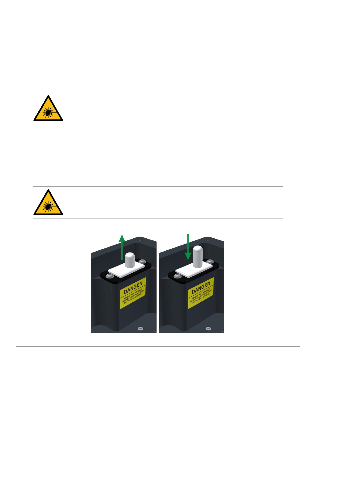
ORPHEUS is equipped with an interlock mechanism. It is impossible to open the shutter when the
interlock is active. The interlock is activated when an electrical circuit is broken, which happens when
ORPHEUS cover is opened. This releases the button thus breaking the circuit.
CAUTION
Never work with ORPHEUS cover removed unless aligning
the device. Always pay close attention to safety precautions
detailed in this manual, documentation of the laser and
regulations in your laboratory.
To defeat the interlock, pull the button upwards.
Figure 13. Interlock defeat procedure
Page 21
ORPHEUS User’s Manual
5. DESCRIPTION OF OPERATION
5.1 Overview
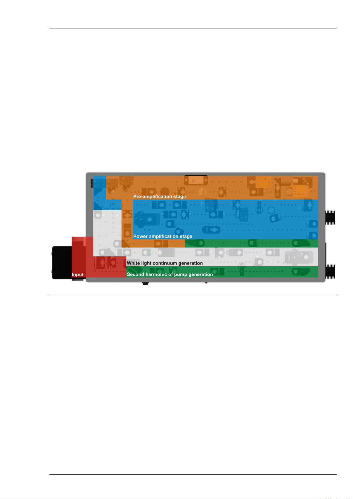
ORPHEUS is a two-stage optical parametric amplifier of the white light continuum. The device
employs computer-controlled translation and rotation stages for several key optical components, providing
fast automated wavelength tuning. The basic configuration consists of the several subunits:
1. White light continuum generator.
2. Second harmonic of the pump beam generator.
3. First amplification stage (a non-collinear two pass pre-amplifier).
4. Second amplification stage (a collinear power amplifier).
These subunits are arranged in a single compact housing. Layout of the subunits is shown in Figure 14
and the full optical layout of ORPHEUS is presented in Figure 15.
Figure 14. Layout of the ORPHEUS subunits
ORPHEUS can accept a variety of input pulse energies, repetition rates, beam sizes, etc. However,
during installation, it is set and optimized for fixed pump parameters, which should not change by more
than ±10 % for ORPHEUS to operate. A decrease of pump pulse intensity might lead to lower efficiency of
ORPHEUS, narrower spectral widths or even no output if white light generation cannot be obtained. An
increase of pump pulse intensity poses a risk of damaging several optical components and non-linear
crystals. If it is needed to operate ORPHEUS at different pump pulse parameters – replacement of several
optical components and realignment should be performed to match new pump conditions, and it is usually
done by a trained engineer. This manual does not cover the option of operating ORPHEUS with variable
pump pulse parameters.
The beams present inside ORPHEUS are dangerous not only to the human eye or skin, they can also
heat and cause damage to the internal mechanical and optical components if the device is not aligned
properly. Reflection shields and protective covers are used inside ORPHEUS to catch most of the unwanted
reflections and residual radiation before it reaches the sensitive components. It is highly recommended to
block the pump beam (close the shutter) whenever the system is not in use.
Page 22
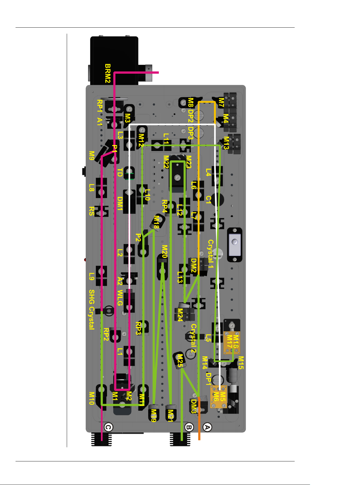
ORPHEUS User’s Manual
A
C
Crystal
DM
DP
Figure 15. Optical layout of ORPHEUS
– iris aperture
– compensator
– amplification crystal
– dichroic mirror
– delay plate
L
M
P
RP
RS
– lens
– mirror
– polarizer
– half-wave plate
– reflection shield
SHG
Crystal
TD
WLG
– second harmonic generation crystal – temporal dispersion medium
– white light generation substrate
Page 23

ORPHEUS User’s Manual
5.2 Pump Beam Delivery and Splitting
Pump beam from the laser is directed into ORPHEUS using external mirror BRM1 and mirror BRM2,
which is attached to OPA housing. The beam then passes an iris aperture A1 and a polarization rotator RP1
(λ/2 plate). A1 should always be fully open, unless aligning the device at very low pump intensities only.
Beam height from the base plate of ORPHEUS at the input is 25 mm. A polarizer P1 reflects most of the
pump beam energy for second harmonic generation and transmits 0.2–1.5 µJ for white light continuum
generation (depends on configuration).
5.3 White Light Continuum Generator
After passing the polarizer P1, pump beam polarization is rotated to vertical by RP2. The beam then
travels to the retro reflector which consists of two mirrors M1-M2, placed on a computer-controlled
translation stage (“Delay 1” in the software). Computer controlled adjustment of the optical path length of
pump beam ensures the temporal overlap of white light and pump pulses in the first amplification stage.
The lens L1 is set to focus the beam into the WLG – white light continuum generation substrate. The
white light should be stable and single filament. The best way to check the shape of the WLC is to place a
business card right after the iris A2. If the WLC is not visible, its shape is asymmetric or has an interference
pattern - proceed to the troubleshooting section of this manual.
Iris aperture A2 blocks the outer rings of the WLC. Under normal operation it is closed to about 1-2
mm diameter. The beam passes through the L2 lens. Dichroic mirror DM1 reflects the residual pump beam
downwards and transmits the white light continuum. The reflected residual pump is blocked inside DM1
mount.
Lens L3 is used to ensure proper diameter of the WLC at the amplification crystal Crystal 1. The pulsewidth of the continuum pulse at lens L2 is roughly the same as the initial pump pulse (~300 fs). The TD
element disperses the white light in time due to group velocity dispersion – different wavelengths travel
through the substrate at different velocities. After the TD the longest wavelength (1040 nm) arrives earlier
than the shortest one (620 nm). The resulting pulse-width of the chirped white light after the TD element is
roughly 12-20 ps, depending on the thickness and substrate of the material of TD element used. This white
light continuum will be overlapped at the nonlinear crystal with a ~200 fs long pump pulse. By tuning the
“Delay 1” translation stage a different spectral region of white light is overlapped temporally with the pump
pulse, which allows selective seeding of the amplification process.
5.4 Generation of the Second Harmonic of Pump
Major part of pump beam, which is reflected by the polarizer P1 and mirror M9, is used for
generation of the second harmonic of laser radiation. Lenses L8 and L9 constitute a down-collimating
telescope. At very low pump pulse energies (<20 μJ), the beam after the telescope is not collimated, rather
it is set to focus near the nonlinear crystal. The reduction factor and focusing condition is chosen depending
on the pump pulse parameters during the installation.
The second harmonic generation SHG Crystal is placed on a computer-controlled rotation stage
(“SHG Crystal” in the software). By changing the angle of the crystal, it is possible to some extent to
attenuate the power of the second harmonic radiation, and in turn – signal and idler radiation, however it
can also change the wavelength, pulse duration, beam size of the parametric radiation pulses. The crystal
Page 24
ORPHEUS User’s Manual
can also be rotated completely out of the beam path, giving access to the full first harmonic trough output
port C of the ORPHEUS.
CAUTION
Never block the pump or second harmonic of pump beam
with a paper card. The card will ignite; the fumes may
gather onto the optical components and cause permanent
damage. When necessary, use metal beam blockers only.
M10 mirror reflects only the second harmonic radiation and directs it toward mirror M11. The
residual fundamental radiation is then blocked at the output port, or input into further wavelength
extension device. Beam height of the second harmonic at M11 is 20 mm. The beam then passes through a
rotator of polarization RP3 and polarizer P2. The beam transmitted through the polarizer (a smaller
fraction) is used for the first amplification stage, the reflected beam – for the second amplification stage.
Splitting ratio depends on the system configuration
5.5 First Amplification Stage
The pre-amplifier is used to produce stable and sufficiently bright seed pulses for the second
amplification stage. It employs a two-pass configuration using a single nonlinear Crystal 1.
The beam path of the pump in the preamplifier:
• first pass: L4-Crystal 1-L5-M14-M15-M16/M17
• second pass: M16/M17-M15-M14-L5-Crystal 1-C1-L4
The beam path of the white light continuum:
• first pass: L4-Crystal 1-L5-DP1-M5
• second pass: M6-DP1-L5-Crystal 1-C1-L4
5.5.1 The First Pass
The pump beam and WLC arrive at the lens L4 separated horizontally by 4 mm. The height of both
beams is 20 mm from the baseplate. The beams then travel below the compensator crystal C1 and into
nonlinear Crystal 1. The lens L4 focuses both beams into the same spot at Crystal 1 at the height of
22.5 mm, where amplification occurs. The wavelength of the amplified pulse is selected by tuning the
position of “Delay 1” stage and angle of “Crystal 1” in the software. The pump beam and the amplified
pulse then travel to the L5 lens where they are again separated by 4 mm, but now the beam height is
25 mm.
Figure 16. View of the first amplification stage from above
Figure 17. View of the first amplification stage from the side
Page 25
ORPHEUS User’s Manual
Mirrors M14 and M15 then direct the pump beam into the retro reflector M16/M17, which
translates the beam downwards by 5 mm. The amplified WLC beam travels beside the M14 mirror through
the delay plate DP1 and into the M5/M6 retro reflecting periscope.
5.5.2 The Second Pass
Periscope M5/M6 is fixed on a manual translation stage which is used to coarsely overlap the second
pass pump and WLC beams in time at the Crystal 1. Fine tuning of the temporal overlap is done by rotating
the delay plate DP1 (“Delay 2” in the software).
After the M5/M6 periscope, the amplified white light travels through the DP1 for the second time
and arrives at the L5 lens 5 mm below the first pass WLC beam. The second pass pump beam arrives at L5
5 mm directly below the first pass pump.
Once again, the WLC and pump beams are focused into the Crystal 1 at the height of 22.5 mm – the
same spot as the first pass. After Crystal 1 both pulses travel above the first pass beams and this time they
travel through the C1 compensator crystal. This crystal is used to compensate the spatial drift of the
amplified WLC due to the rotation of nonlinear crystal Crystal 1. After C1 the beams arrive at L4, where
they are 5 mm above their first pass counterparts.
The residual pump beam then hits the mirror M13 and is blocked by the reflection shield. The
amplified WLC beam travels above the M4 mirror and onward to the power amplification stage. Figure 18
illustrates the beams exiting the pre-amplifier.
Figure 18. A closer look at the amplified seed beam exiting the first amplification stage
after the second pass. Yellow is the amplified beam, White – WLC, Green – pump
The pump intensity in Crystal 1 should be high enough for efficient amplification of white light
however it should be below the threshold of white light generation in the nonlinear crystal. This is because
the threshold for white light generation in BBO crystal is very close to the damage threshold. White light
generation in Crystal 1 could also be an indication of dust or damage on the surface of the crystal.
NOTICE
Never operate ORPHEUS if the pre-amplifier pump beam
generates white light inside Crystal 1. This can lead to
damage of the crystal.
Page 26
ORPHEUS User’s Manual
Correct pump intensity in Crystal 1 can be chosen rotating the half wave plate RP3. This should be
done during the device installation. Consult support team before performing any adjustments. An indicator
of sufficient pump intensity in the first amplification stage is super fluorescence originating from the
Crystal 1 crystal when the white light seed is blocked. You can check for SFL by placing a white card in front
of the M5/M6 periscope and setting 650 nm wavelength in the software. You may be able to see a part of a
red super-fluorescence ring (some of it is blocked by the M14 mirror). If the SFL is visible but the
amplification of the white light does not occur, it means that either the temporal or spatial overlap of the
pump beam and the WLC in the Crystal 1 is off. On the other hand, the SFL does not have to be visible for
amplification to occur.
5.6 Second Amplification Stage
The amplified portion of the white light continuum (seed) after exiting the first amplification stage
first travels through two delay plates DP2 and DP3. They are placed on a computer-controlled rotation
stage (“Delay 3” in the software) and are used to fine-tune the temporal overlap of seed and pump pulses
at the Crystal 2. Lenses L6 and L7 re-collimate the beam and adjust the diameter so that it matches the
diameter of the pump beam at Crystal 2. Dichroic mirror DM2 transmits the seed and reflects the pump
beam. After amplification at the nonlinear crystal, parametric radiation is separated from the pump beam
by mirror DM3 and is emitted from output port A of ORPHEUS.
The pump beam reflected by polarizer P2 and mirror M18 propagates to folding mirrors M19, M20
and M21. Beam height at these mirrors is 25 mm from the base plate. Half wave plate RP4 rotates the
polarization back to horizontal – needed for pumping nonlinear crystal Crystal 2. The beam then travels to a
retro reflector M22/M23, which is placed on a manual translation stage. It is only necessary to adjust the
position of this stage after alignment or replacement of some optical components has been performed.
Tuning the position of these mirrors is required to ensure proper temporal overlap of pump and seed
beams at the Crystal 2. To adjust this translation stage first remove the screw at the input side of ORPHEUS
(see Figure 19), then use a 3 mm hex key to turn the micrometer screw.
Figure 19. Location of the manual Delay 3 adjustment protective screw
The intensity of the second pump beam is adjusted by lenses L12 and L13. These lenses are chosen
during installation of the device for fixed pump pulse parameters. The second harmonic pulse then
propagates to beam steering mirrors M24 and DM3 and into the nonlinear Crystal 2. This crystal is also
mounted on a computer-controlled rotation stage (“Crystal 2” in the software). As in the first amplification
stage, pump intensity at Crystal 2 is not far from the damage threshold for the BBO crystal. This limit
Page 27
ORPHEUS User’s Manual
increasing the pump energy by more than ~10 % of the nominal value (pump energy at the time of
installation).
After amplification, the residual pump is separated from the amplified pulse at the dichroic mirror
DM3 and is directed towards output port B by mirror M25.
The beam path of the pump beam (515 nm) in the power amplifier:
• P2 – M18 – M19 – M20 – M21 – RP4 – M22 – M23 – L12 – L13 – M24 – DM2 – Crystal 2 – DM3 –
M25 – Output B
The beam path of the seed:
• M7 – M8 – DP2 – DP3 – L6 – L7 – DM2 – Crystal 2 – DM3 (transmitted) – Output A
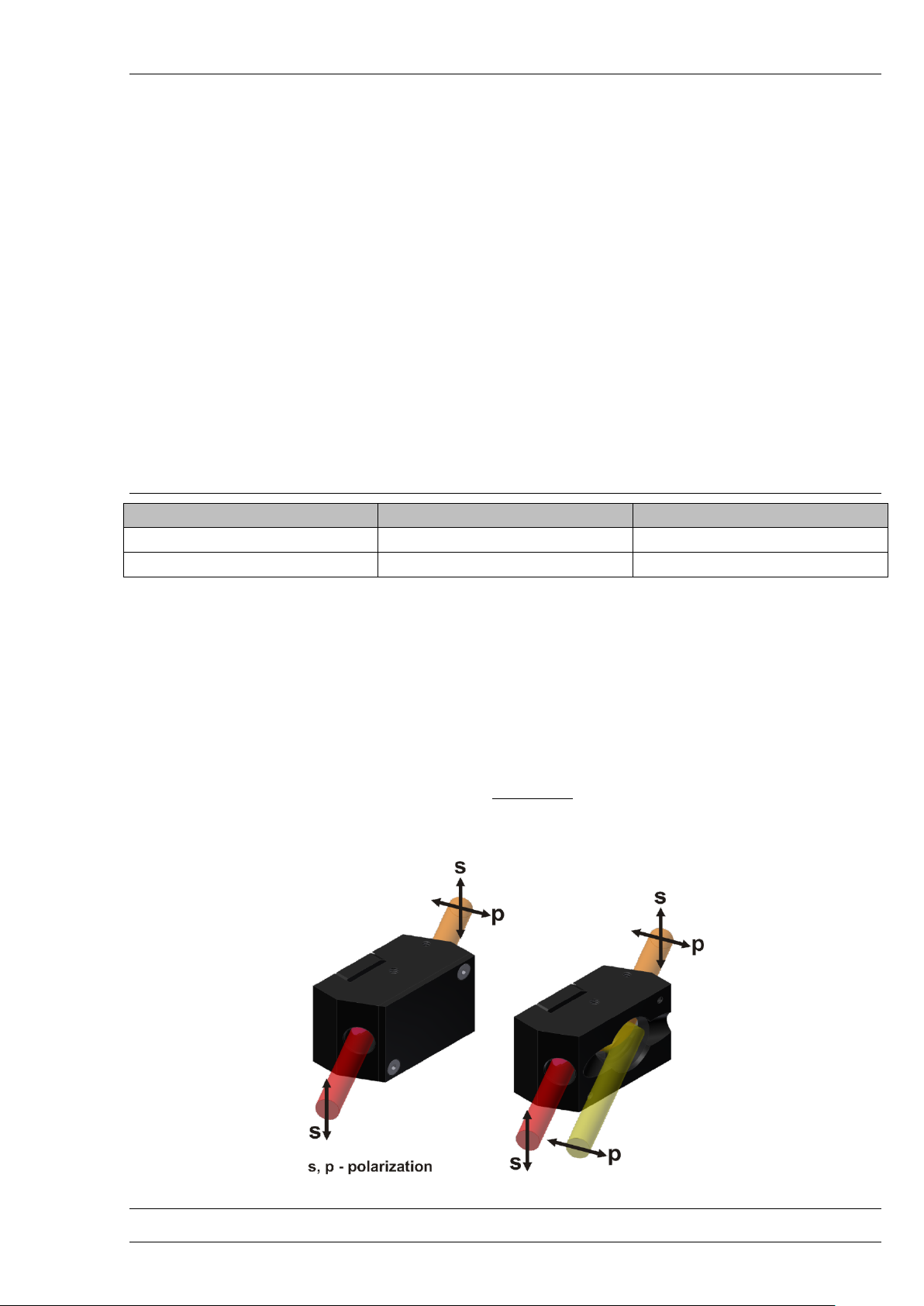
5.7 Output polarization
Below is a table with ORPHEUS tuning range and output polarizations.
Table 6. ORPHEUS output polarizations
Interaction
Output wavelength range
Polarization
Signal
620–1040 nm
Vertical
Idler
1030–2600 nm
Horizontal
5.8 Wavelength Separators
Duo to the collinear nature of amplification used in the power amplifier of ORPHEUS, Signal and Idler
waves both exit the housing at the same position and direction. If only one of those is required for your
application, the beams can be separated by using optional wavelength separators (WS). Each WS consists of
two dielectric mirrors with high reflectivity (HR) coatings for a specific wavelength region. Depending on
whether the Signal or Idler wave is reflected, the WS can be mounted in two orthogonal positions – the
beam is either translated sideways (horizontally) or downwards (vertically). The two mounting positions are
necessary because Signal and Idler waves are of orthogonal polarizations and the mirrors efficiently reflect
s polarization only. A list of available wavelength separators is presented in Table 7.
Figure 20. Wavelength separator (WS) with and without metal cover
Page 28
ORPHEUS User’s Manual
One of the beams is transmitted through the first mirror and then blocked by the metal cover. If
necessary – this cover can be removed. The beams then travel in the same direction, separated horizontally
or vertically by ~13 mm (Figure 20).
Table 7. List of wavelength separators
WS number
Range of reflected wavelengths
Interaction
Polarization
Mounting position
WSO-1
1970 – 2600
Idler
Horizontal
Downward
WSO-2
1550 – 1970
Idler
Horizontal
Downward
WSO-3
1385 – 1550
Idler
Horizontal
Downward
WSO-4
1030 – 1385
Idler
Horizontal
Downward
WSO-5
755 – 1030
Signal
Vertical
Sideward
WSO-6
600 – 765
Signal
Vertical
Sideward
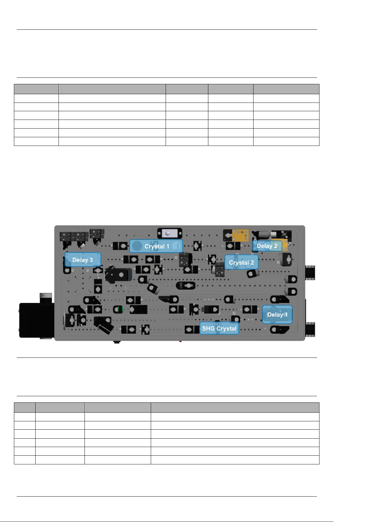
5.9 Computer Controllable Motorized Stages
There are 6 automated stages inside the OPA device that control the angle or position of several
optical components.
Additional wavelength extension modules will require extra motorized stages. They are described in
the manuals of those modules. Currently, up to 12 motors can be controlled by a single USB control board.
Figure 21. Location and names of the motorized stages inside ORPHEUS
The figure above shows the positions of the motorized stages, and the table below describes their
use in wavelength tuning.
Table 8. Names and descriptions of the m otorized stages inside ORPHEUS
No.
Name
Optical element
Description
1
Delay 1
M1+M2
Pre-amplifier wavelength tuning
2
Crystal 1
Crystal 1+C1
Pre-amplifier crystal phase matching angle
3
Delay 2
DP1
Pre-amplifier second pass temporal overlap
4
Delay 3
DP2+DP3
Power amplifier temporal overlap
5
Crystal 2
Crystal 2+C2
Power amplifier crystal phase matching angle
6
SHG Crystal
SHG Crystal
Second harmonic (515nm) crystal angle
Page 29

ORPHEUS User’s Manual
5.10 Computer Control of ORPHEUS
ORPHEUS is controlled through a USB interface of a computer and dedicated WinTopas4 software
package. WinTopas4 should be installed by a field service engineer during the set-up of the system. You can
find a last configuration backup in a USB memory stick, provided with the system user’s manual:
• 18000_Configuration.zip – device configuration files (where “17000” is a serial number of the
device). Download the latest version of WinTopas4 installer from “Light Conversion” website.
• WinTopas4-preconf(18000)-setup.exe (optional) – preconfigured installer, consisting of all system
devices configuration files and WinTopas4 software. No separate WinTopas4 installation is
required.
For more information, downloads, tutorial videos and instructions please visit WinTopas4 info page:
topas4info.lightcon.com
Control of the ORPHEUS can also be integrated into the user’s software. For more information please
visit Topas4 Public API help page:
topas4api.lightcon.com/current
If you experience problems with the software, please contact:
Page 30

ORPHEUS User’s Manual
6. DAILY OPERATION
The ORPHEUS device should always be powered on – every time it is switched off the motors lose
their position by a few steps. In that case it may be necessary to reset their positions using the WinTOPAS
software, this operation is described in the troubleshooting section. Every time the power to ORPHEUS is
switched off/on, the USB cable may need to be re-connected to the computer.
The pump laser should be turned on by following the guidelines in the user’s manual for the laser.
Typical warm-up time for the system from a cold start should be about 20-30 minutes. It is recommended
to let the system warm up before opening the main shutter of ORPHEUS.
Before operating ORPHEUS, always inspect that the laser is operating at the same parameters as
during installation of the device. Check that you are using the same repetition rate and laser power. Use of
the pulse picker feature to lower the repetition rate is acceptable. Never operate ORPHEUS with higher
than nominal input pulse energy, when OPA was aligned by trained service engineer. Too high pulse
energy may result in damage to the optical components.
6.1 Setting the Wavelength
1. Start the WinTOPAS application.
2. Select the device to be operated (only applicable if more than one OPA/NOPA is controlled by the
same computer).
3. Type in the wavelength of interest and press Enter.
4. Place an appropriate wavelength separator at the output of ORPHEUS to separate the Signal and
Idler beams.
5. Open the shutter by pressing the button in the software.
Please refer to the manual of WinTOPAS for more information on software operation and other ways
to control the output of ORPHEUS.
6.2 Optimizing the Output
To optimize the power, you should first try to optimize the angle of “SHG crystal” stage while
monitoring the output with a power meter. The angle of this crystal is very sensitive, and second harmonic
generation can be severely diminished even if the stage is off by only a few steps. Tuning is performed via
the “Motors” section in WinTOPAS. The next motors to check would be “Crystal 2” and “Delay 3”. Changing
the positions of these stages also influences the output wavelength, so it is recommended to check the
output with a spectrometer as well.
If you find it necessary to optimize one motor at every wavelength by a constant number of steps,
you can introduce an offset to the calibration curve. Follow the instructions of paragraph 7.7 in the
troubleshooting section.
If the OPA is producing insufficient parametric output, input beam alignment should be checked. It is
possible to gently push the BRM2 module in various directions while monitoring the output power – this
provides a non-destructive way to check if the input beam direction needs optimization. If you see that
doing so increases the output, you can adjust the fine screws of the BRM2 kinematic mount with a 2 mm
hex key to maximize the power.
Page 31

ORPHEUS User’s Manual
7. OPTIMIZATION OF ORPHEUS PERFORMANCE
7.1 Checking Pump Laser Parameters
The output performance of ORPHEUS is very sensitive to the input beam/pulse parameters. If the
output from ORPHEUS changes significantly – the parameters of the pump laser would be the first thing to
check.
The most important pump laser characteristics are the following:
1. Pump pulse energy.
2. Pump beam profile, diameter and collimation.
3. Pump pulse duration and compression.
4. Wavelength and spectral width.
5. Contrast ratio (pre- and post- pulses).
6. Stability of output parameters (pulse-to-pulse).
Pump pulse energy is supposed to be kept the same or at least ±10-15% from the energy that was
used during the installation. If the pump pulse energy will be significantly lower – there might be no output
from ORPHEUS or the output might be significantly lower, instable. If pulse energy is high – there is a risk of
damaging optical components of ORPHEUS and the crystals. Pulse energy might change because of the
following:
• Different pump current of laser diodes in laser.
• Changes of internal repetition rate of laser.
• Clipping of the beam on beam steering optics, damage of beam steering optics.
• Additional pump beam splitting or attenuation before ORPHEUS, etc.
• Degradation of the elements of amplifier or misalignment of cavity (lower output).
Pump pulse energy can be calculated from total power of pump laser and repetition rate. Please
check the installation documentation for pump pulse energy for ORPHEUS.
The profile of the beam should be at least visually inspected from time to time. Hot spots in the
beam profile, diffraction patterns because of clipping might create small scale non-linear effects or even
damage of the optical components inside ORPHEUS. The change of the diameter and/or collimation will
change the focusing conditions of the beams inside leading to lower/no output from the system.
Different pulse duration and compression affect the output of ORPHEUS similar as different pulse
energy. The compression/duration however does not change the energy of the pulse, but it changes the
peak intensity. Usual indicator of problems with pulse duration is white light generator of ORPHEUS: if
pulse duration is instable or higher than usual – WLC intensity will also be instable or it may even not be
possible to obtain white light generation. This appears in most of the cases because of CW presence in the
output from oscillator. Different pulse duration can originate from:
• Misalignment of compressor length – can be checked/adjusted from the remote control.
• CW spectral modulation of oscillator output – can be monitored with a spectrometer.
• Nanosecond operation if oscillator is off / not mode-locked / in CW regime / seed is blocked.
• Misalignment of stretcher / amplifier / compressor.
• Different wavelength and spectral width from the oscillator.
Page 32

ORPHEUS User’s Manual
If the oscillator is off/not mode-locked/CW – the amplifier might deliver the same output power at
slightly higher pump currents for laser diode bars. The output of unseeded regenerative amplifier is of
nanosecond pulse duration and the intensity is too low to pump ORPHEUS. In such a case it is not possible
to have white light generation in ORPHEUS, generation of the second harmonic is inefficient. The easiest
way to identify unseeded operation of the amplifier is monitoring the photodiode of regenerating amplifier
with the oscilloscope: the build-up trace is different from normal cavity-round-trip incremental signals of
photodiode in seeded operation (see user’s manual of amplifier for more details).
Wavelength and spectral width affect calibration of ORPHEUS. Phase matching angle of the crystals is
a function of pump wavelength. If the change is even within 1 nm range – the angle might no longer be
optimal. If the central wavelength of the pump cannot be recovered – the alignment of harmonic crystals
and offsets (or even recalibration) for the tuning curves of ORPHEUS might be necessary.
Pulse contrast ratio also affects the pulse energy of “real” pulse. Only the most intense pulse takes
part in amplification. Pre-pulses and post-pulses reduce the efficiency of harmonic generation and more
energy is needed for white light generation. The contrast ratio can be checked with fast photodiode and an
oscilloscope. Please refer to the manual of pump laser on optimization of pulse contrast.
7.2 Resetting Motor Positions
Reset of motor positions may be necessary after an electrical failure or software issues. There is no
feedback from the rotation/translation stage to control card to monitor the exact position. The feedback –
reset switch – is only at the very beginning of total moving range of the stage. Reset procedure of the
motor double checks the absolute position of stage with respect to reset switch: the software rotates the
motor until the stage hits a microswitch button and then moves the stage to position at which it was left
from the software.
This procedure is performed by pressing a “Reset all” button in the “Motors” section of WinTOPAS
software.
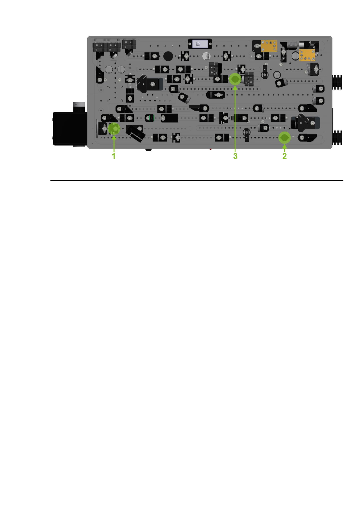
7.3 Input Beam Alignment
In case of pump laser alignment or a change in system layout, it may be necessary to re-introduce the
pump beam to ORPHEUS. This is performed by using alignment apertures (BT) inside ORPHEUS and special
beam alignment targets. The beam should travel through the center of these apertures. The positions
where to place the BTs when aligning the pump beam are shown in Figure 22. Consult Light Conversion
support team ([email protected]) first before performing any alignment.
Firstly, the beam should be centered on the iris A1 (marked by number 1 in the figure above) and on
the beam alignment target placed in the position marked by number 2. The correct procedure is to center
the beam on the iris by tuning the BRM1 mirror and then to center the beam on the target by tuning the
mirror BRM2. It may take several iterations to get the beam centered on both apertures.
NOTICE
Never use the full pump power to align the beam. Do not
close the A1 iris when ORPHEUS is operating at full
(nominal) power. This could result in damage of several
optical components in the beam path.
Page 33
ORPHEUS User’s Manual
Figure 22. Apertures inside ORPHEUS and placement of beam alignment targets during
input beam alignment.
Once the beam is centered on the first two apertures, proceed to place the BAT in the position
marked as number 3 in the illustration and align the BRM2 mirror to center the beam on this aperture.
When it is done, remove the BAT and start to increase the pump power. Final alignment should be
performed while monitoring the output power of ORPHEUS, attempting to achieve the installation value.
At the output of ORPHEUS Signal and Idler beams should be collinear. It is most convenient to check
that with an IR beam viewing card, which is sensitive to radiation near 1550nm wavelength. (For example,
Thorlabs VRC4 card, or Edmund Optics #55-292). If you set ORPHEUS to 770nm wavelength, you should see
three beams exiting ORPHEUS (515nm pump as green, 770nm Signal as red and ~1500nm Idler as yellow
spots would overlap on the card, when ORPHEUS is aligned properly)
7.4 Damage of Sapphire Substrate in White Light Generation Path
Depending on the intensity and repetition rate of pump used for white light generation, the
substrate itself can be damaged. Quite usual indicator of the damage is the scattering of white light on
surfaces of substrate: normally look like dust particle stuck to the surface of substrate right on the beam
position. The damage might occur on the first or second surface of substrate.
If it is not possible to generate white light at all having the same parameters from the pump laser –
that might also indicate the damage of the surface or bulk of substrate.
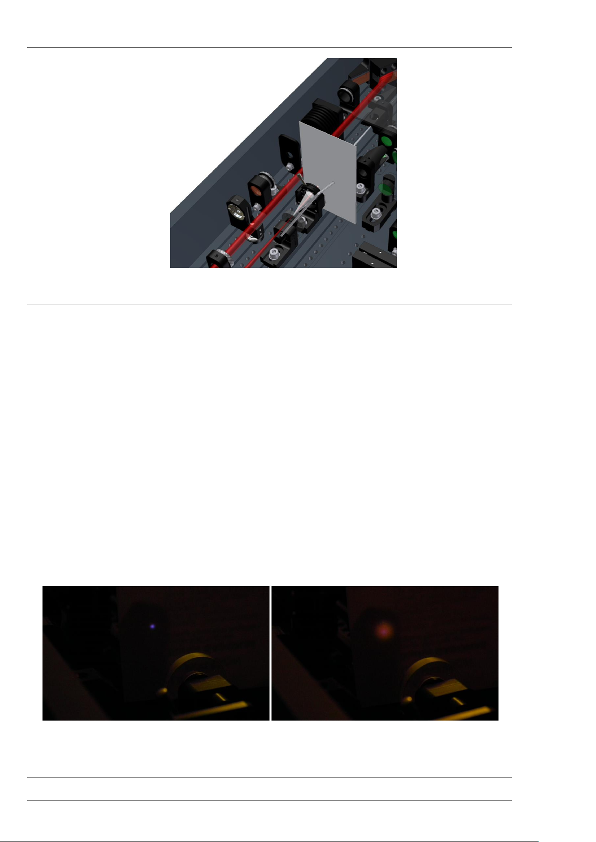
In both cases the damage spot can be avoided rotating the sapphire substrate around the axis. Please
note that sapphire substrate is glued on the pin which is fixed in the holder with a nylon tipped set screw.
Do not release this screw while rotating the sapphire! Axial shift of sapphire might affect the
stability/strength of white light signal as well as the focusing conditions of the beam into the nonlinear
crystal.
To rotate the sapphire substrate:
1. Block the Second Harmonic Generation beam path of ORPHEUS
2. Insert HEX 1.5-2mm key in the hole on the opposite end of pin of sapphire
3. Rotate the pin around the axis slightly
4. Check if there is no scattering on the surfaces of sapphire while generating white light
Page 34
ORPHEUS User’s Manual
Figure 23. Illustration showing a key inserted into the axial adjustment hole in the WLG
adapter.
If it is not possible to generate white light in fresh spot of substrate – proceed to the section
“Checking Pump Laser Parameters”. Probably the absence of white light is because of different pump
parameters.
7.5 Adjusting the Pump Intensity for White Light Generation
The intensity of pump for white light generation can be adjusted by rotating the half wave plate RP1:
1. Block the SHG beam path of ORPHEUS.
2. Set a business card after the A2 iris to monitor white light
3. Release the screw holding the RP1 λ/2 plate adapter.
4. Turn the adapter monitoring the WLC intensity, stability and shape.
5. Tighten the screw again. Make sure the WLC has not changed after tightening.
White light should be stable and single filament – there should be no interference patterns seen in
the beam profile (some rings can be seen around the central part – they can be ignored). If the intensity is
too high – white light might have “boiling” structure or interference fringes across the beam. If the intensity
is too low – white light might be instable, appearing/disappearing.
(a) (b)
Figure 24. No white light generation (a) and very low intensity of white light (b) are
indications that there is too little energy in the pulse, or the beam is focused improperly onto
the crystal
Page 35
ORPHEUS User’s Manual
(a) (b) (c)
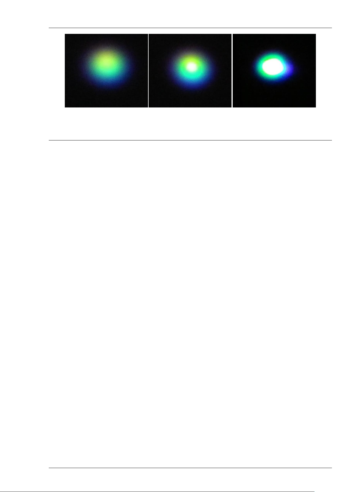
Figure 25. Low (a), medium (b) and high (b) intensity of white light generated in sapphire
substrate by 1030 nm radiat ion
Note that all the above illustrations are images taken at 100 kHz rep. rate. Images taken at lower rep.
rates, or beam profile viewed by eye may appear slightly different (a more reddish hue can be expected).
7.6 Adjusting the Pump Intensity for the First Amplification Stage
The intensity of pump for the pre-amplifier can be adjusted by rotating the half wave plate RP3:
Consult Support Team first before performing any adjustments!
1. Block the WLC beam.
2. Request 650 nm wavelength in the software.
3. Place a business card before the M5/M6 periscope.
4. Release the screw holding the adapter.
5. Turn the adapter while monitoring the intensity of SFL on the business card.
6. Tighten the screw and double check the SFL intensity.
The super-fluorescence should be viewed with goggles that block the green part of the visible
spectrum and transmit the red. The correct intensity of the pump is when the SFL is barely visible or not
visible at all. Be very careful when rotating the half wave plate – too high pump intensity could easily
damage the nonlinear crystal. Absence of SFL could also be an indication of inaccurate angle of the Crystal 1
crystal – the “Crystal 1” stage should be reset before increasing pump intensity.
7.7 Applying Offsets for the Calibration Curve
After minor alignment of ORPHEUS or small change in pump parameters the calibration curve can be
corrected by applying an offset for the motors involved. In most cases only the “Delay 1” motor should use
a calibration offset. If the offset is small enough – it can be also used for “Delay 2” and “Delay 3” motors.
However, the changes for those motors should first be compensated by adjusting the manual translation
stages of ORPHEUS. For “Delay 2” the “manual offset” is the M5/M6 periscope. For “Delay 3” – the
M22/M23 retro reflector. The position of these units is adjusted by a micrometer screw. For M5/M6 this
screw is accessible by hand when the cover is open. For M22/M23 the screw is adjusted with a 3 mm hex
key through the hole in the ORPHEUS body on the input side (see Figure 19).
An offset for “Crystal 1” or “Crystal 2” stages would most likely be necessary after nonlinear crystal
replacement.
Page 36

ORPHEUS User’s Manual
To apply an offset:
1. Reset motor positions.
2. Switch to “Advanced user level” in WinTOPAS application using the menu “Tools” → “Access
level”. The password for advanced user level is “1600”.
3. Set 680 nm as an output from the ORPHEUS.
4. “Calibration” → “Optical” → “OPA” → “SIG” and select the motor (for which you want to apply an
offset) on the left side of the window to gain access to the calibration curve.
5. For the same motor, select the motor control section on the right side of the window.
6. Adjust the position of the selected motor monitoring OPRHEUS output: spectrum and/or pulse
width.
7. Press “Set Offset”.
8. Repeat steps 4-6 for other motors you want to apply an offset.
The offsets for each motor are stored in calibration configuration. The settings of each calibration
point remain unchanged. The logic of setting the wavelength with and offset is the following:
1. Lookup for the motor position from the calibration curve.
2. Interpolate the position if in-between wavelength is entered.
3. Add/subtract each motor position by the offset.
If the offset is re-zeroed – the position of each motor will be the same as the original calibration
unless “Shift curve to make offset zero” was pressed after setting the offset. This function adds or subtracts
offset value from the current tuning curve and makes the offset permanent. Visit WinTopas4 info page for
more information.
Page 37

ORPHEUS User’s Manual
8. MAINTENANCE
8.1 General Maintenance
ORPHEUS does not have any consumable parts. The lifetime of the device is mostly limited by the
environment it is operated or stored in. Dust and humidity are the key factors affecting the long-term
performance. Additionally, high repetition rate or extreme average power systems may suffer from
degradation of the non-linear crystals. Re-positioning the nonlinear crystals, or even replacing them may be
necessary after a few months or even weeks, depending on input parameters and how often the device is
used.
Cleaning:
• Exterior of the ORPHEUS housing can be cleaned with soft cloth moistened with ethanol. Do not
use Acetone! While cleaning, take care that the dust does not contaminate the external or
internal optics!
• Never clean inside of the housing due to risk of optics and crystal contamination.
NOTICE
Never touch the optics with bare hands. Clean surfaces
immediately, if touched.
• Clean optics only when necessary. When cleaning, use acetone (methanol, ethyl acetate) of
>99.5% purity.
• Do not attempt to clean surfaces of gold/silver/aluminum mirrors due to risk of damage.
8.2 Handling of Nonlinear Crystals
Nonlinear crystals used in ORPHEUS for generation of tunable pulses as well as crystals for second
harmonic or sum frequency generation are fabricated of beta-barium borate (BBO) or lithium triborate
(LBO). These crystals are known to be hygroscopic. Crystals used in ORPHEUS have protective coatings,
however, the humidity level in the laboratory should be nevertheless kept to less than 70%. Optional
difference frequency generation crystals (gallium selenide (GaSe)) can be damaged by very intense beams
or by visible/ultraviolet radiation, which is absorbed by these materials.
If you do not intend to operate the ORPHEUS for a long period of time, you can remove the crystals
out of the mounts (together with turret in case of mixer crystals) and pack them in sealed container with
desiccant.
When cleaning the faces of crystals use acetone (methanol, ethyl acetate) of >99.5% purity. Before
cleaning dust particles, you should try to remove them by using compressed air.
NOTICE
Never touch the crystals with bare hands. Clean surfaces
immediately, if touched.
NOTICE
Do not attempt to clean surfaces of crystals thinner than 0.5
mm due to risk of damage.
Page 38

ORPHEUS User’s Manual
9. TROUBLESHOOTING GUIDE
This section lists the possible problems that might occur while operating ORPHEUS. With each
symptom possible causes and their solutions are presented.
9.1 White Light Generation Does Not Occur/Is Instable
Cause
Corrective action
Pump pulse intensity is too low/high
Refer to paragraph 7.5.
WLG substrate is damaged
Refer to paragraph 7.4.
9.2 Low Parametric Output or No Output at All
Cause
Corrective action
White light generation is instable/no generation
Refer to paragraph 9.1.
Second harmonic generation is inefficient
Refer to paragraph 9.3.
Motors are not at their intended positions
Reset all OPA motors through the “Motors” section.
Beam misalignment inside ORPHEUS
Refer to paragraph 7.3 and contact Light Conversion
support team for an additional help.
9.3 Low Second Harmonic Generation Efficiency
Cause
Corrective action
SHG Crystal is not at phase matching angle
Optimize the angle through “Motors” section in the
WinTOPAS software.
Pump pulse compression is not optimal
Optimize the pulse compression of the pump laser while
monitoring the output power of second harmonic or
Signal.
Low pump pulse contrast
Adjust the timing of Pockels Cells while monitoring the
second harmonic of pump or Signal power.
Page 39

ORPHEUS User’s Manual
10. DISPOSAL
Dispose optical parametric amplifier system properly or return to the manufacturer.
NOTICE
The laser-system may only be dismantled by authorized
technicians who must be aware of the dangers involved.
NOTICE
Make sure that any government, district or local authority
regulations regarding the disposal of environmentally
dangerous substances are observed.
Technical personnel must comply with the following:
• The safety instructions provided in the operating manual.
• Suitable protective clothing must be worn (protective gloves, safety shoes, goggles, etc.).
• The electrical energy supplies must be disconnected and secured against being switched on again
in accordance with relevant accident prevention regulations.
10.1 Dismantling the System
Dismantle the optical parametric amplifier in the following order:
1. Switch off the device.
2. Unplug the power supply cable.
3. Remove all water from cooling system if applicable.
4. Dismantle the device into modules using the appropriate tools.
5. Disassemble the dismantled modules into their component parts.
10.2 Disposal
Dispose of the components in a suitable manner, observing any legal and company regulations for:
• Metals;
• Glass;
• Plastics;
• Cables;
• Packaging;
• Packaging materials;
• Batteries;
• Electric appliances;
• Electronic components;
• Transport media (pallets, etc.).
 Loading...