

Lightchip Versalight LC-OWR-2020 User Manual

Optical Wavelength Router
User’s Guide
Versalight™ LC-OWR-2020
Document Version: 1.0.1
Software Version: 1.0.1
Part Number: 9-0206-04272-00
Part Number Revision: 01
Release Date: October 2001

Copyright Information
Copyright Information
All information, whether text or graphics, contained in this manual is confidential and proprietary
information of Lightchip™, Inc. All such information is protected by copyright laws and international
treaties. No part of this manual may be reproduced or transmitted in any form or by any means,
electronic, mechanical or otherwise for any purpose without the express written permission of
Lightchip™, Inc. The possession, viewing, or use of the information contained in this manual does
not transfer any intellectual property rights or grant a license to use this information or any software
application referred to herein for any purpose other than that for which it was provided. The
information in this document is subject to change without notice. Although every effort has been
made to make this document as accurate, complete, and clear as possible, Lightchip™, Inc. and its
predecessors assume no responsibility for any errors that may appear in this document.
Trademarks
Agilent is a registered trademark of Agilent Technologies, Inc.
®
HP is a registered trademark of Hewlett Packard Company®.
IBM is a registered trademark of International Business Machines Corporation
®
.
MS-DOS is a registered trademark of Microsoft Corporation
®
.
Pentium is a registered trademark of Intel Corporation
®
.
UL is a registered trademark of Underwriters Labor atories Inc.
®
Windows, Windows NT and Microsoft are registered trademarks of Microsoft Corporation.
®
All other brands, names, or trademarks mentioned in this document are the property of their
respective owners.
Lightchip and Versalight are trademarks of Lightchip™, Inc.
Copyright © 2000, 2001 Lightchip™, Inc.
ALL RIGHTS RESERVED.

Table of Contents
SoftwareVersion: 1.0.1
Page
1
Versalight™ OWR User’s Guide
Table of Contents
PREFACE .................................................................................................5
Audience .......................................................................................................................5
Organization ..................................................................................................................5
Conventions ..................................................................................................................6
Safety Standards ...........................................................................................................7
Safety Notices ....................................................................................................7
Product Damage ................................................................................................7
Lasers ................................................................................................................8
Turning Off Power ..............................................................................................8
Electric Shock Hazard ........................................................................................8
Safety Symbols and Definitions ..................................................................................10
Network Element Product Level .......................................................................10
Equipment Specific ati o ns ............................................................................................11
Physical Specifications .....................................................................................11
Electrical Specifications ...................................................................................11
Electrical Connections ......................................................................................11
Drain Specifications .........................................................................................12
Optical Specifications .......................................................................................12
Environmental Specifications ...........................................................................13
CHAPTER 1 Overview ................................................................................15
Physical Description ....................................................................................................15
Functional Description ................................................................................................15
CHAPTER 2 Hardware Components ........................................................17
Front Panel .................................................................................................................17
Front Panel Controls and Indicators .................................................................18
Rear Panel ..................................................................................................................21
Rear Panel Connections ..................................................................................22
CHAPTER 3 Installation .............................................................................27
Unpacking ...................................................................................................................27
Inspection .........................................................................................................27
What to do about visible damage .............................................................27
What to do about concealed damage ......................................................27
How to Return Equipment ................................................................................28
Recommended Tools and Eq uipment ..............................................................28

Table of Contents
SoftwareVersion: 1.0.1
Page
2
Ve rs al i gh t™ OWR Installation
and Operation Guide
Site Planning .............................................................................................................. 29
Distance Between Nodes ................................................................................ 29
Physical Requirements .................................................................................... 30
Powering Requirements .................................................................................. 30
Environmental Requirements .......................................................................... 30
Care and Cleaning of Optical Connectors .................................................................. 31
Overview .......................................................................................................... 31
Guidelines........................................................................................................... 31
Consumable Materials..................................................................................... 31
Cleaning .......................................................................................................... 32
Cleaning of Connectors in a Bulkhead Adapter ............................................... 32
Installing the OWR ..................................................................................................... 34
About Optical Connectors ................................................................................ 34
CHAPTER 4 Setup and Operation ............................................................ 35
Turning on the Power ................................................................................................. 36
Turning on the Power for DC Configurations ................................................... 36
Checking the Power for DC Configurations ..................................................... 36
Operating Modes and Functions ................................................................................ 37
Standalone and Slave Modes .......................................................................... 37
Multiplexer and Demultiplexer Modes ............................................................. 37
Primary Optical Input Power Monitoring .......................................................... 38
DC Power Supply Status Monitoring ............................................................... 38
PRIMARY LED Control .................................................................................... 39
Optical Channel LED Chain Control ................................................................ 39
Alarms ............................................................................................................. 40
Interfaces .................................................................................................................... 41
CRAFT Port ..................................................................................................... 41
Telemetry Port..................................................................................................... 41
Field Upgrading ............................................................................................... 41
OWR Software ........................................................................................................... 42
Boot Monitor .................................................................................................... 42
CHAPTER 5 Command Line Interface ..................................................... 43
Command Definitions ................................................................................................. 43
Command Protocol .......................................................................................... 43
Command Message Format ............................................................................ 43
Syntax Descriptions ......................................................................................... 44
Command List ................................................................................................. 45
Exception Messages ....................................................................................... 46
Command Detail .............................................................................................. 46
ACO Test ......................................................................................................... 47
Alarm ............................................................................................................... 47
Alarm Clear ...................................................................................................... 47

Table of Contents
SoftwareVersion: 1.0.1
Page
3
Versalight™ OWR User’s Guide
Default Power Threshold.....................................................................................48
Dynamic Range ................................................................................................48
Echo .................................................................................................................48
Help ..................................................................................................................49
LED ..................................................................................................................50
LED Reset ........................................................................................................50
LED Test ...........................................................................................................50
No Alarm ..........................................................................................................51
No Echo ...........................................................................................................51
No Power Supply .............................................................................................51
Operating Mode ...............................................................................................52
Power Supply ...................................................................................................52
Power Threshold ..............................................................................................53
Reboot ..............................................................................................................53
Relay ................................................................................................................54
Serial ................................................................................................................55
Show Alarm ......................................................................................................55
Show Alarm Status ...........................................................................................56
Show Calibration ..............................................................................................56
Show Dynamic Range ......................................................................................57
Show Id ............................................................................................................57
Show LEDing Mode .........................................................................................58
Show Power .....................................................................................................58
Show Power Supply .........................................................................................59
Show Power Threshold ....................................................................................59
Show Primary Fiber Power Monitor (PFPM) ....................................................59
Show Profile .....................................................................................................59
Show Relay ......................................................................................................60
Show Serial ......................................................................................................60
Show Software.....................................................................................................60
Software Clear .................................................................................................60
Software Download ..........................................................................................61
APPENDIX A List of Abbreviations ..........................................................63
Glossary.............................................................................................................65

Table of Contents
SoftwareVersion: 1.0.1
Page
4
Ve rs al i gh t™ OWR Installation
and Operation Guide

Page
5
Versalight™ OWR User’s Guide
Audience Preface
Software Version 1.0.1
Preface
This guide describes the installation and operation of the Lightchip Versalight™ Optical Wavelength
Router (OWR). The router is a shelf-level , network-ready Dense Wavelength Divisi on Mu ltiplexer
(DWDM). The OWR is based upon a bulk diffraction grating design. The design of the OWR is
athermal (passive) which guar antees Lightc hip’s spec ifications over an operating ran ge from -5
o
C to
65
o
C eliminating the need for a heater or thermo electric cooler (TEC). Neither electrical power nor
precision temperature control circuitry is required to operate the OWR. The benefits of being
athermal, combined with ultra-low inserti on loss, increase system reliability and reduce system cost
by reducing or eliminating optical ampli fi ers.
Audience
The audience for this guide includes:
• Operations Personnel
• System Administrators
• Product Support Personnel
Organization
The organization of this guide is described below.
Chapter
Number
Chapter Title Description
Chapter 1 Overview Provides a high-level textual description of the OWR.
Chapter 2 Hardware Components Provides a textual and graphical description of the
hardware components of the OWR.
Chapter 3 Installing the OWR Describes the setup and operation of the OWR.
Chapter 4 Operating the OWR Explains how input power is applied to the OWR.
Chapter 5 Command Line Interface
(CLI)
Provides the complete description of th e CLI commands,
which includes command syntax, list of error s,
parameter descriptions and values, and command code
examples.
Appendix A List of Abbreviations Lists the abbreviations used in t his manual.
Glossary Lists many of the terms used in this manual.

Page
6
Versalight™ OWR User’s Guide
Preface Conventions
Software Version 1.0.1
Conventions
Convention Description
plain text Commands or keywords that you must enter are displayed as plain text.
italic Book titles and value parameters (value) are placed in italics.
<***> Nonprinting characters; for example, passwords.
{ } Choice parameters appear between curly braces.
[ ] Optional parameters appear between squar e b rackets.
default Commands beginning with “default” are used to reset parame te r va lu e s
to factory defaults.
no Commands beginning with “no” are used to disable features.
show Commands beginning with “show” are used to display information.

Page
7
Versalight™ OWR User’s Guide
Safety Standards Preface
Software Version 1.0.1
Contact Information
We welcome your comments concerning this guide. User comments are an important source of
ideas to improve our documentation.
Technical Support is available by telephone, Monday through Friday, from 8:30 a.m. to 5:30 p.m.,
Eastern Standard Time.
You can contact us by mail, e-mail, tel ephone, or by going to the Lightchip web site.
Safety St andards
The following information describes the safety and standards requirements and symbols that apply
to the operations of the Optical Wavelength Router (OWR).
Safety Notices
Observe the following safety precauti ons whenever you inst all an Optical Wavelength Router (OWR)
unit. Failure to comply with these and other specific warnings and cautions in this manual violates
Lightchip™, Inc. safety standards and the in tended use of t he equipment. Th is equipment i s intended
to be placed in a restricted access location. Lightchip™, Inc. a ssumes no liability for the user’s failure
to comply with these precautions.
Product Damage
DANGER!
Do not use this product if it has been subject to severe transportation stresses, has been stored in
unfavorable conditions, shows visible dama ge, or fails to operate. Secure the unit against any
unintended operation, then contact your Lightchip™, Inc. technical support engineer for assistance.
By mail By e-mail By telephone By Web
Lightchip™, Inc.
Attention: Technical Support
27 Northwestern Drive
Salem, NH 03079
technicalsupport@lightchip.com 603-894-0379 www.lightchip.com

Page
8
Versalight™ OWR User’s Guide
Preface Safety Standards
Software Version 1.0.1
Lasers
DANGER!
The semiconductor laser transmitters which supply optical signals to the OWR, emit infrared light
waves into the fiber optic cables at potentially hazardous levels. The LC-OWR-2020 DWDM signal,
in particular, can equal the combined output of up to 20 laser transmitters.
WARNING!
Never attempt to vi ew any unter minated opti cal connect or di rectly, or with an optical instrument other
than an indirect image-converting device. Viewing the laser light directly can be hazar dous to the
eye.
Turning Off Power
Although there is no special procedure required for turning off the power for this equipment or the
operational software, i t is recommended that all input power be dis connected from the sour ce prior to
removing the protective terminal block cover located on the input power terminal block. Only trained
service personnel should install or remove this equipment from service.
Electric Shock Hazard
DANGER!
To avoid the possibility of severe injury, observe the following precautions when installing the OWR:
• Do not install the unit if there are signs of damage to the unit.
• When connecting DC power to the unit, connect the unit’s gr ound lug to office ground before
connecting the power lines.
• Route unit power through a power safety device suc h as a power distr ibuti on pan el equip ped
with circuit breakers. Verify that the unit’s breaker is in the open position before connecting
the power lines.
The following includes general defini tions of the safety symbols which may appear on the unit or in
this manual:
Page
9
Versalight™ OWR User’s Guide
Safety Standards Preface
Software Version 1.0.1
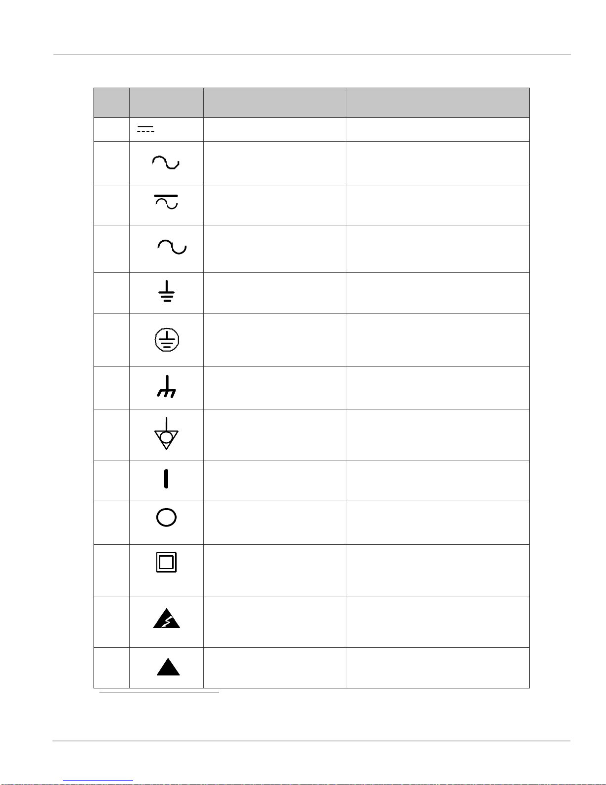
TABLE 1. Safety Symbols and Definitions
No. Symbol Reference Document Definitions
1 IEC 417, No. 5031 Direct current
2 IEC 417, No. 5032 Alternating current
3 IEC 417, No. 5033 Both direct and alternating current
4 IEC-617-2,
No. 02-02-06
Three-phase alternating current
5 IEC 417, No. 5017 Earth (ground)
TERMINAL
6 IEC 417, No. 5019 PROTECTIVE CONDUCTOR
TERMINAL
7 IEC 417, No. 5020 Frame or chassis
TERMINAL
8 IEC 417, No. 5021 Equipotentiality
9 IEC 417, No. 5007 On (Supply)
10 IEC 417, No. 5008 Off (Supply)
11 IEC 417, No. 5172 Equipment protected throughout by
DOUBLE INSULATION or
REINFORCED INSULATION.
1
1. Equivalent to Class II of IEC 536, See annex. H.
12 ISO 3384, No.8.3.6 Caution: risk of electric shock.
14 ISO 3384, No.8.3.1 Caution: refer to the referenced
documents.
3
!

Page
10
Versalight™ OWR User’s Guide
Preface Safety Symbols and Definitions
Software Version 1.0.1
Safety Symbols and Definitions
The Optical Wavelength Router (OWR) unit is designed to comply with the following industr y an d
regulatory standards.
Network Element Product Level
The OWR meets or exceeds the following specification standards.
Network Building Systems (NEBS) Requirements: Physical Level
SR-3580, NEBS Level 3
Network Equipment Building Systems (NEBS)
Requirements: Physical Protection
Telcordia GR-63-CORE
Electromagnetic Compati bility and Electrical Safety - Generic Criteria for Network
Telecommunications Equipment
Telcordia GR-1089-CORE
Safety of Information Technology Equipment including Electrical Business Equipment
Underwriter’s Laboratory UL60950, 3rd edition
Radio Frequency Devices Unintentional Radiators, Commercial Environment
FCC Part 15, Subpart B, Class A
Rack Panel Mounting Standards (Telco 1-inch pitch hole mounting also included)
ANSI/EIA-RS-310C, IEC 297-1

Page
11
Versalight™ OWR User’s Guide
Equipment Specifications Preface
Software Version 1.0.1
Equipment Specifications
This section lists the physical, electrical, optical, and environmental specifications for the
Versalight™ OWR.
Physical Specifications
Table 2 lists physical specifications.
TABLE 2. Physical Specifications
Electrical Specifications
Table 3 lists electrical specifications.
TABLE 3. Electrical Specifications
Electrical Connections
Table 4 lists electrical connections.
TABLE 4. Electrical Connections
Characteristic Specification
Height 3.5 inches (8.9 cm) (2U tall)
Width 16 inches (40.6 cm)
Depth 12 inches (30.5 cm)
Weight 12.5 lbs (5.67 kg)
Characteristic Specification
Power Requirement <5 W
Power Options –48 V DC or +24 V DC power with optional
redundant DC power supplies.
Characteristic Specification
Power Cable Gauge #18 AWG used with a flanged spade
terminal. Required AMP 322777 or
equivalent.

Page
12
Versalight™ OWR User’s Guide
Preface Equipment Specifications
Software Version 1.0.1
Drain Specifications
Table 5 lists drain specifications.
TABLE 5. Drain Specifications
Optical Specifications
Table 6 lists optical specifications.
TABLE 6. Optical Specifications
VOWR2020 MAXIMUM
Single Supply -48V @ .100 A typical.
+24V @ .180 A typical.
Dual Supply -48V @ .123 A typical.
-24V @ .222 A typical.
Characteristic Specification
Number of Channels 20
Channel Plan Customer specified channels on ITU C-band grid,
or Lightchip™ Standard:
CH1 1530.334 nm to CH20 1560.606 nm
NOTE: Refer to the Test Data Sheet for the op tical
specifications of the unit.
Channel Spacing 200 GHz (1.6 nm) for the LC-OWR-2020 model.
Fiber Connector Style SC/UPC, SC/APC standard (other connector
styles are available).
Note: Standard optical monitor ports are SC/APC.

Page
13
Versalight™ OWR User’s Guide
Preface
Software Version 1.0.1
Environmental Specifications
Table 7 lists environmental specifications.
TABLE 7. Environmental Specifications
Characteristic Specification
Operating Temperature –5
o
C (23o F) to 65o C (158o F)
Relative Humidity 5% to 85%
Altitude 60 m (197 ft) below sea level to 1800 m (5905 ft) above
sea level
Non-Operating (Storage/Transport)
Temperature
–40
o
C (–40oF) to 85o C (185o F)
Temperature/Humidity 40
o
C (104o F) at 95% relative humidity

Page
14
Versalight™ OWR User’s Guide
Preface
Software Version 1.0.1

Page
15
Versalight™ OWR User’s Guide
Physical Description Overview
Software Version 1.0.1
CHAPTER 1
Overview
This chapter provides an overview of the Versalight™ Optical Wavelength Router (OWR) and
includes physical and functional descriptions of the OWR.
FIGURE 1. Versalight™ Optical Wavelength Router (OWR)
Physical Description
The Versalight™ OWR is a 2 rack unit or (3.5 inches/8.9 cm high, 16 inches/40.6 cm wide, and 12
inches/30.5 cm deep) rack-mountable assembl y, designed to mount on a standard 19-inch or
23-inch EIA equipment mounting rack.
Each OWR unit contains:
• An optical multiplexer/demultiplexer assembly
• Single/dual DC power supply
• A control processor
• A front panel alarm cutoff switch
• Front and rear panel status indicators
• Front panel optical connectors
• Rear panel electrical connectors
The OWR unit weighs 12.5 pounds (21 pounds shipping weight in the unit’s shipping container).
Functional Description
The Versalight™ OWR utilizes a classic diffraction grating desi gn to provide full, single-fiber
bidirectional functionality in a cost-effective shelf. The OWR is designed to multiplex up to 20
wavelengths from the ITU C-band into a multi-wavelength DWDM signal, while simultaneously
demultiplexing a multi-wavelength DWDM signal in the opposite direction. The unit features a highly
reliable passive optical design which requires no electrical power to maintain optical performance.
The LC-OWR-2020’s channel spacing is 200 GHz (1.6 nm), making 20 th e total number of channels
available in either direction.

Page
16
Versalight™ OWR User’s Guide
Overview Functional Description
Software Version 1.0.1
The OWR optical design offers extremely high performance across the ITU’s C-band channel grid,
making it compatibl e with a var iety of network appl ications. The uni t’s very low signal l oss, low power
requirement (<5 W), and simple instal lation, make it easy to integrate into existing networks.
The OWR unit can be interfaced with the Versalight™ Optical Wavel ength Manager (OWM) via an
LC DEV-A/B RS-485 (hereafter referred to as LC-485) device management bus and supports the
OWM’s LC-485 bus auto-discovery feature. When deployed in conjunction with an OWM, the OWR
provides a full range of signal and loss-of-power alarms.
The RS-232 (CRAFT) port is used to set up the unit and retrieve status information defined by the
CLI commands.
The athermal design of the OWR allows the unit to operate over a temperature range from –5°C to
65°C and eliminates the need for temperature compensation.
The unit may be ordered with a –48 V DC or +24 V DC power supply. An optional –48 V DC or +24 V
DC backup supply is also available. These power supplies pr ovide power for t he front and rear panel
LEDs and the alarm reporting relays. The passive optical core assembly continues to operate when
power is lost; therefore, it continues to provide an uninterrupted path for data traffic flowing through
the unit.
Page
17
Versalight™ OWR User’s Guide
Front Panel Hardware Components
SoftwareVersion: 1.0.1
CHAPTER 2
Hardware Components
This chapter contains descriptions of the hardware components of the Versalight™ Optical
Waveleng th Router (OWR) including physical, electrical, and power characteristics. This chapter
includes:
• Front Panel
– Front Panel Connections
– Front Panel Controls and Indicators
• Rear Panel
– Rear Panel Connections
– Rear Panel Controls and Indicators
Front Panel
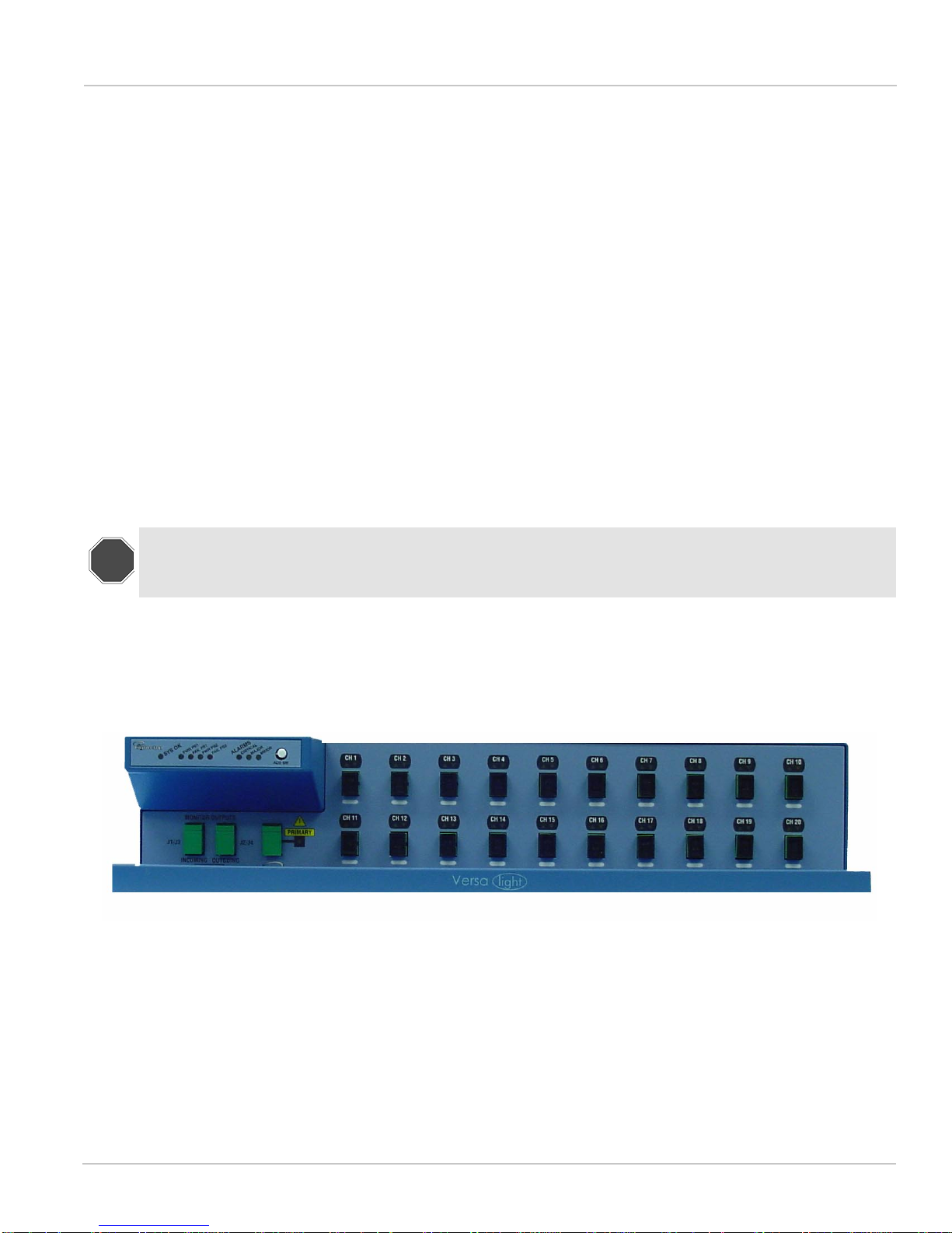
Figure 2 ‘’Front Panel of the Versalight™ OWR‘’ depicts the front panel of the Versalight™ Optical
Waveleng th Router (OWR) unit. The front panel provid es SC quick-connect optical connectors for
connecting the unit to a network’s optical fiber spans. The unit’s front panel also includes si gnal
activity indicators, shelf alarm indicators, and an alarm cutoff switch.
FIGURE 2. Front Panel of the Versal ight™ OWR
STOP!
Laser light hazard. Never look into the end of an opti cal fiber or connector. DWDM signals can equ al
the combined output of up to 20 lasers. Failure to observe this warning can result in eye damage
and blindness.
Page
18
Versalight™ OWR User’s Guide
Hardware Components Front Panel
SoftwareVersion: 1.0.1
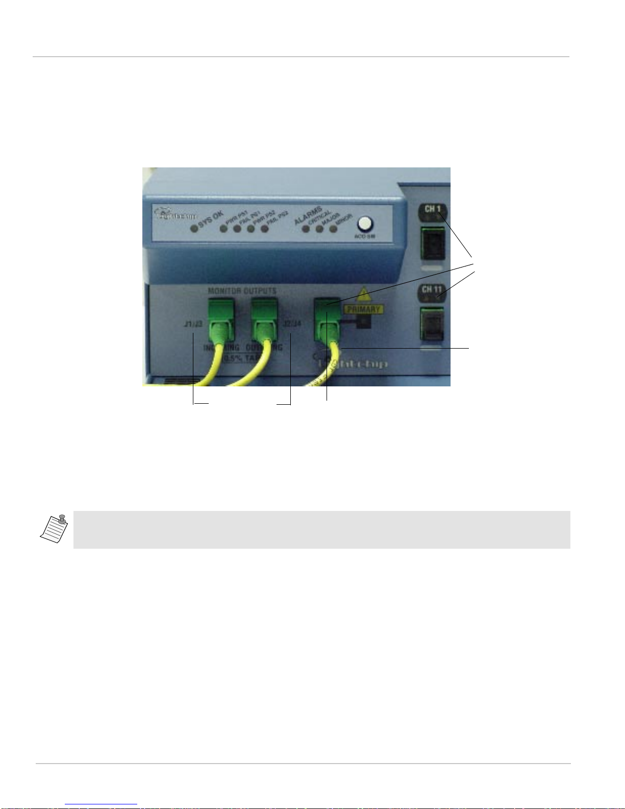
Front Panel Connections
To make the connections shown in Figure 3 ‘’Front Panel Cable Connections‘’ use any single-mode
fiber optic patch cords equipped with connectors.
FIGURE 3. Front Panel Cable Connections
1. Connect the fibers to the optical connectors on the front panel of the OWR.
2. If the OWR is monitored by the OWM unit, r oute f iber o ptic patchcords from the INCOMING and
OUTGOING monitor port to the respective INCOMING and OUTGOING ports on the OWM.
Several OWR’s may be monitored using the 8 port OWM.
Front Panel Controls and Indicators
This section describes the controls and indicators on the front panel of the OWR. Keep in mind that
the unit is designed to operate in conjunction with the signal monitoring functions performed by a
Versalight™ OWM unit. Many of the front panel indicators on the OWR are controlled by data
supplied to the OWM via the LC-485 dev ice management bus, and are a ctive only when the OWR i s
interfaced to an OWM.
Input wavelengths must be connected to the connector labeled with the same wavelength.
Monitor
Connectors
Common
I/O Connector
Fiber Optic
Patch Cord
SC
Connectors
Page
19
Versalight™ OWR User’s Guide
Front Panel Hardware Components
SoftwareVersion: 1.0.1
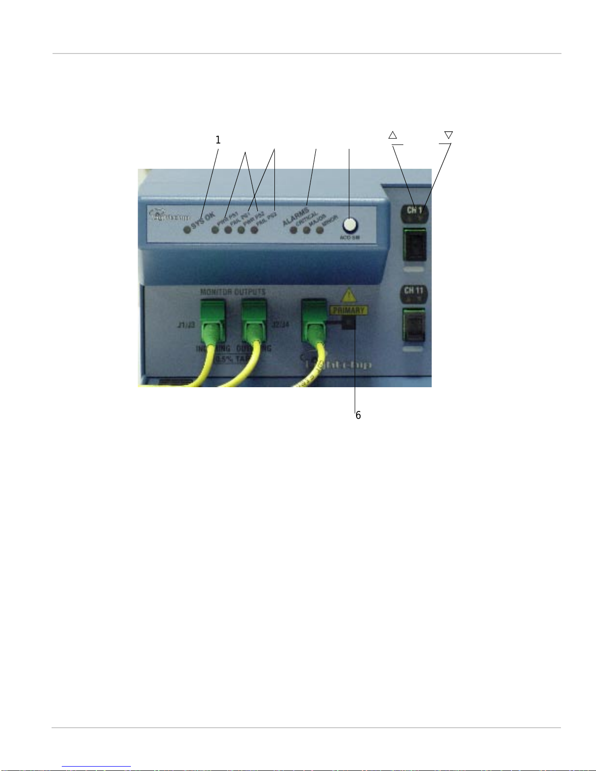
Figure 4 ‘’Front Panel Controls and In dicator s‘’ i llust rates the front p anel co ntrols and i ndicator s. The
numbers on the diagram are referenced in Table 8.
FIGURE 4. Front Panel Controls and Indicators
7
U
V
6
1 2 3 4 5
 Loading...