

Page 1
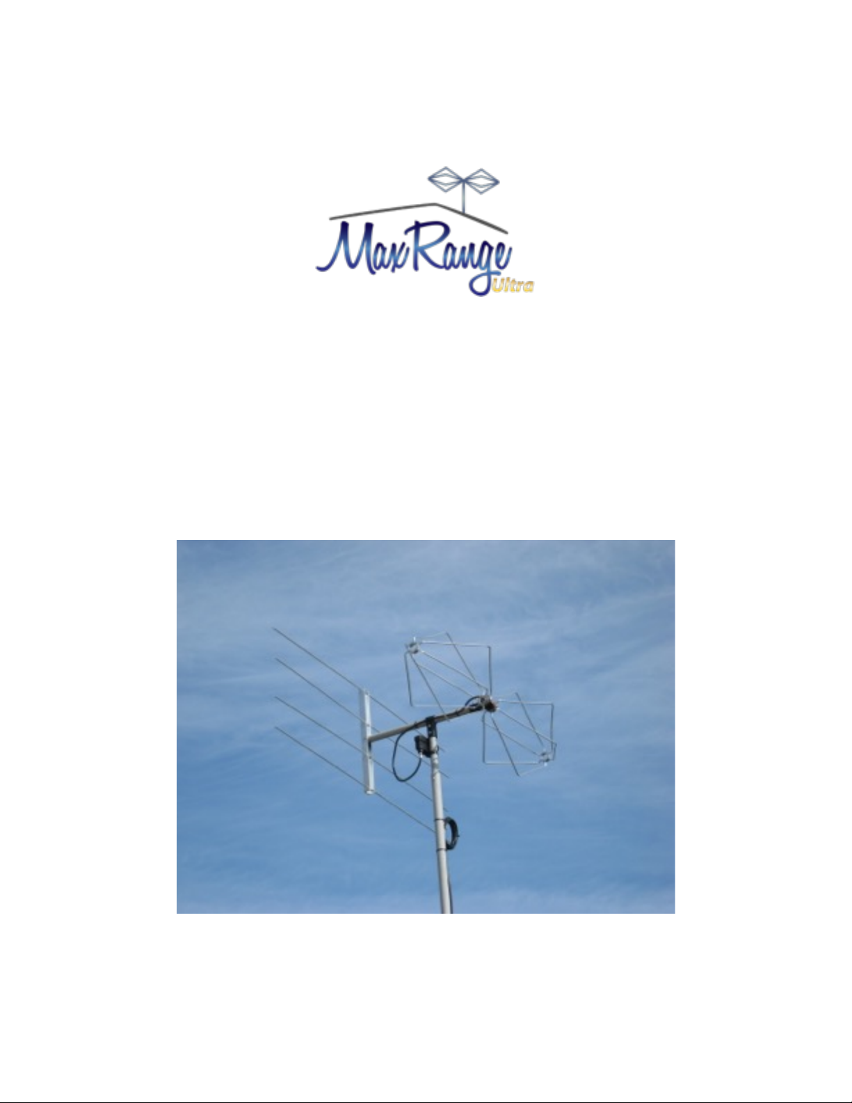
LIGHT BEAM ANTENNA
MaxRange Antenna Series
Assembly Instructions
MaxRange Ultra
Digital / High Definition
Television Antennas
Assembly Instructions
1
MaxRange Ultra Antenna
Page 2
These instructions will lead you through the simple steps needed to
assemble your new antenna. Follow each step to ensure that the
antenna is assembled correctly.
Assemble the antenna on a table or other safe location having
adequate lighting. Work safely, use tools properly and wear eye
protection.
Your antenna is delivered in one box. Inspect the box for damage and notify the
shipping company if damage is visible.
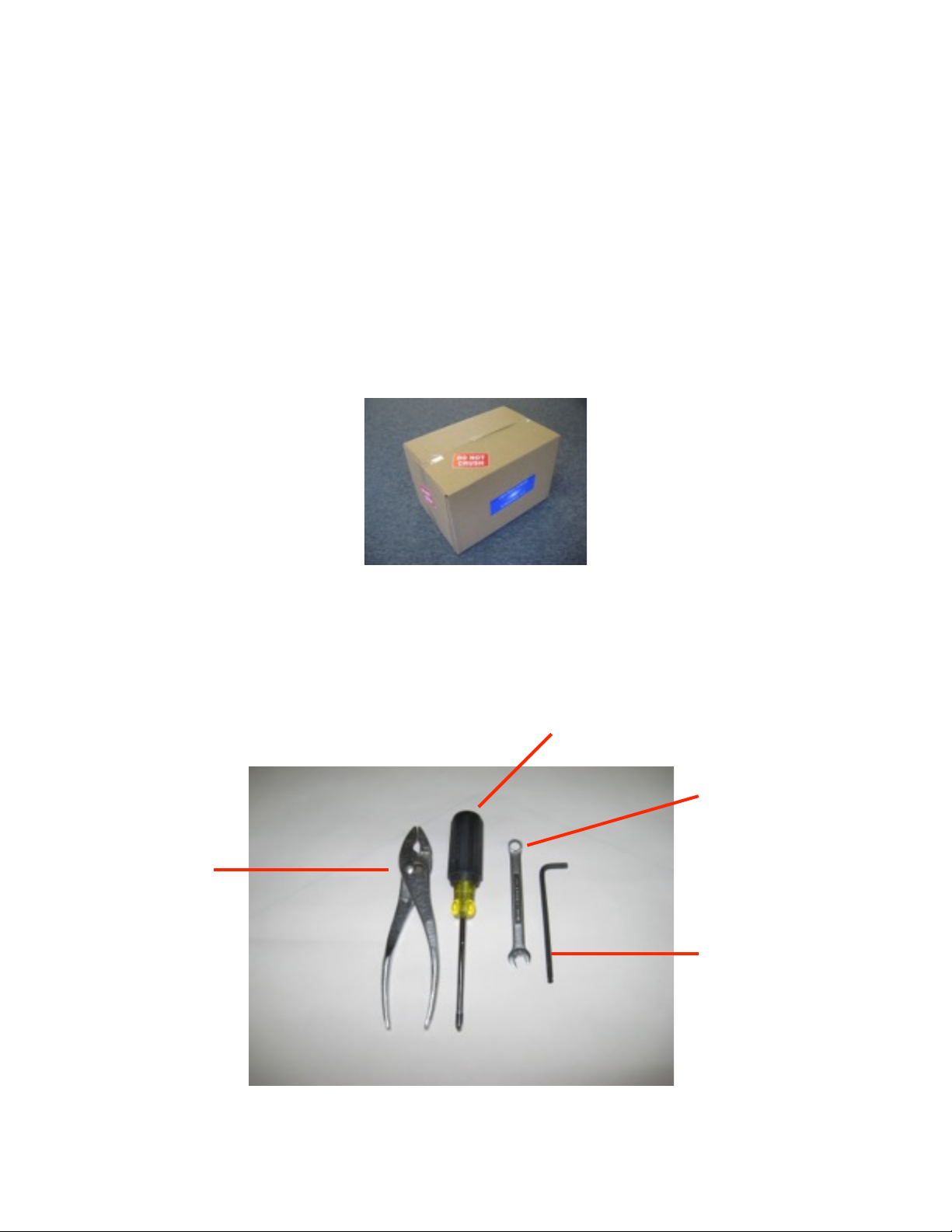
Tools you will need are:
•
Pliers
•
A Philips Screw Driver
•
A 3/8” Nut Wrench
•
A 3/16” Hex Wrench
Assembly Instructions
2
MaxRange Ultra Antenna
Philips
Screw Driver
3/8” Nut
Wrench
3/16” Hex
Wrench
Pliers
Page 3
MaxRange Ultra Antenna Assembly
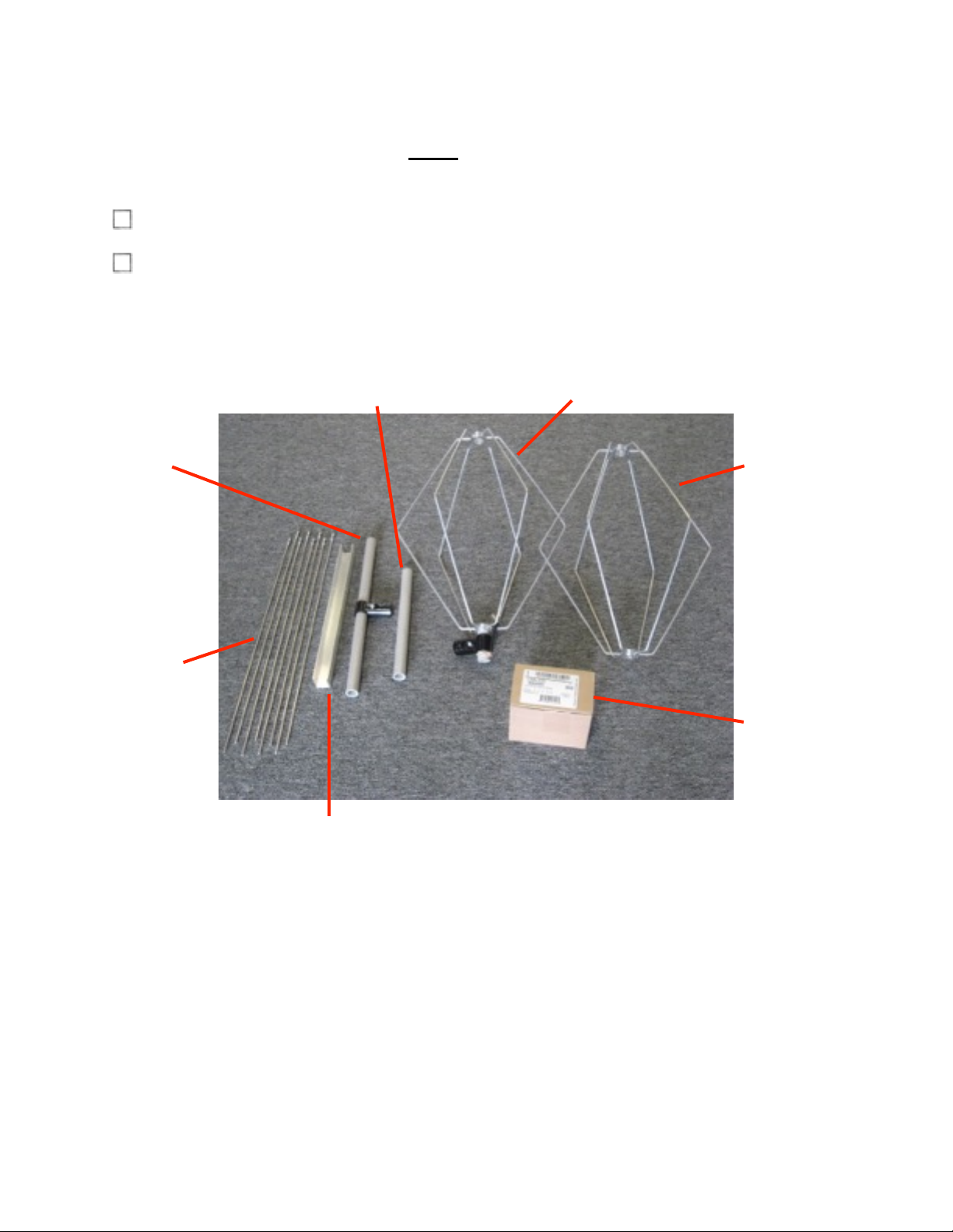
Open the box and remove the antenna component bundle. Inspect for damage.
Carefully remove the plastic wrap and inspect the antenna components.
Assembly Instructions
3
MaxRange Ultra Antenna
Antenna
Element
Mast
Stub
Boom
Reflector
Strut
Reflector
Elements
Low
Noise
Amp.
Antenna Element
with Coupling
Page 4
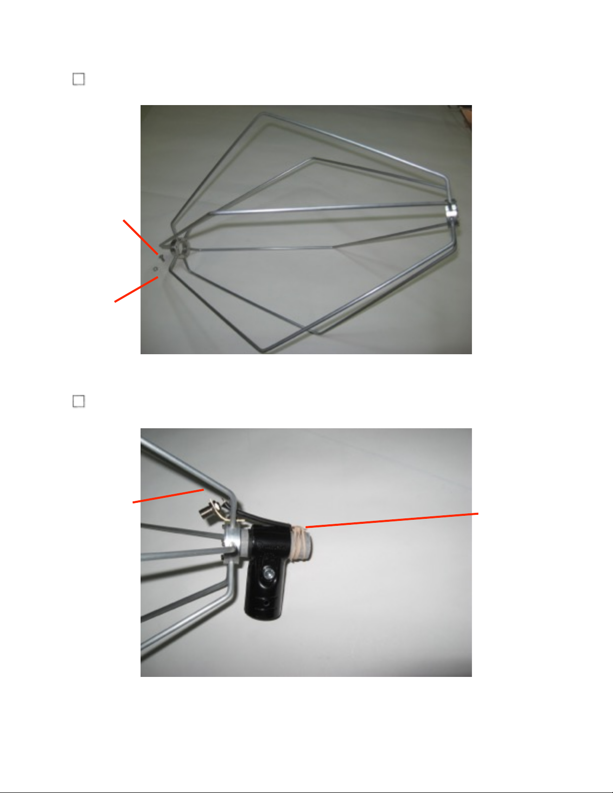
Select the Antenna Element and remove the 10-24x 1/2” screw and star washer.
Select the Antenna Element with Coupling and carefully remove the Elastic Band.
Assembly Instructions
4
MaxRange Ultra Antenna
10-24
Screw
Star
Washer
Antenna
Element
with
Coupling
Elastic
Band
Page 5

Carefully slide the Antenna Element onto the Coupling as shown, under the Terminal
Strip. Align the screw hole of the Antenna Element Hub with the hole in the Coupling
Tube and then insert the 10-24x 1/2” Screw as shown through the Terminal Strip,
and Star Washer. Tighten firmly the 10-24x 1/2” Screw into the Antenna Element
Hub.
!
Assembly Instructions
5
MaxRange Ultra Antenna
Antenna
Element
with
Coupling
Terminal
Strip
10-24
Screw
Star
Washer
Antenna
Element
Hub
Coupling
Tube
Antenna
Element
Page 6
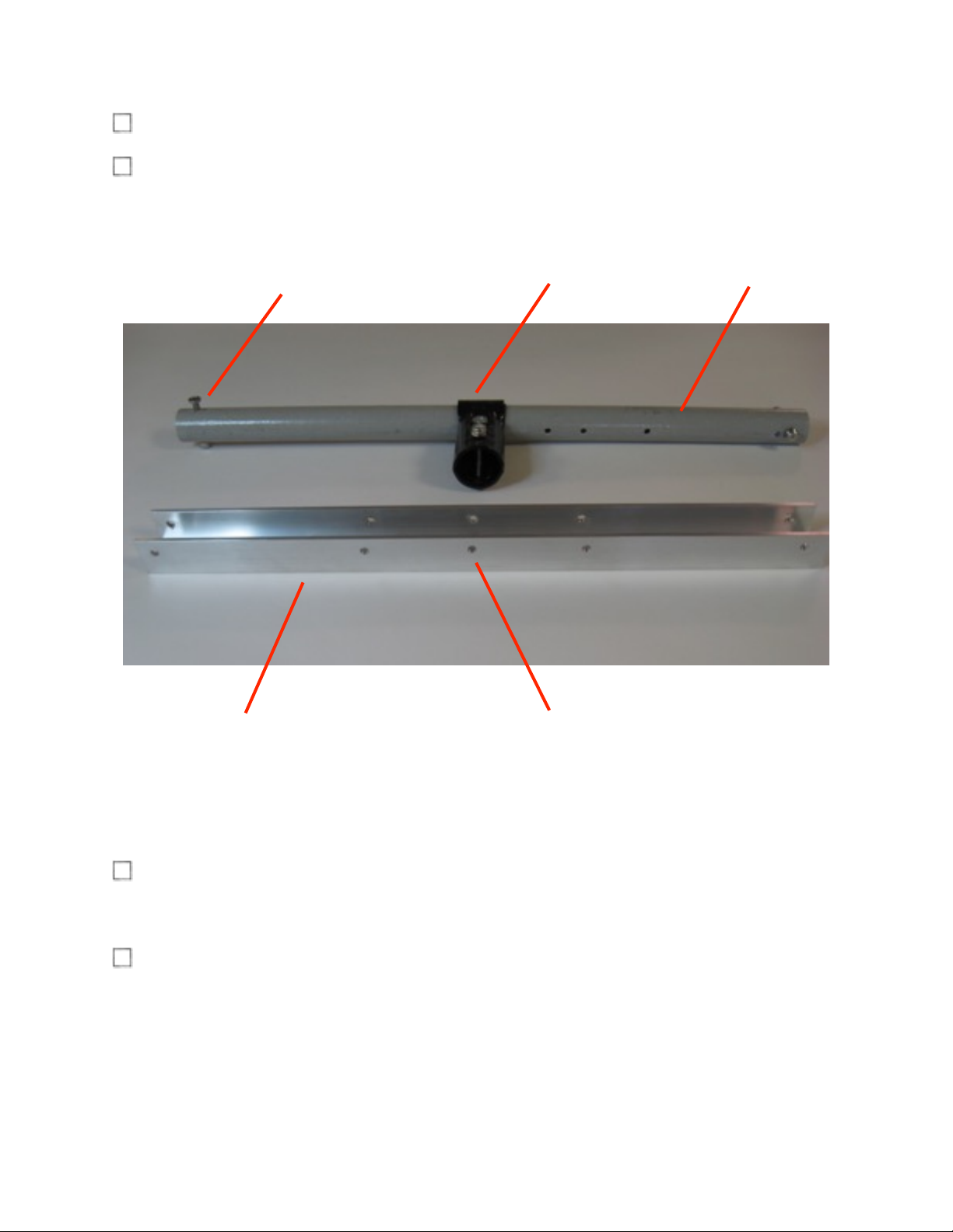
Orient the Boom as shown below. Note the position of the Boom Coupling
Using a Phillips Screwdriver, loosen and remove the indicated 10-24x1-1/2” screw
and 10-24 anti-vibration hex-nut from the Boom.
Insert the Boom into the Reflector Strut channel at the center hole and align the
holes in the Reflector Strut with the holes in the Boom.
Insert the 10-24x1-1/2” screw through the Reflector Strut and Boom. Firmly tighten
the 10-24 anti-vibration hex nut.
Assembly Instructions
6
MaxRange Ultra Antenna
Boom
Boom Coupling
Screw & Hex Nut
(Remove this screw)
Reflector Strut
Boom Mounting Hole
(Center Hole)
Page 7
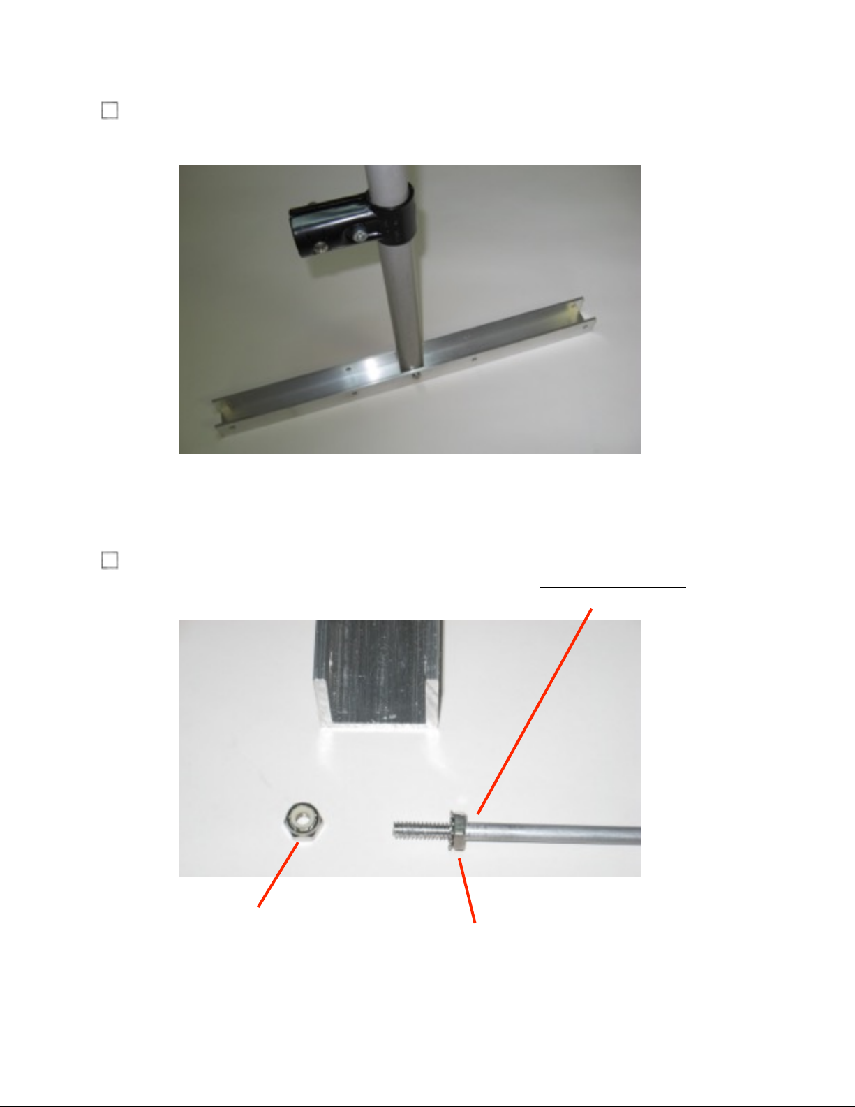
Position the Reflector Strut as shown with the Boom in a vertical position.
Collect the Reflector Elements (Qty. 8) and remove the 10-24 anti-vibration hex nut
from each element. Turn the 10-24 hex nut with washer fully onto each rod.
Assembly Instructions
7
MaxRange Ultra Antenna
10-24 anti-vibration
hex nut
10-24 hex nut with
washer
Page 8
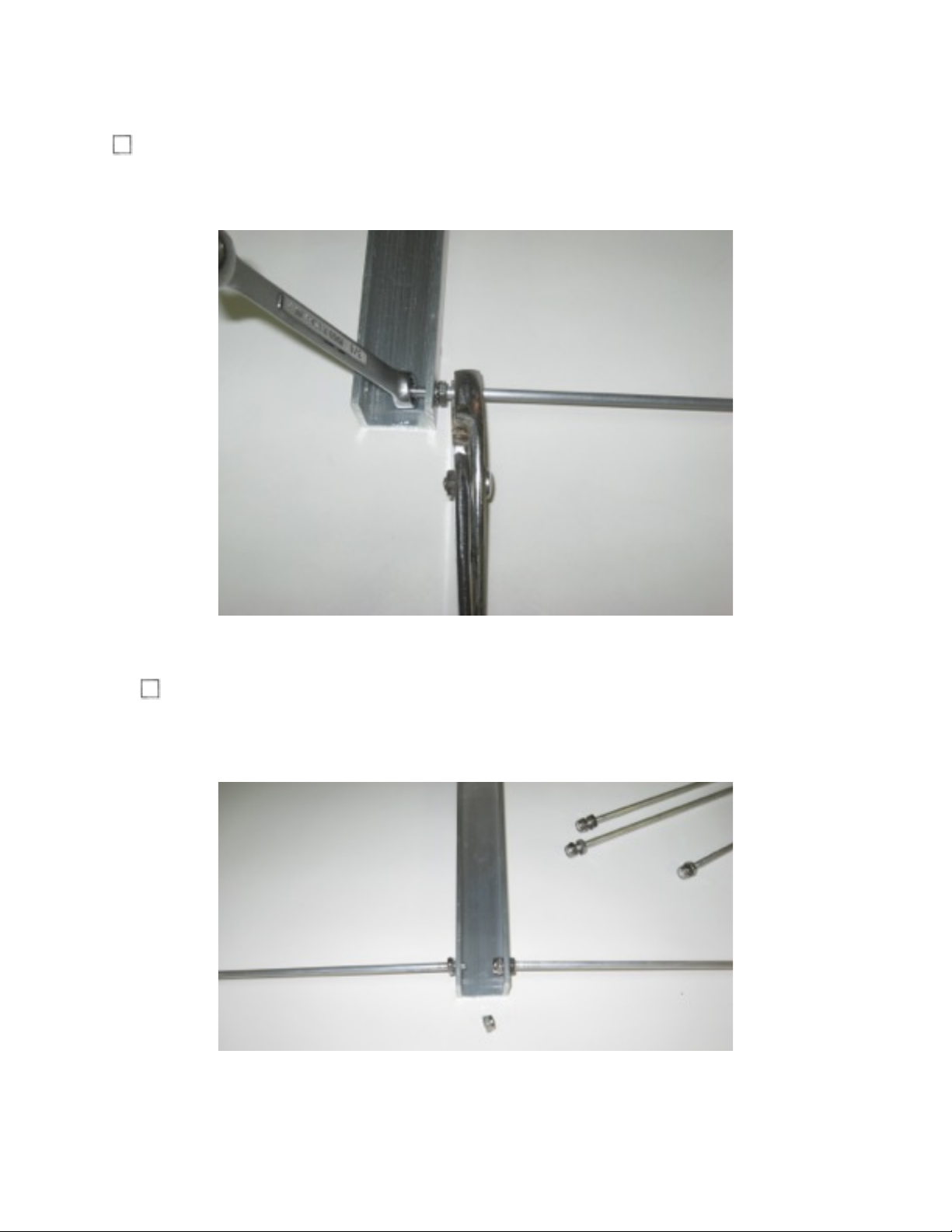
Insert each element into the Reflector Strut and place a 10-24 anti-vibration hex nut
on each Reflector Element as shown. Hold the rod using Pliers. Using the 3/8”
Wrench, turn the nut until snug. Do not over-tighten.
Repeat the previous step and insert each of the remaining elements into the
Reflector Strut.
Assembly Instructions
8
MaxRange Ultra Antenna
Page 9
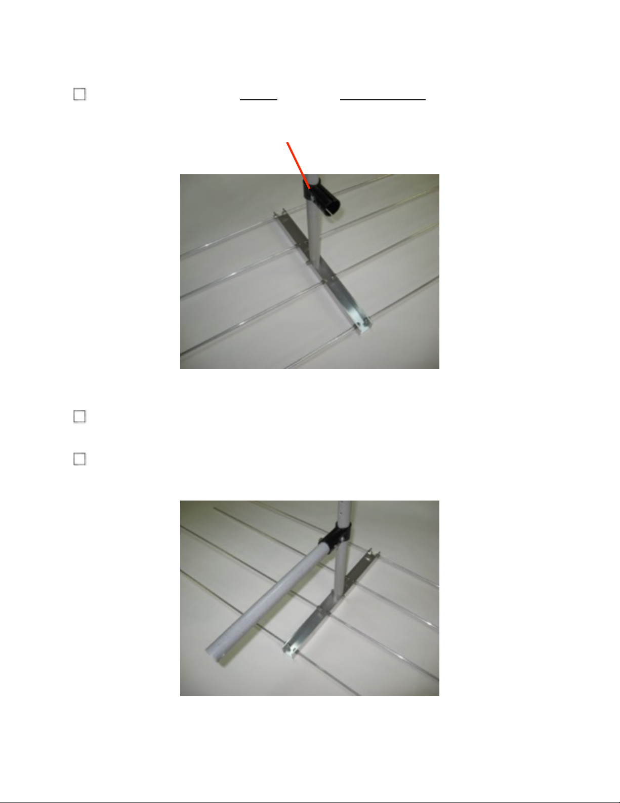
Using a 3/16” Hex Wrench, slightly loosen the hex-head screw in the Boom
Coupling.
Using a Phillips Screwdriver, loosen and remove the 10-24x1-1/2” screw and 10-24
anti-vibration hex-nut from the Mast Stub.
Insert the Mast Stub into the Boom Coupling and align the holes in the Coupling with
the holes in the Mast Stub.
Assembly Instructions
9
MaxRange Ultra Antenna
Hex-Head Screw
Page 10
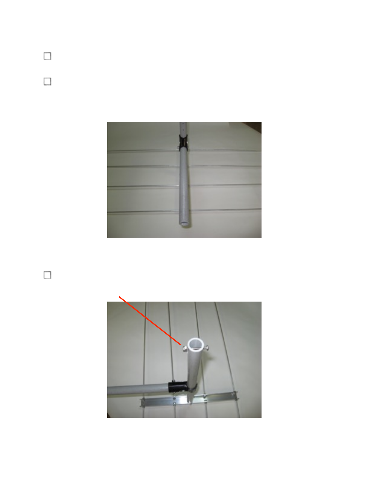
Insert the 10-24x1-1/2” screw through the Coupling and Mast Stub. Loosely tighten
the 10-24 anti-vibration hex nut. Fully tighten after the next step.
Align the Boom to be parallel with the Reflector Strut as shown. Then using a 3/16
Hex Wrench, firmly tighten the Hex Head Screw in the Boom Coupling. See
previous step and firmly tighten the 10-24 anti-vibration hex-nut.
Using a Phillips Screwdriver, loosen and remove the 10-24x1-1/2” screw and 10-24
anti-vibration hex-nut from the Boom.
Assembly Instructions
10
MaxRange Ultra Antenna
Page 11
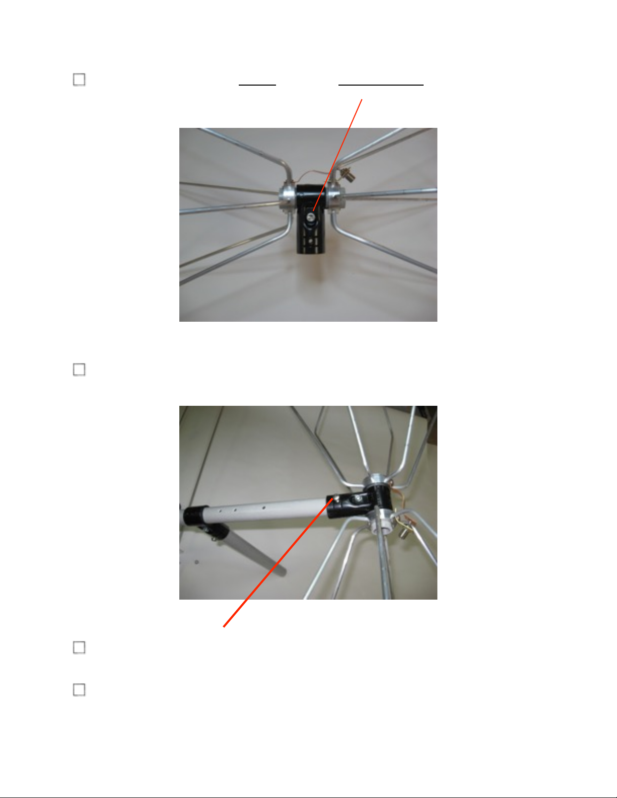
Using a 3/16” Hex Wrench, slightly loosen the hex-head screw in the Antenna
Element Coupling.
Insert the Boom into the Antenna Element Coupling and align the holes in the
Coupling with the holes in the Boom.
Insert the 10-24x1-1/2” screw through the Coupling and Boom. Firmly tighten the
10-24 anti-vibration hex nut.
Firmly tighten the hex-head screw in the Antenna Element Coupling. !
Assembly Instructions
11
MaxRange Ultra Antenna
Page 12
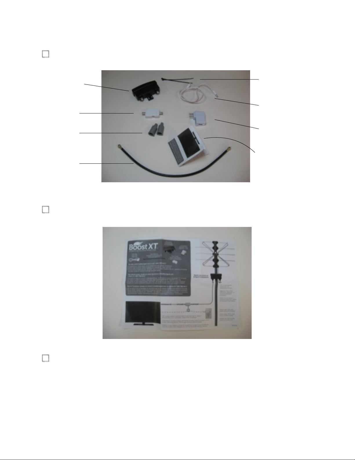
Unpack the small box and inspect the components.
Read the Pre-amplifier Installation Instructions that are included in the small box.
Connect and tighten one end of the short length of RG6 Coaxial cable provided, to
the connector of the antenna. !
Assembly Instructions
12
MaxRange Ultra Antenna
Preamplifier
Power
Inserter
Cable
Boots
USB
Cable
110V
Adapter
Coaxial
Cable
Cable
Ties
Instructions
Page 13
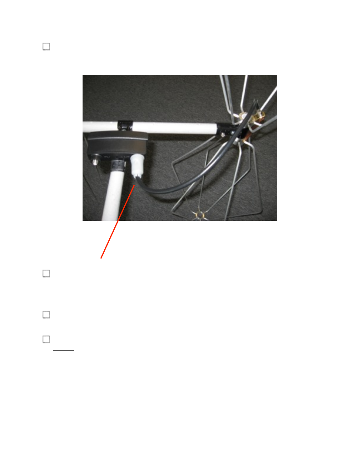
Mount the Pre-amplifier on the Mast Stub of your MaxRange Antenna per the
instructions using the Cable Ties provided.
Weatherproof the other cable end of the short cable by sliding the Cable Boot over
the cable connector. Then connect the cable end with Cable Boot to the “ANT.”
connector of the Pre-amplifier. Tighten the connector and slide the boot up to cover
the Pre-amplifier connector.
The other Cable Boot is used to weatherproof the cable end of the cable that is
connected to the “TV” connector of the Pre-amplifier.
The orientation of the Pre-amplifier should be as shown with the connectors at the
bottom of the Pre-amplifier.
Assembly Instructions
13
MaxRange Ultra Antenna
Page 14
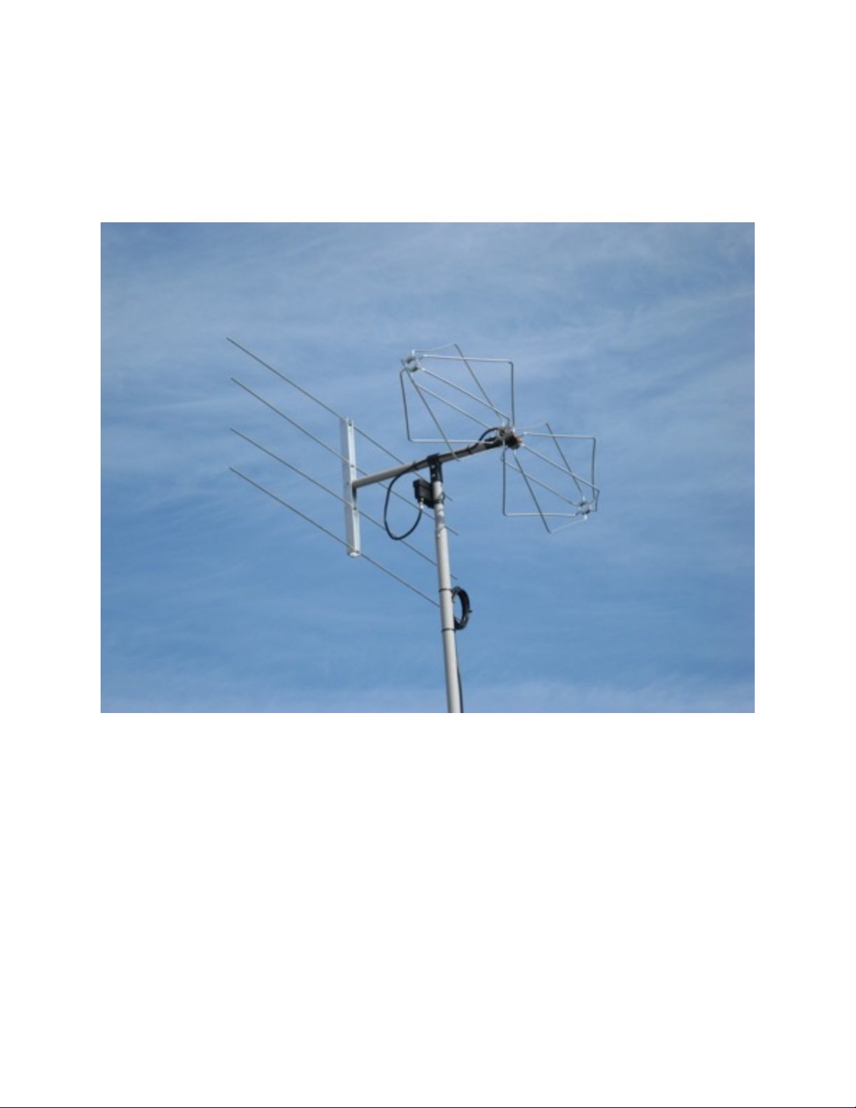
Congratulations, you have completed the assembly of your MaxRange
Ultra Antenna.
Assembly Instructions
14
MaxRange Ultra Antenna
 Loading...