

Page 1
Phantom – Emergency Lighting
WARNING:
Risk of Electrical Shock.
Disconnect Power before Installation.
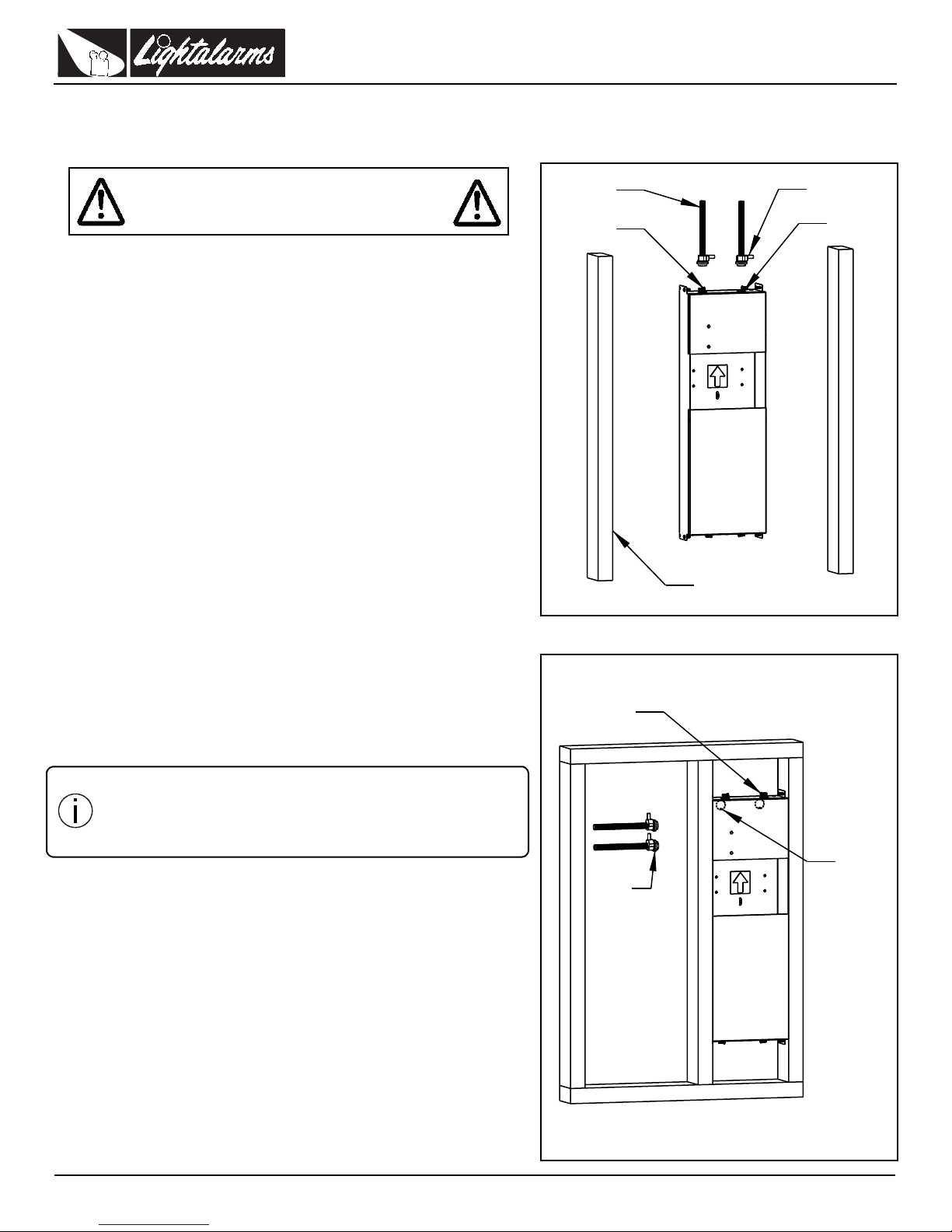
Figure 1
Conduit
(4) Mounting
Screws
Conduit
Bushing
Wall Mount
Knock Out
2 x 4 Stud
Figure 2
(4) Mounting
Screws
Conduit
Conduit
Bushing
Ceiling
Mount
Knock Out
IMPORTANT SAFEGUARDS
When using electrical equipment, basic safety precautions should always be
followed including the following:
READ AND FOLLOW ALL SAFETY
INSTRUCTIONS
1. All servicing should be performed by qualified service personnel.
2. All unused wires must be insulated to prevent shorting.
3. Do not use outdoors.
4. Do not let power supply cords touch hot surfaces.
5. Do not mount near gas or electric heaters.
6. Use caution when handling batteries. Avoid possible shorting.
7. Equipment should be mounted in locations and at heights where it will
not readily be subjected to tampering by unauthorized personnel.
8. The use of accessory equipment not recommended by the manufacturer
may cause an unsafe condition.
9. Do not use this equipment for other than intended use.
10. Unit to be installed only as per configuration described in this instruction
manual.
Phantom – Emergency Lighting
SAVE THESE INSTRUCTIONS
Installation Instructions
Turn off AC power.
Wall Mount Back-Box Installation (Figure 1)
1. Knock out the hole(s) on top of the back-box for incoming cable(s) (AC
2. Position the back-box at the desired location to be flush with the front
3. Use appropriate fasteners (not supplied) to mount the back-box on the
4. Connect the conduit to the K.O.’s on the top of the box.
5. Pull 10” of wire into the box for the final electrical connections.
6. Install the drywall over the back-box.
7. Locate the center of the opening and rout out drywall. Follow the outline
Install fixture/lamp type combination no higher than
the maximum mounting heights as stipulated in the
IMPORTANT:
line and/or DC emergency line). (Figure 1)
edge of the stud observing mounting orientation (Figure 1).
stud (Figure 1).
of the opening in the back-box.
“Lamp Mounting Height Cross-reference Table” (P/N
750.1924). Refer to “Technical Information” section
of our website.
LightAlarms Tel: (888) 552-6467 Fax: (800) 316-4515 www.lightalarms.com
09/16 750.1305 Rev . C
1/4
Page 2
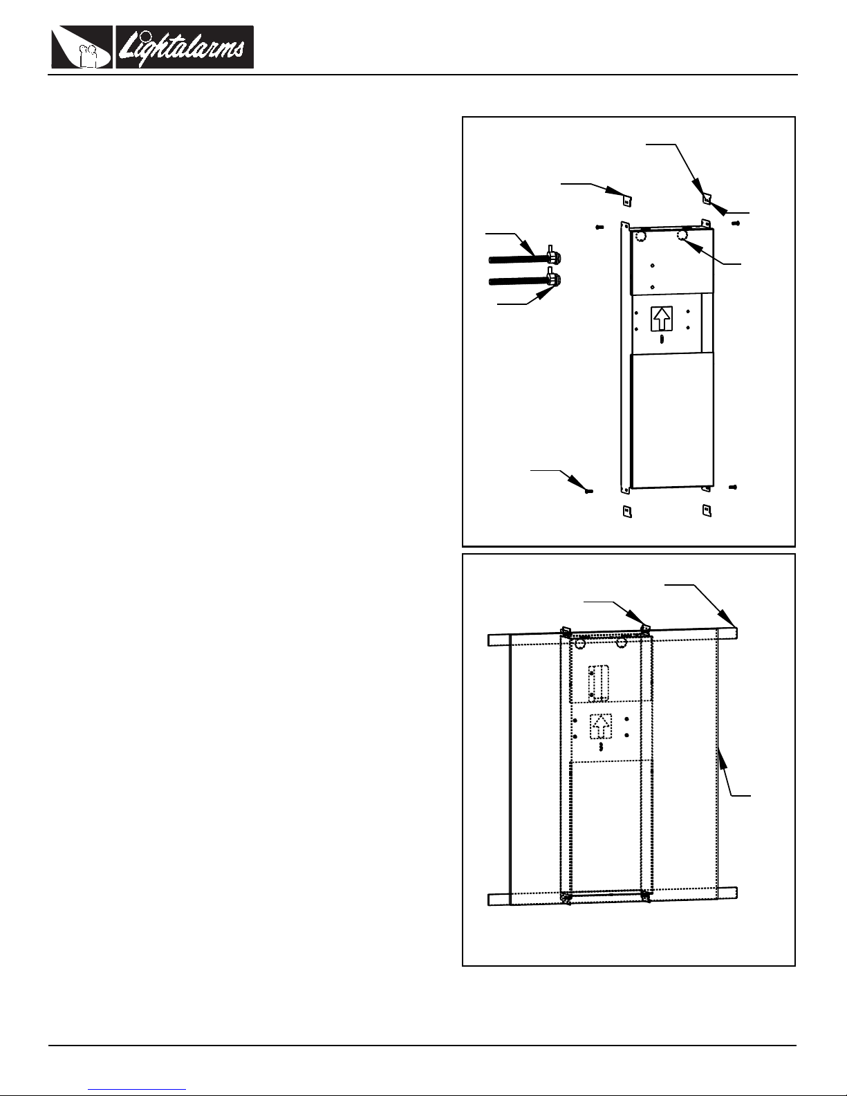
Drywall Ceiling Back-Box Installation (Figure 2)
Figure 3
T-Bar Brackets
Position#1
Position#2
(4) Mounting
(Move to adjust
tile thickness)
Screws
for ceiling
Conduit
Conduit
Bushing
Ceiling
Mount
Knock-Out
Figure 4
T-Bar Brackets
Ceiling
T-Bar
Ceiling
Tile
1. Knock out the hole(s) on the back-box for incoming cable(s). (AC line
and/or DC emergency line, Figure 2).
2. Position the back-box at the desired location to be flush with the front
edge of the joist, observing mounting orientation (Figure 2).
3. Mount the back-box on the joist using screws (not supplied).
4. Frame the back-box as shown in Figure 2. Check for proper installation.
5. Follow instructions 5 to 9 of the Wall Mount Back-Box Installation.
T-bar Ceiling Back-Box Installation (Figure 3)
1. Knock out the hole(s) on the rear of the back-box for incoming
cable(s). (AC line and/or DC emergency line) (Figure 3).
2. Mount the supplied T-bar brackets on the four tabs as shown in the
Figure 3. Use position #1 hole for 1” T-bar and position #2 hole for
1.5” T-bar. For each position move the bracket to adjust the slot
hole(s) for 1/2” or 5/8” ceiling tile thickness to locate the back-box
flush with the back face of the ceiling tile. Tighten the screw(s).
3. Position the back-box at the desired location across the ceiling Tbars (Figure 4). Secure the Back-Box to the ceiling joists by chains,
or “pencil rod” wire to support the unit.
4. Follow instructions 5 to 7 of the Wall Mount Back Box Installation.
5. Install the ceiling tile in position. There should not be any gap
between the back-box and the tile if the mounting brackets have
been installed properly.
6. Locate the center of the opening and route out the ceiling tile. Follow
the outline of the opening of the back-box.
Phantom – Emergency Lighting
LightAlarms Tel: (888) 552-6467 Fax: (800) 316-4515 www.lightalarms.com
09/16 750.1305 Rev. C
2/4
Page 3
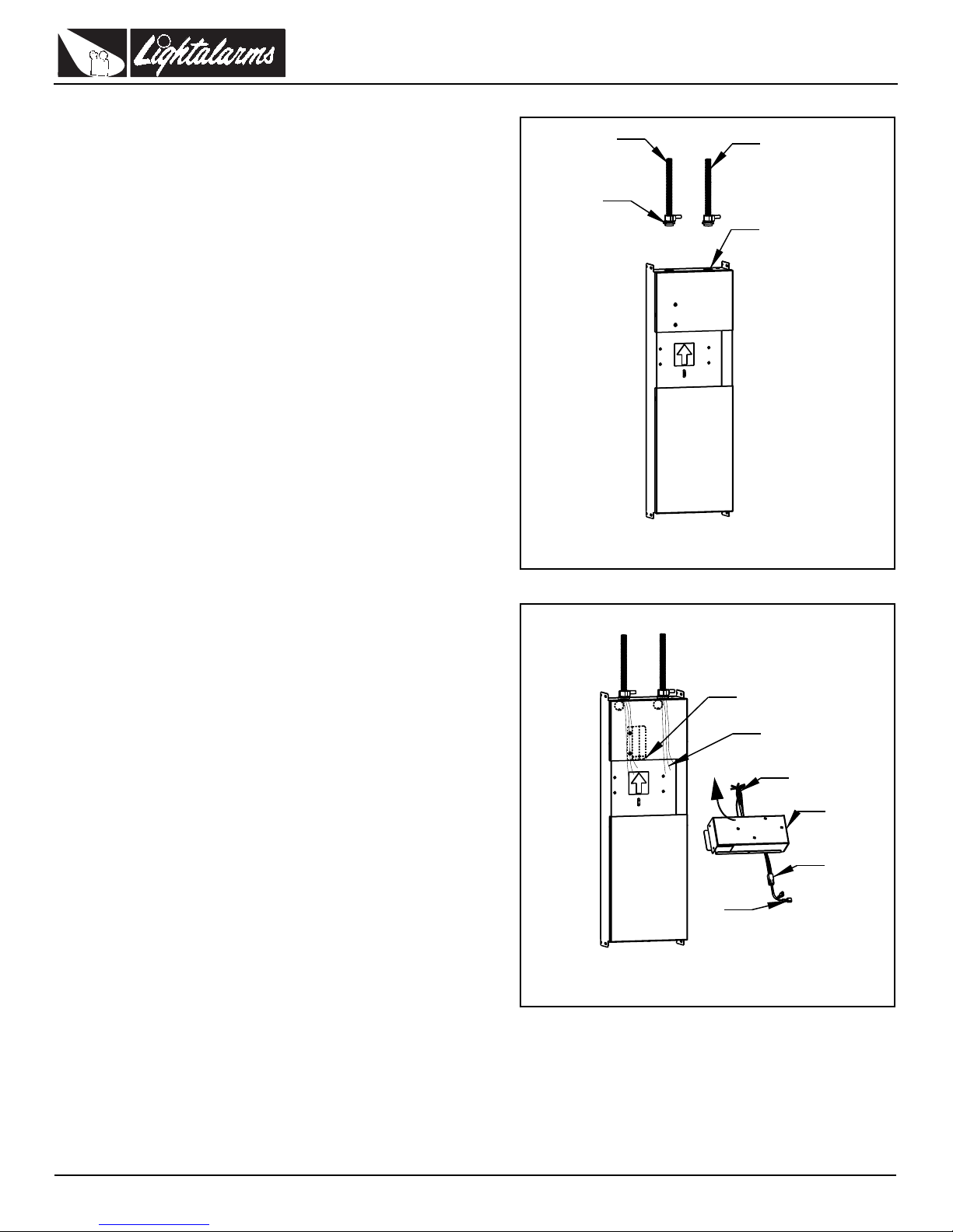
Charger Module Installation (Figure 6)
Figure 5
AC Supply
DC Supply
(If required)
Wall Mount
Knock Out
Conduit
Bushing
Figure 6
Upper
Compartment
Middle
Lower
Compartment
Compartment
To Charger
Module
To Incoming
Wires
Charger
Module
To Battery
To Lamp
Module
Flexible bracket
1. Pull out the electrical cables from the back box and cut the wires to
leave 2 to 3 inches of wire outside the back-box.
2. Connect the GREEN wires from the charger module and the backbox to the GROUND supply wire.
3. For 120VAC connect the BLACK wire (labeled 120VAC) from the
charger module to Line and the WHITE wire (labeled neutral) to Neutral.
4. For 277VAC connect the ORANGE wire (labeled 277VAC) from the
charger module to Line and the WHITE wire (labeled Neutral) to Neutral.
5. For 347VAC connect the RED wire (labeled 347VAC) from the charger module to Line and the WHITE (labeled Neutral) to Neutrall.
6. If there are any remote heads to be connected to the unit, connect
the RED wire (labeled L+) and the BLUE wire (labeled L-) to the load
out going wires.
7. Caution: failure to cap the wires may cause an unsafe condition
8. Place the charger module in the back-box with the outcoming wires
on the right side. Enter the module at an angle, to bypass the flexibale bracket in the back-box; then slide the module upward, until it is
latched by the flexible bracket. (Figure 6).
9. Check for secure installation.
Phantom – Emergency Lighting
Battery Installation (Figure 7a, b, c)
This equipment is provided with a battery module made up of one, twoor
three sealed batteries, depending on the rated capacity. Follow the
instructions below for the battery module configuration of your unit.
One-battery module (Figure 7a)
1. Take the 2 wires from the charger module (labeled: BATTERY CON-
2. Tighten the tie-wrap next to the battery terminals in order to secure
3. Place the battery in the lower compartment of the back-box, ensuring
4. Place the two wires under the stopper bracket then slide the bracket
Two-battery module (Figure 7b)
1. Take the battery with the wiring harness attached. Verify if the wire
2. Place the battery in the lower compartment of the back-box, with the
3. Take the second battery and run the wires with the female connectors
4. Tighten the tie-wrap next to the battery terminals in order to secure
5. Place the second battery in the same direction as first battery.
6. Connect the male connectors of the wiring harness to the RED and
7. Place the two wires under the stopper bracket then slide the bracket
NECTION) pass them under the tie-wraps and connect them to the
battery (RED to positive and BLUE to negative).
the wires in place.
that the battery terminals are facing the left and the wires on the right
side of the back box.
towards the left into the slot all the way in the back-box (Figure 8).
harness is well connected to the battery tab and tightly secured with
the tie-wrap.
tabs to the left and the wire harness to the right side.
under the tie-wraps and connect them to the battery (RED to positive
and BLUE to negative).
the wires in place.
BLUE wires from the charger module, as per the label indication
(RED wire to RED wire;BLUE wire to BLUE wire).
towards the left into the slot all the way in the back-box (Figure 8).
LightAlarms Tel: (888) 552-6467 Fax: (800) 316-4515 www.lightalarms.com
09/16 750.1305 Rev . C
3/4
Page 4
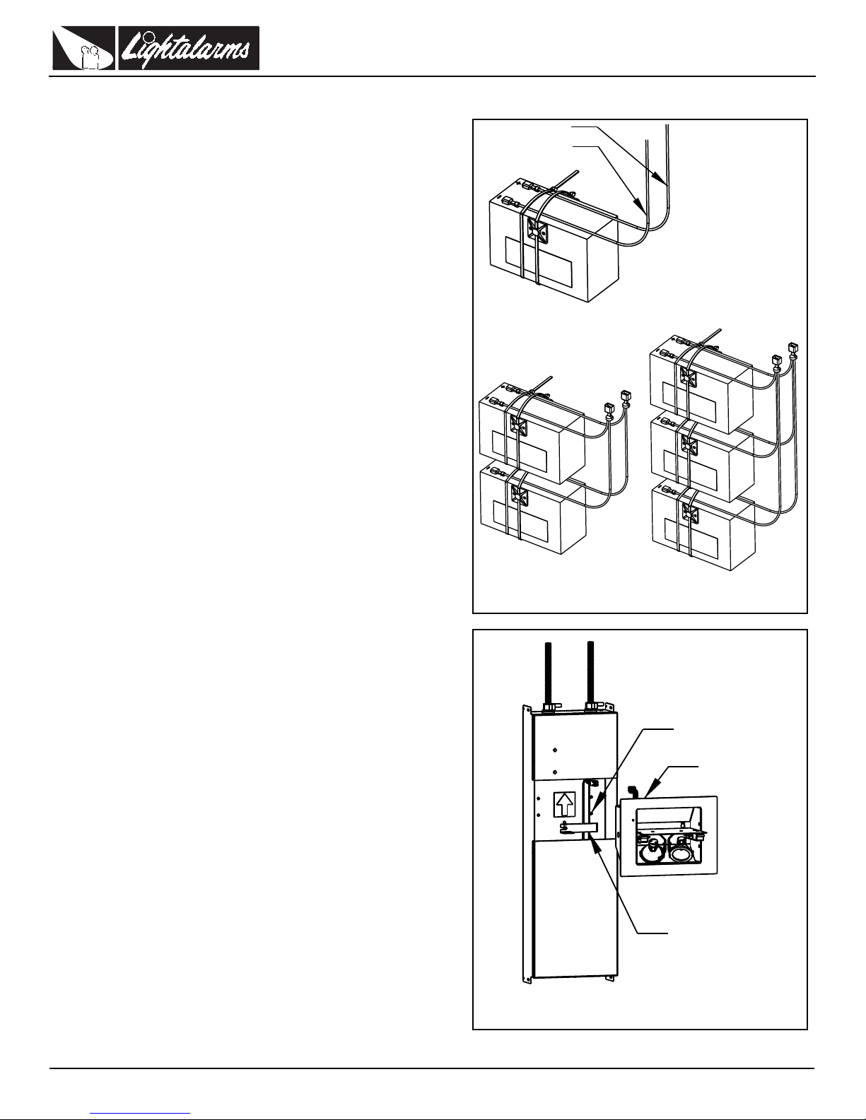
Three-battery module (Figure 7c)
Figure 7 a,b,c
Figure 7a
Figure 7b
Figure 7c
Red
Blue
From
charger
module
}
Figure 8
Stopper bracket
Lamp
Module
Mounting screws
1. Take the battery with the wiring harness attached. Verify if the wire
harness is well connected to the battery tab and tightly secured with
the tie-wrap.
2. Place the battery in the lower compartment of the back-box, with the
tabs to the left and the wire harness to the right side.
3. Take the second battery and run the wires with the female connectors
under the tie-wraps and connect them to the battery (RED to positive
and BLUE to negative).
4. Tighten the tie-wrap next to the battery terminals in order to secure
the wires in place.
5. Place this battery in the same direction as first battery.
6. Take the third battery and run the wires with the female connectors
under the tie-wraps and connect them to the battery (RED to positive
and BLUE to negative). Then follow the same instructions as in steps
4-5 above.
7. Connect the male connectors of the wiring harness to the RED and
BLUE wires from the charger module, as per the label indication
(RED wire to RED wire; BLUE wire to BLUE wire).
8. Place the two wires under the stopper bracket then slide the bracket
towards the left into the slot all the way in the back-box (Figure 8).
Phantom – Emergency Lighting
Lamp Module Installation (Figure 8)
1. Install the four screws (provided with the stopper bracket) 2-3 threads
into the pem-studs of the back-box.
2. Hold the lamp module by the harness and connect it to the 4-pin connector of the charger module.
3. Push on one side of the door of the lamp module to open it half-way
and identify the four key holes in the housing.
4. Mount the lamp module by aligning it with the screws in the back-box.
Slide the lamp module so that the head of the screws are in the slotted part of the key hole. (Make sure the harness and connector are
placed in the space provided between the back-box and the charger
module.)
5. Align the lamp module on the wall then secure it to the back-box by
tightening the four screws (located in the key holes) until its trim is
flush with the wall. (For easy access to the screws the door can be
rotated one full turn of 360 degrees.)
6. Orient the two lamps in their swivels and verify that they are plugged
into the sockets.
7. Close the door and make sure that it is flush with the trim.
Testing the Equipment
1. Energize AC.
2. The recessed pilot light/test switch will light in green.
3. Push the test button. The door will open and the lamps will illuminate
for one minute, then the door will close. Orient the lamps to the
desired position at this time. If more time is needed, push the test
button again.
4. The unit requires no maintence, but should be tested regulary in
accordance with the local codes.
LightAlarms Tel: (888) 552-6467 Fax: (800) 316-4515 www.lightalarms.com
09/16 750.1305 Rev. C
4/4
 Loading...