

Page 1
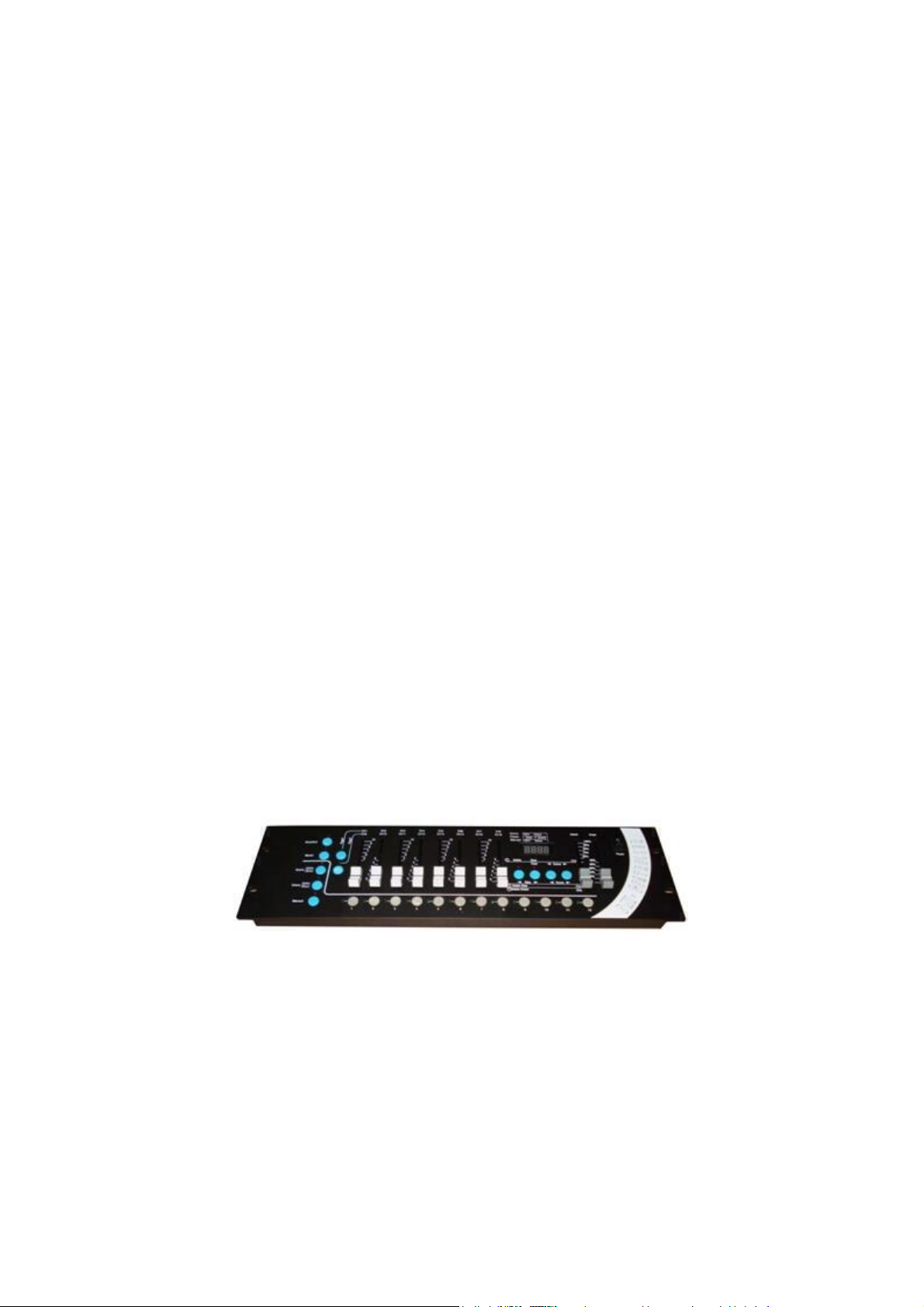
LIGHT4ME DMX 192 V2
Instrukcja obsługi / User Manual
LIGHT4ME
DMX 192 V2
Instrukcja obsługi / User Manual
Page 2

LIGHT4ME DMX 192 v2
Instrukcja obsługi / User Manual
1
POLSKI
Spis treści
Bezpieczeństwo użytkowania .................................................................................................... 2
Konserwacja .............................................................................................................................. 2
Specyfikacja techniczna ............................................................................................................ 3
Informacje dotyczące bezpieczeństwa ...................................................................................... 3
Montaż sterownika ..................................................................................................................... 3
Podłączanie się do sterownika ................................................................................................... 4
Adresowanie DMX512 ............................................................................................................... 4
Wyświetlanie cyfr ................................................................ ....................................................... 4
Panel tylni .................................................................................................................................. 5
Panel przedni ................................ ................................ ................................ ............................. 6
Przyciski liczb (1-12) w trybie scen / chase / ręcznego sterowania ............................................ 6
Edycja scen ............................................................................................................................... 8
Edycja chase ............................................................................................................................. 9
Uruchamianie sceny ................................................................................................................ 10
Uruchamianie chase ................................................................................................................ 10
Sterowanie ręczne ................................ ................................ ................................................... 11
Operacja kopiowania danych sterownika ................................................................................. 11
Informacja o zużytym sprzęcie elektrycznym i elektronicznym ................................................ 13
Page 3
LIGHT4ME DMX 192 v2
Instrukcja obsługi / User Manual
2
Bezpieczeństwo użytkowania
Przed użyciem prosimy o szczegółowe zapoznanie się z instrukcją obsługi. Prosimy również o zacho-
wanie jej na przyszłość. Instrukcja zawiera zasady bezpiecznego korzystania z urządzenia.
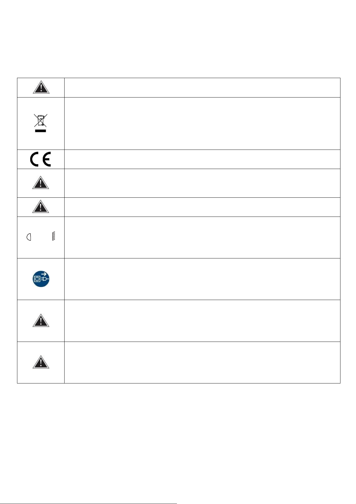
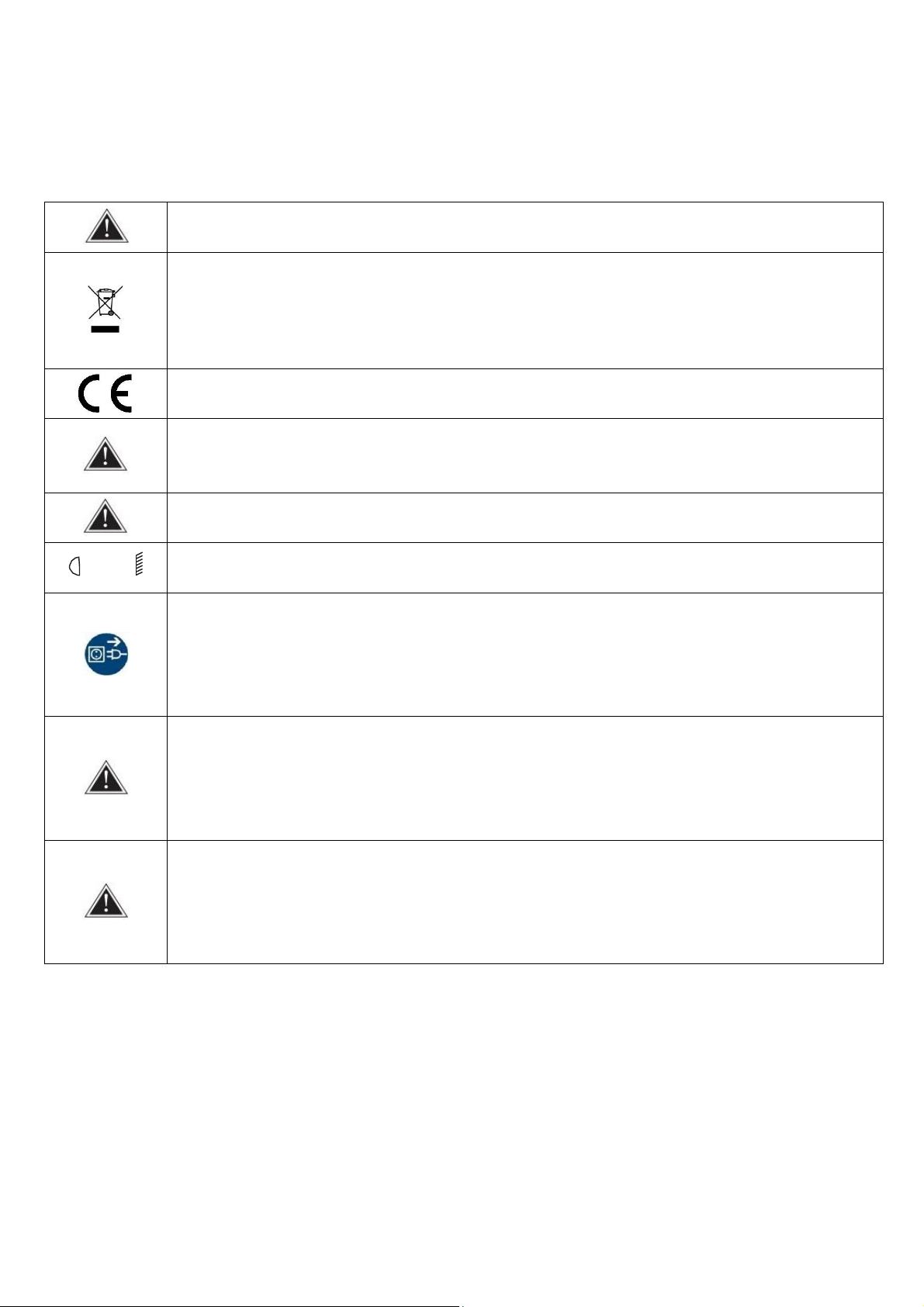
UWAGA! URZĄDZENIA NIE WOLNO WYRZUCAĆ DO ODPADÓW DOMOWYCH.
To oznaczenie oznacza, że produkt nie może być wyrzucany razem z odpadami domowymi w całej
UE. W celu zapobiegnięcia potencjalnym szkodom dla środowiska lub zdrowia, zużyty produkt należy
poddać recyklingowi. Zgodnie z obowiązującym prawem, nie nadający się do użycia sprzęt elek-
tryczny i elektroniczny należy zbierać osobno, w specjalnie do tego celu wyznaczonych punktach
zbierania zużytego sprzętu, celem ich przetworzenia i ponownego wykorzystania na podstawie obo-
wiązujących norm ochrony środowiska.
Produkt opisany w tej instrukcji jest zgodny z dyrektywami europejskimi, dlatego jest oznaczony zna-
kiem CE.
Urządzenie należy trzymać z dala od dzieci i niewykwalifikowanych osób. Producent nie ponosi
odpowiedzialności za szkody spowodowane nieprawidłowym użytkowaniem.
Przed użyciem upewnij się, że obudowa nie jest uszkodzona.
‐‐1 m
Zapewnij minimum 1 m dystansu pomiędzy urządzeniem a materiałami łatwopalnymi.
Urządzenie pracuje na zasilaniu oznaczonym na obudowie – nie należy podłączać do prądu o innych
parametrach. Zadbaj, aby urządzenie i źródło zasilania było uziemione. Odłącz urządzenie z zasilania
przed zdjęciem obudowy lub konserwacją. Jeżeli podczas pracy urządzenia pojawią się zakłócenia,
natychmiast odłącz przewód zasilający od źródła zasilania!
Urządzenie do użytku zewnętrznego i wewnętrznego, nie narażać na długotrwałe działanie wilgoci.
Nie należy narażać produktu na bezpośrednie działanie słońca lub innych urządzeń oświetleniowych.
Nie należy instalować urządzenia na podłożu narażonym na wibracje. Optymalna temperatura oto-
czenia pracy urządzenia to -15°C – 40°C. Nie użytkuj urządzenia przez czas dłuższy niż 10 godzin!
Konserwacja
1. Urządzenie może użytkować tylko wykwalifikowany personel, szkody spowodowane użytkowaniem
niezgodnym z przeznaczeniem lub próbą samodzielnej naprawy nie podlegają gwarancji. Wewnątrz
opakowania nie ma żadnych części serwisowych, naprawy mogą być wykonywane wyłącznie przez
autoryzowany punkt serwisowy.
2. Regularne czyszczenie umożliwia długotrwałe użytkowanie.
Page 4

LIGHT4ME DMX 192 v2
Instrukcja obsługi / User Manual
3
Specyfikacja techniczna
Parametr
Wartość
Sygnał wyjściowy
DMX512
Kanały DMX
1-192
Ilość kanałów kontroli na urządzenie
16
Ilość skanerów na urządzenie
12
Ilość chase
12
Ilość kroków w chase
100
Ilość scen
100
Ilość odtwarzanych scen
12
Sterowanie ręczne
Tak
Sterowanie dźwiękiem
Tak
Funkcja blackout
Tak
Możliwość dopasowania czasu trwania chase
Tak
Regulacja czasu przejścia między kolejnymi chase
Tak
Port wyjścia DMX
XLR-D3F
Zasilanie
AC90-240V, 50-60Hz
Moc
4W
Wymiary
53.5 x 18.5 x 10 cm
Waga
2.5 kg
Informacje dotyczące bezpieczeństwa
Sterownik musi być uziemiony, aby zapewnić bezpieczeństwo użytkownika.
Gdy sterownik jest włączony, nie należy podłączać ani odłączać kabla DMX512, aby uniknąć znisz-
czenia elementów elektronicznych portu w sterowniku.
Nie zalewaj sterownika żadną cieczą, aby uniknąć zniszczenia elementów elektrycznych i funkcji
sterownika.
Sterownik to precyzyjny sprzęt elektroniczny. Zwróć uwagę na ochronę przed wilgocią i kurzem.
Czyść regularnie panel sterownika.
Montaż sterownika
Zawartość opakowania:
Sterownik: 1
Kabel zasilający: 1
Instrukcja obsługi: 1.
Struktura instalacyjna kontrolera jest zgodna z międzynarodowym standardem „19” 3U. Można go osadzić w płycie do obsługi lub umieścić bezpośrednio na stole lub 19-calowym case.
Sterownik ma stałe napięcie wyjściowe w szerokim zakresie napięć zasilania, które pasuje do stan-
dardów całego świata. Przed podłączeniem zasilania należy sprawdzić, czy napięcie mieści się w normalnym zakresie urządzenia.
W przypadku konieczności wymiany bezpiecznika, należy zastosować bezpiecznik o wydajności prą-
dowej oznaczonej z tyłu urządzenia.
Page 5
LIGHT4ME DMX 192 v2
Instrukcja obsługi / User Manual
4
Podłączanie się do sterownika
Zgodnie z protokołem DMX512, kabel sygnałowy DMX musi być kablem ekranowanym o impedancji
120Ω. W praktyce, jeśli kabel jest zbyt krótki, można go zastąpić wysokiej jakości ekranowanym, dwu-
żyłowym kablem mikrofonowym.
Użytkownik podłącza każdy koniec kabla do wtyczki XLR. Pin 1 wtyczki XLR jest podłączony do siatki
ekranującej kabla. Skręcone linie (różniące się kolorami) są podłączone do pinów 2 i 3. Pin 3 to sygnał
+, a pin 2 to sygnał -. Pinów 2 i 3 nie można pomylić.
Aby zapewnić poprawną transmisję sygnału DMX, do ostatniego urządzenia należy podłączyć terminator DMX o parametrze 120Ω. Operacja ta jest następująca: podłącz rezystor 120Ω do pinów 2 i 3, a
następnie podłącz ją do wyjścia ostatniego urządzenia.
Adresowanie DMX512
Sterownik wykorzystuje kanały 1-192 DMX512 do przesyłania sygnałów sterujących do różnych urządzeń. Każde urządzenie jest wyposażone w 16 kanałów sterujących.
Nr urządzenia
Pierwszy adres DMX urządzenia
Kod dziesiętny
Bit adresu urządzenia
1
1
100000000
2
17
100010000
3
33
100001000
4
49
100011000
5
65
100000100
6
81
100010100
7
97
100001100
8
113
100011100
9
129
100000010
10
145
100010010
11
161
100001010
12
177
100011010
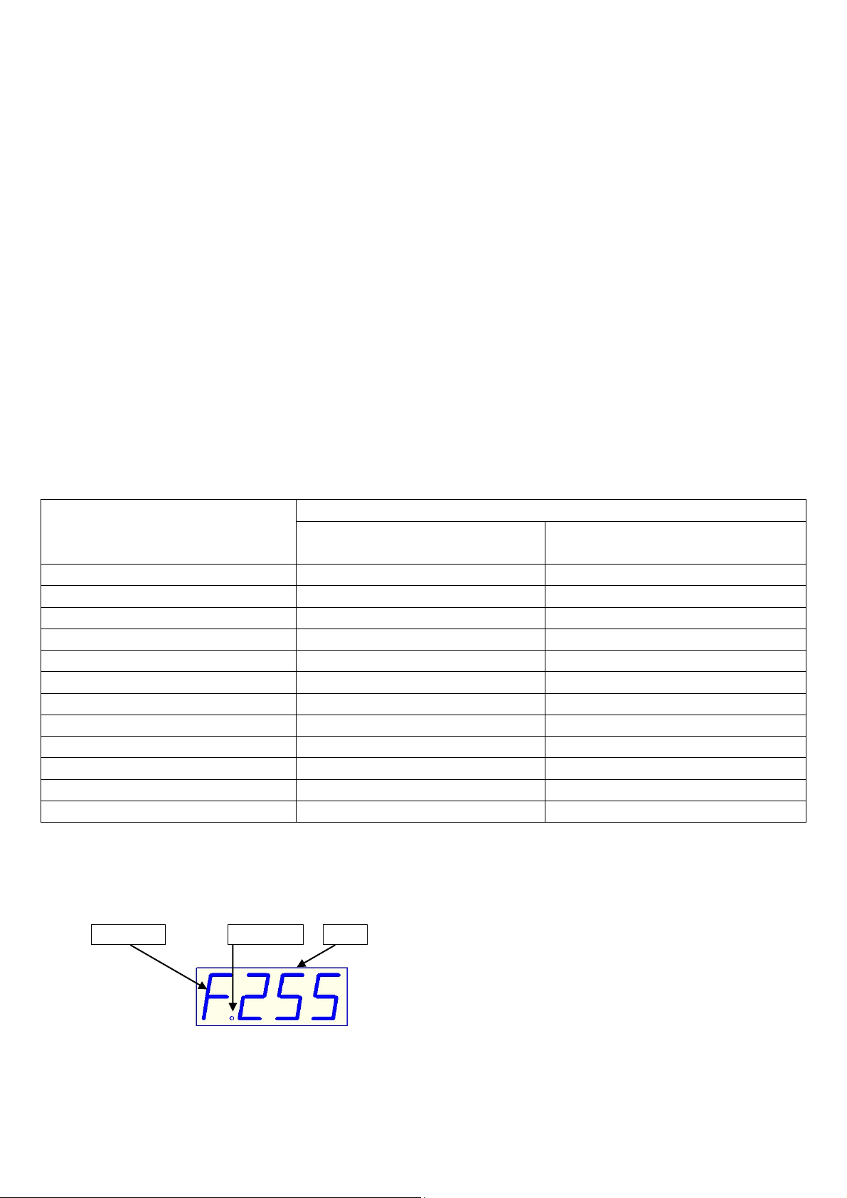
Wyświetlanie cyfr
1. Uruchamianie sceny i sterowanie ręczne:
Nr kanału Separator Kanał
Nr kanału – wyświetla kanał aktualnego suwaka z zakresu 0-f przypisanego do kanału z zakresu
1-16.
Kanał – wyświetla aktualną wartość kanału wejściowego (zakres: 000-255).
Page 6
LIGHT4ME DMX 192 v2
Instrukcja obsługi / User Manual
5
Separator – służy do odróżniania zawartości wyświetlacza.
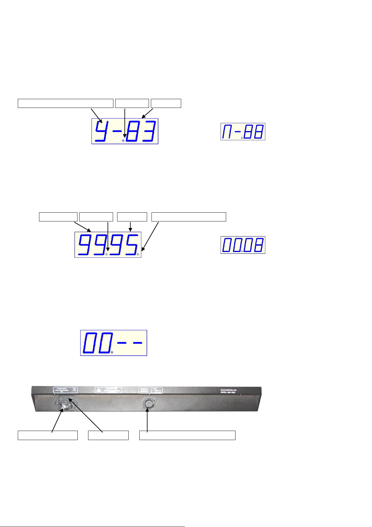
2. Edytowanie sceny:
Oznaczenie sceny w efekcie Separator Nr sceny
(wyświetla scenę w efekcie) (nie wyświetla efektu)
1. Oznaczenie sceny w efekcie – wybór sceny (Y oznacza “Tak”, N oznacza „Nie”)
2. Nr sceny – wyświetla edytowaną scenę (zakres: 00-99).
3. Separator – służy do odróżniania zawartości wyświetlacza.
3. Edytowanie i uruchamianie przechodzenia między chase:
Krok chase Separator Nr sceny Krok ostatniego chase
(wyświetla ostatni krok) (wyświetla krok, który nie jest ostatni)
1. Krok chase – nr edytowanego kroku chase, zakres: 00-99.
2. Nr sceny – scena zapisze się w danym kroku chase, zakres: 00-99.
3. Krok ostatniego chase – krok, który w danym chase jest ostatni.
4. Separator – służy do odróżniania zawartości wyświetlacza.
5. Brak chase – brak zawartości w chase (jak poniżej).
(wyświetla brak chase)
Panel tylni
Gniazdo zasilania Bezpiecznik Port wyjściowy sygnału DMX
Page 7
LIGHT4ME DMX 192 v2
Instrukcja obsługi / User Manual
6
Panel przedni
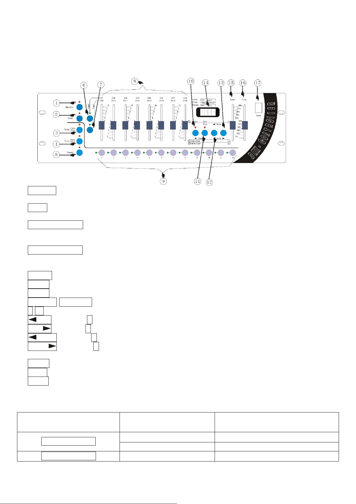
1) Blackout – wciśnięcie przycisku sprawia, że światła zaświecają się. Jeśli wartość wyjściowa na
wszystkich kanałach jest równa 0, rezultatem jest brak światła.
2) Music – sterowanie dźwiękiem. Wciśnięcie przycisku sprawia, że światła zaświecają się. Urucho-
mienie programu odbywa się za pomocą wbudowanego mikrofonu.
3) Scene Edit / Run – Jeśli czas wciśnięcia jest dłuższy od 1 s, kontrolka wskazuje tryb edycji scen.
Ponowne wciśnięcie przez czas dłuższy niż 1 s sprawia, że tryb przełącza się z edycji na urucho-
mienie scen. Światła zawsze są zaświecone.
4) Chase Edit / Run – Jeśli czas wciśnięcia jest dłuższy od 1 s, kontrolka wskazuje tryb edycji chase.
Ponowne wciśnięcie przez czas dłuższy niż 1 s sprawia, że tryb przełącza się z edycji na urucho-
mienie chase. Światła zawsze są zaświecone.
5) Manual – sterowanie ręczne.
6) Page1 – Przyciski dostępu – strona 1.
7) Page2 – Przyciski dostępu – strona 2.
8) Ch1/Ch9-Ch8/Ch16 – Kanał suwaka (strona 1: 1-8 / strona 2: 9-16).
9) 1-12 – przyciski numeryczne 1-12. Służy do wybierania numeru urządzenia.
10) Step – przycisk A, przechodzenie do poprzedniego kroku, usuwanie sceny.
11) Step - przycisk B, wykonanie kopii sceny, zapis sceny, przechodzenie do następnego kroku.
12) Scene - przycisk C, przechodzenie do poprzedniej sceny.
13) Scene - przycisk D przechodzenie do następnej sceny.
14) Wyświetlacz cyfrowy.
15) Speed - fader modyfikacji prędkości.
16) Cross - fader stopniowej modyfikacji.
17) Power - przełącznik zasilania.
Przyciski liczb (1-12) w trybie scen / chase / ręcznego sterowania
Przycisk
Funkcja
Przyciski liczb 1-12
Scene Edit / Run
Edycja sceny
Wybór lampy
Uruchamianie sceny
Wybór uruchamianych scen
Chase Edit / Run
Edycja chase
Wybór edytowanych chase
Page 8
LIGHT4ME DMX 192 v2
Instrukcja obsługi / User Manual
7
Uruchamianie chase
Wybór uruchamianych chase
Manual
Sterowanie ręczne
Wybór lampy
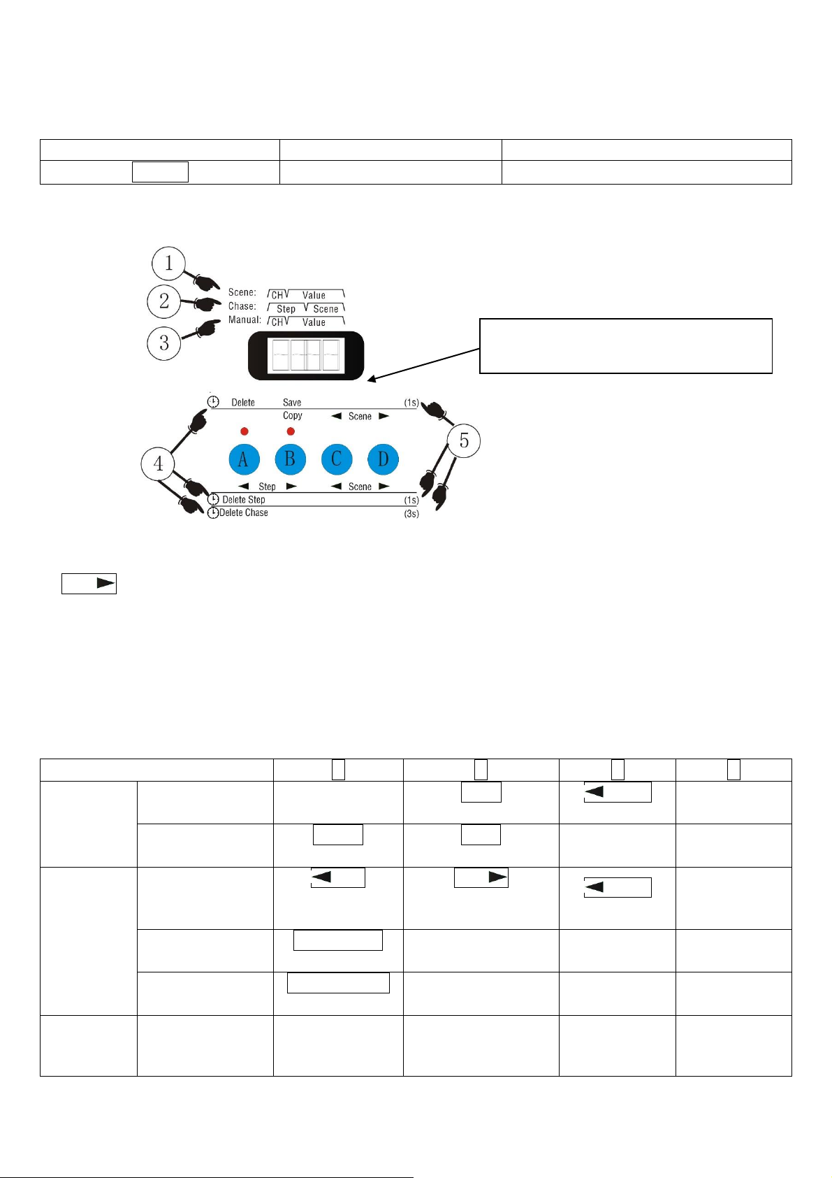
Opis przycisków funkcyjnych A, B, C, D
① Step Podczas uruchamiania sceny na wyświetlaczu pokazuje się numer CH sceny oraz jego
wartość (value).
② Podczas uruchamiania chase na wyświetlaczu pokazuje się wartość step oraz numer sceny.
③ Podczas sterowania ręcznego na wyświetlaczu pokazuje sie, numer CH oraz jego wartość (value).
④ Ikona opóźnienia (delay).
⑤ Wybór wartości opóźnienia.
A, B, C, D – cztery sceny w edycji
Przycisk/funkcja
A B C
D
Edycja
sceny
Brak opóźnienia
--
Copy
Kopiowanie sceny
Scene
Wybór sceny
Edycja sceny
Opóźnienie 1 s
Delete
Usuń scenę
Save
Zapis sceny
--
--
Edycja
chase
Brak opóźnienia
Step
Wybór kroku
wstecz
Step
Wybór kroku do
przodu
Scene
Wybór sceny
Edycja chase
Opóźnienie 1 s
Delete Step
Usuń krok
--
--
--
Opóźnienie 3 s
Delete Chase
Usuń chase
--
--
--
Ręczne
sterowa-
nie
Brak opóźnienia
Wyczyszczenie
stanu
urządzenia
--
--
Sterowanie
ręczne
A, B, C, D – przyciski funkcyjne do
edycji scen
Page 9
LIGHT4ME DMX 192 v2
Instrukcja obsługi / User Manual
8
Edycja scen
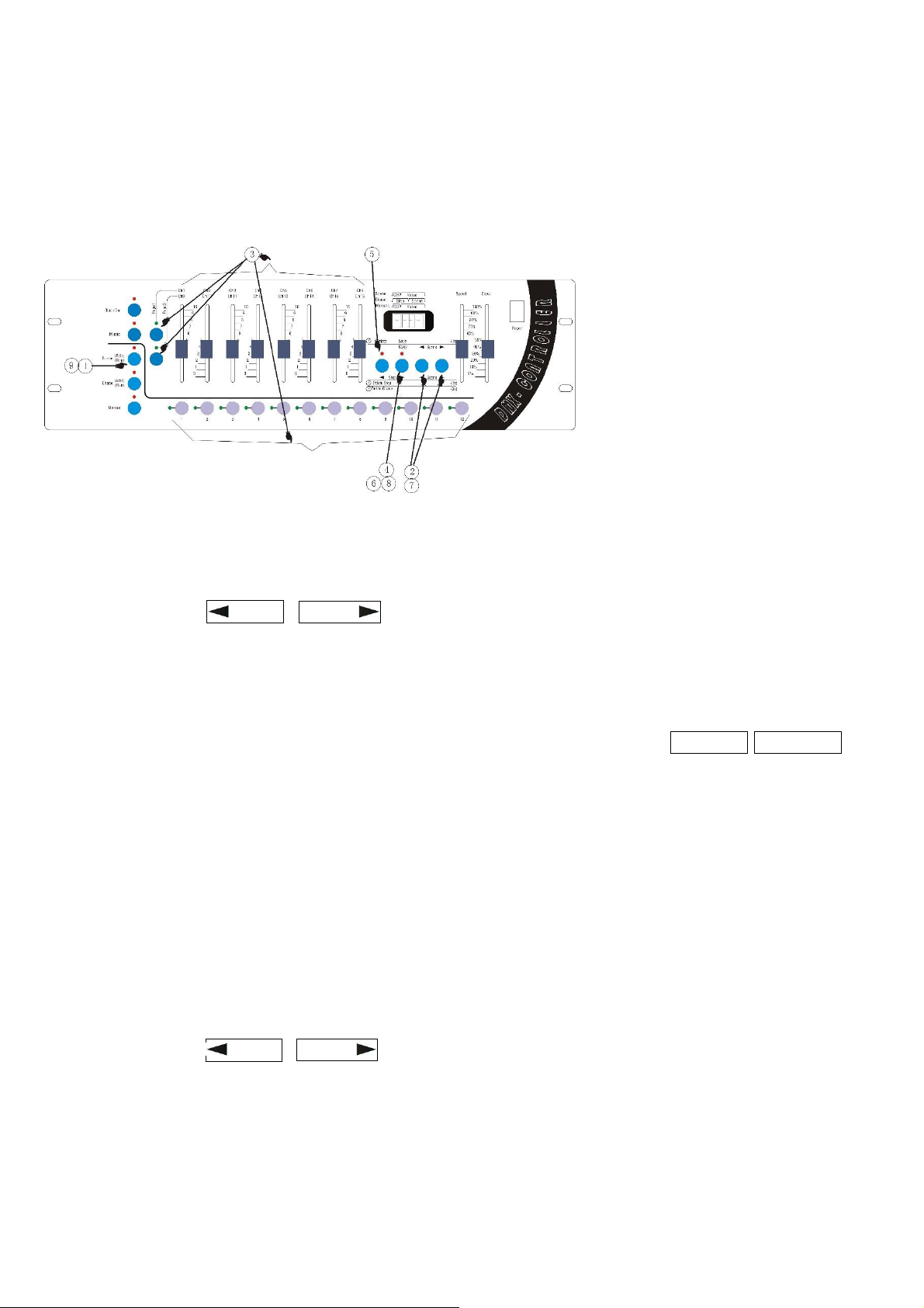
Panel edycji scen:
Kolejne kroki edycji sceny:
① Wciśnij przycisk SCENE przez czas dłuższy niż 2 s. Kontrolka zacznie migać. Wejdź do trybu edycji
scen.
② Użyj przycisków Scene i Scene , aby wybrać numer sceny.
Jeśli chcesz edytować aktualną scenę, przejdź do punktu 3.
Jeśli chcesz usunąć aktualną scenę, przejdź do punktu 5.
Jeśli chcesz skopiować aktualną scenę, przejdź do punktu 7.
③ Edycja aktualnej sceny: użyj przycisków liczb 1-12, aby wybrać numer światła. Następnie przy
pomocy przycisków Page1 i Page2, wybierz wartość każdego kanału z listy Ch1/Ch9-Ch8/Ch16.
④ Zapis edytowanej sceny: wciśnij przycisk SAVE przez czas dłuższy niż 2 s. Jeśli kontrolka zaświeci
się, a ekran zamiga, aktualnie edytowana scena została zapisana.
Jeśli chcesz kontynuować edycję scen, przejdź do kroku 2 i wybierz inną scenę do edycji.
Jeśli chcesz wyjść z trybu edycji scen, przejdź do kroku 9.
⑤ Usunięcie aktualnej sceny: wciśnij przycisk DELETE przez czas dłuższy niż 2 s. Jeśli kontrolka
zaświeci się, aktualna scena została usunięta.
Jeśli chcesz kontynuować edycję scen, przejdź do kroku 2 i wybierz inną scenę do edycji.
Jeśli chcesz wyjść z trybu edycji scen, przejdź do kroku 9.
⑥ Kopiowanie aktualnej sceny: wciśnij przycisk COPY aż kontrolka zaświeci się. Wejdź do trybu
kopiowania. Zawartość aktualnej sceny będzie źródłem, na którym operacje kopiowania będą miały
miejsce.
⑦ Użyj przycisków Scene i Scene , aby wybrać numer sceny, który zawiera zawartość sceny do
skopiowania.
⑧ Wciśnij przycisk COPY ponownie. Kontrolka przestanie świecić. Proces kopiowania zakończył się,
zawartość sceny źródłowej została zapisana w scenie docelowej.
Jeśli chcesz kontynuować edycję innej sceny, przejdź do kroku 2 i wybierz inną scenę do edycji.
Jeśli chcesz wyjść z trybu edycji scen, przejdź do kroku 9.
Page 10
LIGHT4ME DMX 192 v2
Instrukcja obsługi / User Manual
9
⑨ Wyjście z trybu edycji scen: wciśnij przycisk SCENE przez czas dłuższy niż 2 s. Kontrolka zacznie
migać i zaświeci się. System zamknie tryb edycji scen.
Edycja chase
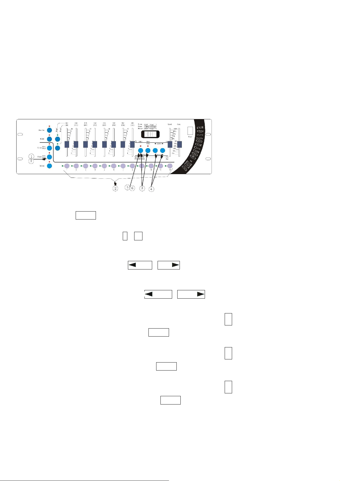
Panel edycji chase:
Kolejne kroki edycji chase:
① Wciśnij przycisk Chase przez czas dłuższy niż 2 s, a kontrolka zaświeci się, co oznacza, że chase
jest w trybie edycji (wyświetlacz pokaże “CHA”, żądając wyboru numeru chase).
② Wybierz numer: użyj przycisków 1 – 12 (jeśli program jest pusty, wyświetlacz pokazuje “00.—“. Jeśli
krok wynosi 0, wyświetlony zostanie numer zapisanej sceny, np. “00.08”.
Jeśli chcesz usunąć aktualny chase, przejdź do kroku 5.
③ Wybierz krok programu: przyciski Step i Step służą do wyboru kroku program, który chcesz
edytować.
Jeśli chcesz usunąć aktualny chase, przejdź do kroku 6.
④ Wybierz numer sceny: użyj przycisków Scene i Scene . Zostanie on zapisany kroku chase
wybranym w punkcie ③.
Jeśli chcesz edytować inne kroki aktualnego chase, powtarzaj punkt ③.
⑤ Usuń aktualny program: wciśnij przycisk Delete przez czas dłuższy niż 3 s, a kontrolka zamiga
2 razy, wtedy aktualny chase zostanie usunięty (wyświetlacz pokaże ”00.--”).
Jeśli chcesz edytować inne kroki aktualnego chase, powtarzaj punkt ③.
⑥ Usuń aktualny krok chase: wciśnij przycisk Delete przez czas dłuższy niż 1 s, a kontrolka zaświeci
się 1 raz, wtedy aktualny krok zostanie usunięty.
Jeśli chcesz edytować inne kroki aktualnego chase, powtarzaj punkt ③.
⑦ Wyjście z trybu edycji chase: wciśnij przycisk Chase przez czas dłuższy niż 1 s, a kontrolka zaświeci
w sposób ciągły po migotaniu, wtedy tryb zostanie zmieniony na tryb uruchomienia chase.
Page 11
LIGHT4ME DMX 192 v2
Instrukcja obsługi / User Manual
10
Uruchamianie sceny
Panel uruchamiania sceny:
Kolejne kroki uruchamiania sceny:
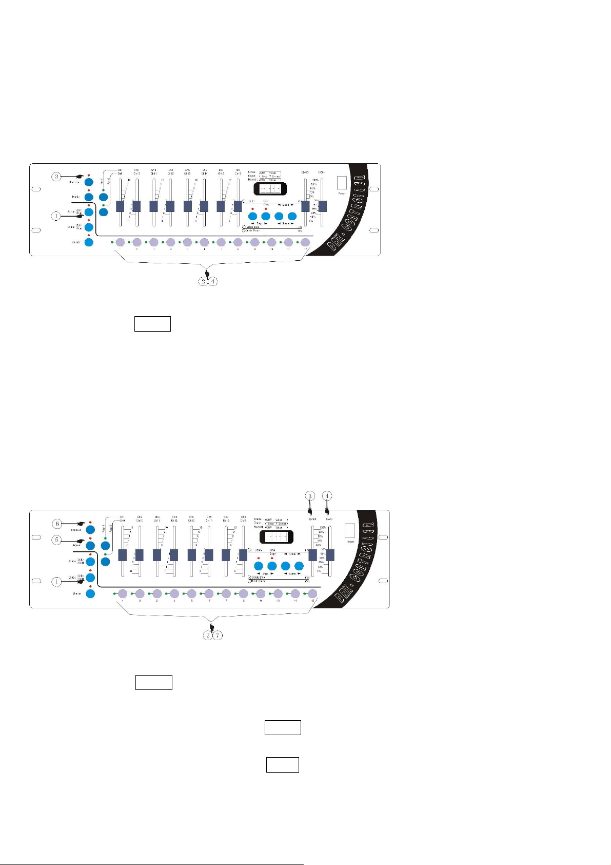
① Wciśnij przycisk Scene, a światła będą ciągle włączone, co oznacza wejście do trybu uruchamiania
sceny.
② Wybierz numer sceny: użyj przycisków 1-12.
③ Jeśli chcesz, by wszystkie światła były wyłączone, wciśnij przycisk Blackout. Jeśli kontrolka świeci
się, efekt ten został włączony.
④ Zamknięcie efektów sceny: użyj przycisków 1-12, by wybrać numer sceny, którą chcesz zamknąć.
Uruchamianie chase
Panel uruchamiania chase:
Kolejne kroki uruchamiania chase
① Wciśnij przycisk Chase, a kontrolka zaświeci się.
② Wybierz numer chase: użyj przycisków 1-12.
③ Dostosuj czas ustawienia: ustaw suwak Speed tak, by dostosować czas ustawienia kroków chase.
Górny zakres oznacza najkrótszy czas, a dolny zakres oznacza najdłuższy czas.
④ Dostosuj czas zacienienia: ustaw suwak Cross tak, by dostosować czas zacienienia kroków chase.
Górny zakres oznacza brak zacienienia, a dolny zakres oznacza najdłuższy czas zacienienia.
Page 12
LIGHT4ME DMX 192 v2
Instrukcja obsługi / User Manual
11
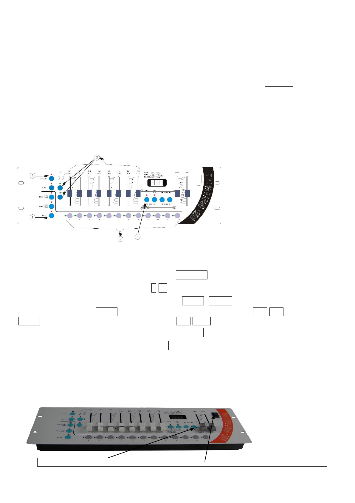
⑤ Tryb aktywacji dźwiękiem: jeśli chcesz aktywować chase w trybie aktywacji dźwiękiem, wciśnij przycisk Music, by włączyć światło. Jeśli światło jest wyłączone, oznacza to, że tryb aktywacji dźwiękiem
jest wyłączony.
⑥ Scena bez świateł: jeśli chcesz, by światła były wyłączone, wciśnij przycisk Blackout.
⑦ Wyjście z uruchamiania chase: użyj przycisków 1-12, by wybrać numer uruchamianej sceny, która
zostanie wyłączona.
Sterowanie ręczne
Panel sterowania ręcznego:
Kolejne kroki sterowania ręcznego:
① Wejście do trybu manualnego: wciśnij przycisk MANUAL, a kontrolka zaświeci się.
② Ręczny wybór świateł: użyj przycisków 1-12.
③ Zmiana numeru kanału: przy pomocy przycisków Page1 i Page2 możesz wybrać światła w sposób
ręczny. Wciśnij przycisk Page1, kontrolka zaświeci się, zakres kanałów to Ch1-Ch8. Wciśnij przycisk
Page2, kontrolka zaświeci się, zakres kanałów to Ch9-Ch16.
④ Usunięcie ustawień ręcznych: wciśnij przycisk DELETE, by usunąć efekty ustawień ręcznych.
⑤ Efekt blackout: wciśnij przycisk BLACKOUT.
Operacja kopiowania danych sterownika
Operacja wyprowadzania sekwencji
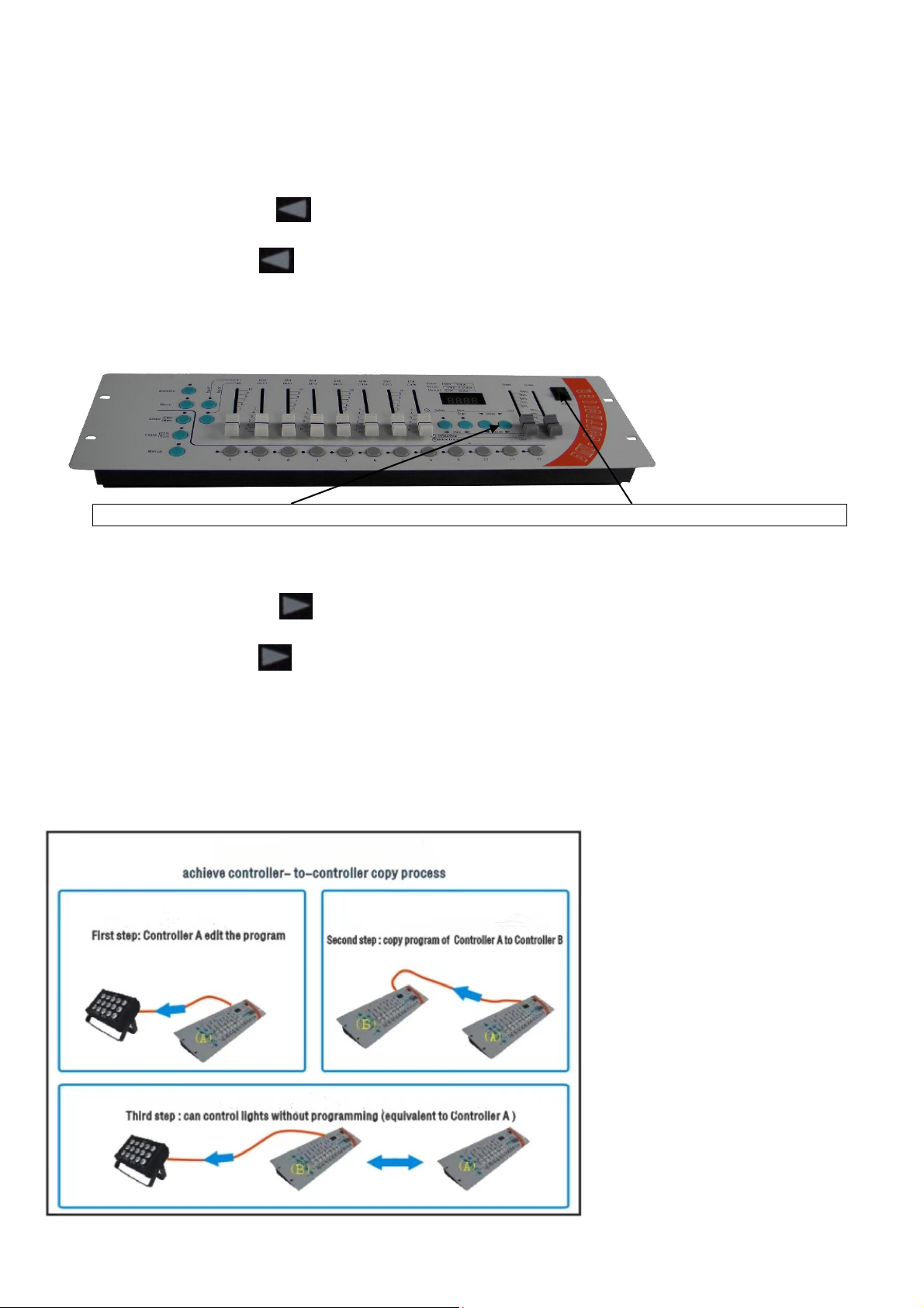
1. Wciskaj przycisk, zanim otworzysz przełącznik zasilania. 2. Otwórz przełącznik zasilania.
Page 13
LIGHT4ME DMX 192 v2
Instrukcja obsługi / User Manual
12
1. Połącz „kontroler wyjścia sekwencji” z „kontrolerem wejścia sekwencji” za pomocą specjalnego ka-
bla do kopiowania danych i podłącz oba kontrolery do zasilania.
2. Naciskaj przycisk sceny “ ” na “kontrolerze wyjścia sekwencji”, a następnie otwórz przełącznik
zasilania. Urządzenie przejdzie do “stanu wyjściowego” po tym, jak na wyświetlaczu pojawi się „SE.xx”,
wtedy przestań naciskać “ ”.
Operacja wprowadzania sekwencji
1. Wciskaj przycisk, zanim otworzysz przełącznik zasilania. 2. Otwórz przełącznik zasilania.
1. Połącz „kontroler wyjścia sekwencji” z „kontrolerem wejścia sekwencji” za pomocą specjalnego ka-
bla do kopiowania danych i podłącz oba kontrolery do zasilania.
2. Naciskaj przycisk sceny “ ”na “kontrolerze wyjścia sekwencji”, a następnie otwórz przełącznik
zasilania. Urządzenie przejdzie do “stanu wyjściowego” po tym, jak na wyświetlaczu pojawi się „SE.xx”,
wtedy przestań naciskać “ ”.
3. Teraz rozpoczyna się proces kopiowania, a wyświetlacz “kontrolera wejścia sekwencji” pokaże
wzrost 2 ostatnich cyfr. Gdy pojawi się komunikat “END”, kopiowanie jest zakończone. Wtedy możesz
zamknąć przełącznik zasilania i wyjąć kabel do kopiowania danych. Po ponownym uruchomieniu “kon-
trolera wejścia sekwencji”, Użytkownik może używać go do sterowania światłem.
Schemat blokowy operacji kopiowania danych
Page 14

LIGHT4ME DMX 192 v2
Instrukcja obsługi / User Manual
13
Informacja o zużytym sprzęcie elektrycznym i elektronicznym
Głównym celem regulacji europejskich oraz krajowych jest ograniczenie ilości odpadów powstałych
ze zużytego sprzętu elektrycznego i elektronicznego, zapewnienie odpowiedniego poziomu jego zbierania, odzysku i recyklingu oraz zwiększenie świadomości społecznej o jego szkodliwości dla środowiska naturalnego, na każdym etapie użytkowania sprzętu elektrycznego i elektronicznego. W związku
z powyższym należy wskazać, iż gospodarstwa domowe spełniają kluczową rolę w przyczynianiu się
do ponownego użycia i odzysku, w tym recyklingu zużytego sprzętu. Użytkownik sprzętu przeznaczonego dla gospodarstw domowych jest zobowiązany po jego zużyciu do oddania zbierającemu zużyty
sprzęt elektryczny i elektroniczny. Należy jednak pamiętać, aby produkty należące do grupy sprzętu
elektrycznego lub elektronicznego utylizowane były w uprawnionych do tego punktach zbiórki.
Page 15

LIGHT4ME DMX 192 v2
Instrukcja obsługi / User Manual
14
ENGLISH
Table of contents
Safety rules .............................................................................................................................. 15
Maintenance ............................................................................................................................ 15
Technical specification ............................................................................................................. 16
Cautions of safety ................................................................ ................................ .................... 16
Installation of controller ............................................................................................................ 16
Connecting to scanner ............................................................................................................. 17
Address distribution of DMX 512 ............................................................................................. 17
Digit display instruction ............................................................................................................ 17
Rear instruction ........................................................................................................................ 18
Panel instruction ...................................................................................................................... 19
The number keys (1-12) in the scene / procedures / manual control mode of the corresponding
menu ........................................................................................................................................ 20
Edit scene ................................................................................................................................ 21
Edit chase ................................................................................................................................ 22
Running scene ......................................................................................................................... 23
Running chase ......................................................................................................................... 24
Manual operation ................................................................................................ ..................... 24
The copy operation for the controller’s data ............................................................................. 25
The flow chart of the data copying operation ........................................................................... 26
Information about used electrical and electronic equipment .................................................... 26
Page 16
LIGHT4ME DMX 192 v2
Instrukcja obsługi / User Manual
15
Safety rules
Please read the user manual in detail before use. Please also keep it for future reference. The man-
ual contains rules for the safe use of the device.
WARNING! THE DEVICE MUST NOT BE DISPOSED OF WITH HOUSEHOLD WASTE. This symbol
indicates that this product must not be disposed of with household waste, according to the EU and
your national law. In order to prevent potential damage to the environment or health, the used product
must be recycled. In accordance with current legislation, unusable electrical and electronic devices
must be collected separately at the designated facilities for recycling, acting on the basis of applicable
environmental standards.
The product described in this manual comply with European directives and it is therefore CE marked.
Keep the device away from children and unqualified persons. The manufacturer is not liable for dam-
age caused by improper use.
Before use, make sure the housing is not damaged.
‐‐1 m
Ensure a minimum distance of 1 m between the device and flammable materials.
The device operates on the power supply marked on the housing – do not connect to a power supply
with different parameters. Ensure that the device and the power source are grounded. Disconnect
the device from the power supply before removing the housing or performing maintenance. If interfer-
ence occurs during operation, immediately disconnect the power cable from the power source!
The device for outdoor and indoor use, do not expose to prolonged moisture. Do not expose the prod-
uct to direct sunlight or other lighting devices.
Do not install the device on a surface subjected to vibration. The optimal ambient operating tempera-
ture of the device is -15°C - 40°C. Do not use the device for more than 10 hours!
Maintenance
1. The device may only be used by qualified personnel. Damage caused by improper use or attempted
repair is not covered by the warranty. There are no service parts inside the packaging. Repairs may
only be carried out by authorized service center.
2. Regular cleaning allows of long term use.
Page 17

LIGHT4ME DMX 192 v2
Instrukcja obsługi / User Manual
16
Technical specification
Parameter
Value
Output signal
DMX512
DMX channels
1-192
Maximum control channel amount of a scanner
16
Control amount of scanners
12
Amount of chase
12
Maximum chase steps in a chase
100
Amount of scanner scene
100
Running scene directly
12
Manual operation of scanner
Yes
Music run
Yes
Blackout function
Yes
Time of running chase can be adjusted
Yes
Cross of running chase can be adjusted
Yes
Port of DMX output
XLR-D3F
Power supply
AC90-240V, 50-60Hz
Power
4W
Size
53.5 x 18.5 x 10 cm
Weight
2.5 kg
Cautions of safety
Controller must be connected to the earth ground to ensure the safety of user.
When controller is working, do not plug in or plug out DMX512 cable to avoid destroying the elec-
tronic components of the port in the controller.
Do not splash any liquid to the controller to avoid destroying the electric components and the func-
tions of the controller.
The scanner controller is precise electronic equipment. Please pay attention to moisture proof pro-
tection and dustproof. And please clean the controller panel thermally.
Installation of controller
Contents in the package of scanner controller:
Scanner controller: 1
Power supply line: 1
User manual: 1.
Installing structure of scanner controller follows the international standard “19” 3U. It can be embedded
in operation board or directly installed in 19’’ shelf or cabinet.
The power of the controller has steady voltage output in a wide range of power supply voltage that it
is adopt to the power supply of all the world. Before the power supply is connected, please check
whether the voltage is in normal range of the device.
When the fuse needs to be replaced, please use the fuse with the current capacity signed on the rear
of the device.
Page 18
LIGHT4ME DMX 192 v2
Instrukcja obsługi / User Manual
17
Connecting to scanner
According to DMX512 protocol, DMX signal cable must be screened twist cable with impedance of
120Ω. In practical engineering installation, if the whole length of the cable is short, the cable may be
replaced by high quality screened two-core microphone cable.
User joins each end of the cable to a XLR plug. Foot 1 of the XLR plug is connected to the screen net
of the cable. Twist lines (distinguished by different colors) are connected to foot 2 and 3. Foot 3 is
signal + and foot 2 is signal -. Foot 2 and foot 3 of the plug cannot be confused.
To ensure correct DMX signal transmission, a 120Ω terminal matching resistance must be connected
to the last equipment to absorb terminal signal reflection. The operation is as following: connect a
120Ω resistance to foot 2 and foot 3 of a plug, then plug it to the output of the last scanner (or other
equipment).
Address distribution of DMX 512
Scanner controller utilizes channel 1-192 of DMX512 to transmit the control signals to various scanners. Each scanner is fixed with 16 control channels.
Scanner NO
First DMX address of scanner
Decimal code
Switch bit of scanner address
1
1
100000000
2
17
100010000
3
33
100001000
4
49
100011000
5
65
100000100
6
81
100010100
7
97
100001100
8
113
100011100
9
129
100000010
10
145
100010010
11
161
100001010
12
177
100011010
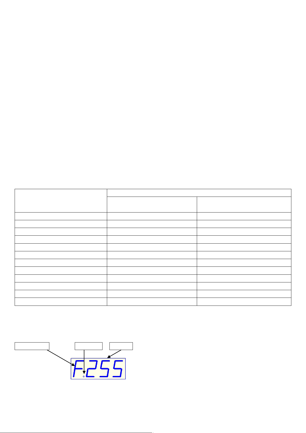
Digit display instruction
1. Running scene and manual operation display:
Channel NO Separator Channel
Channel NO – displays the channel of current fader 0-f corresponding to 1-16 channel.
Channel – displays the current input channel value (range: 000-255).
Page 19
LIGHT4ME DMX 192 v2
Instrukcja obsługi / User Manual
18
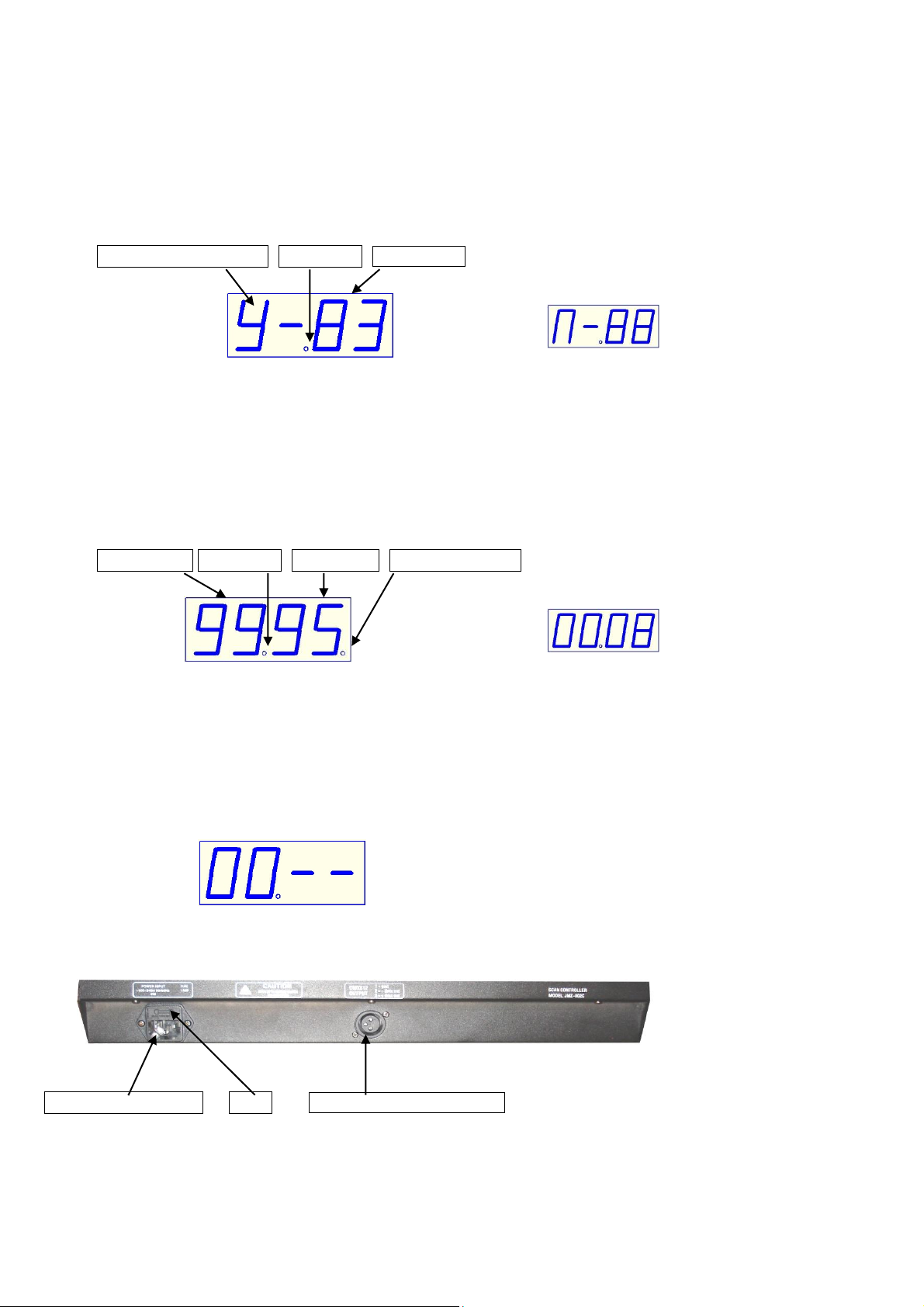
Separator – used in distinguishing different content.
2. Editing scene operation display:
Scene mark in effect Separator Scene NO
(displays scene in effect) (no effect display)
1. Scene mark in effect – the content of choosing the scene (Y means “Yes”, N means “NO”).
2. Scene NO – displays the editing scene (range: 00-99).
3. Separator – used in distinguishing different content.
3. Edit and running cross chase operation display:
Chase step Separator Scene NO Last chase step
(last step display) (not last step display)
1. Chase step – the editing chase step NO, range: 00-99.
2. Scene NO – the scene will save in the chase step, range: 00-99.
3. Last chase step – the step is the last chase step.
4. Separator – used in distinguishing different content.
5. No chase display – no content in the chase (as follows).
(no chase display)
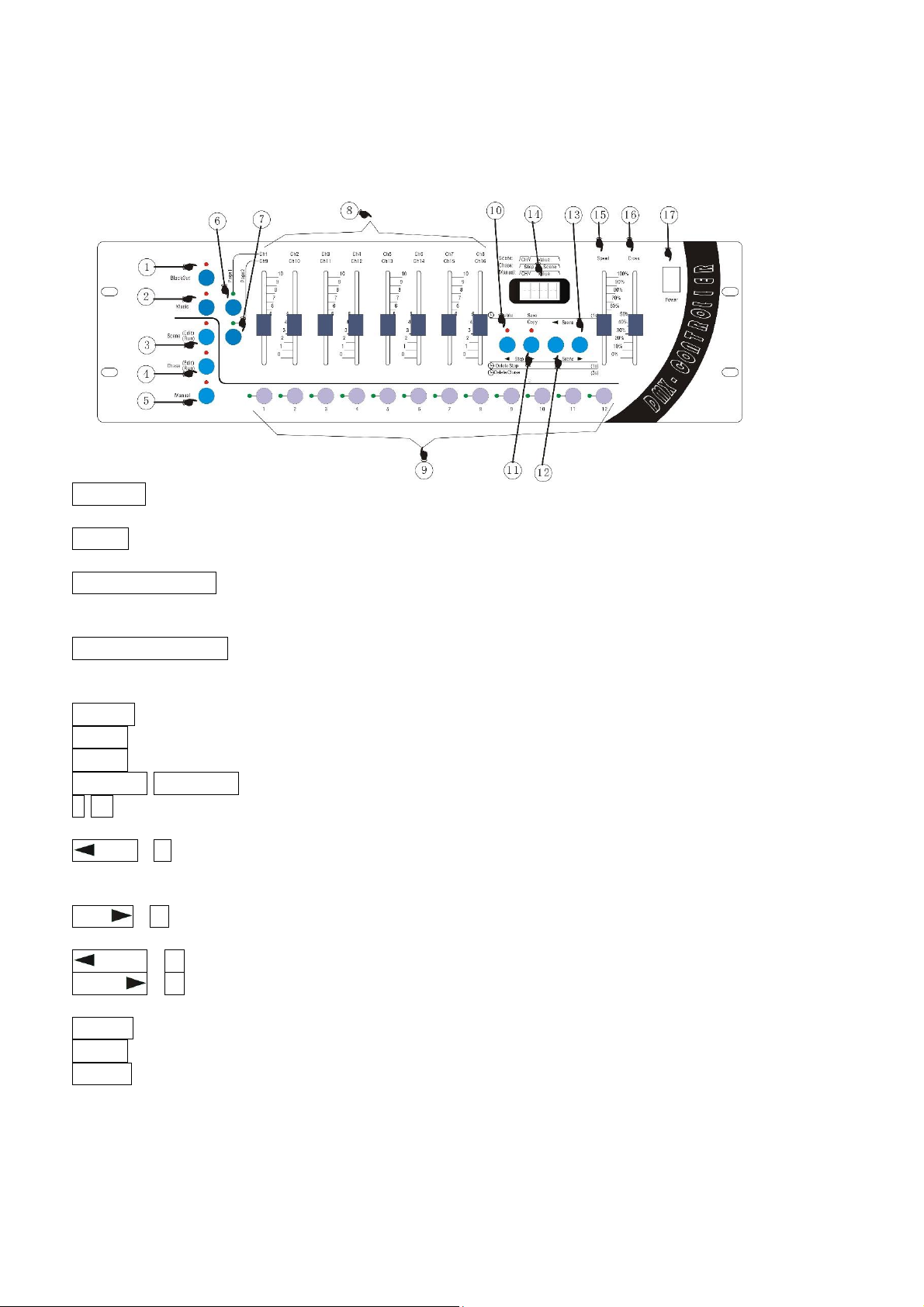
Rear instruction
Power input socket Fuse DMX signal output port
Page 20
LIGHT4ME DMX 192 v2
Instrukcja obsługi / User Manual
19
Panel instruction
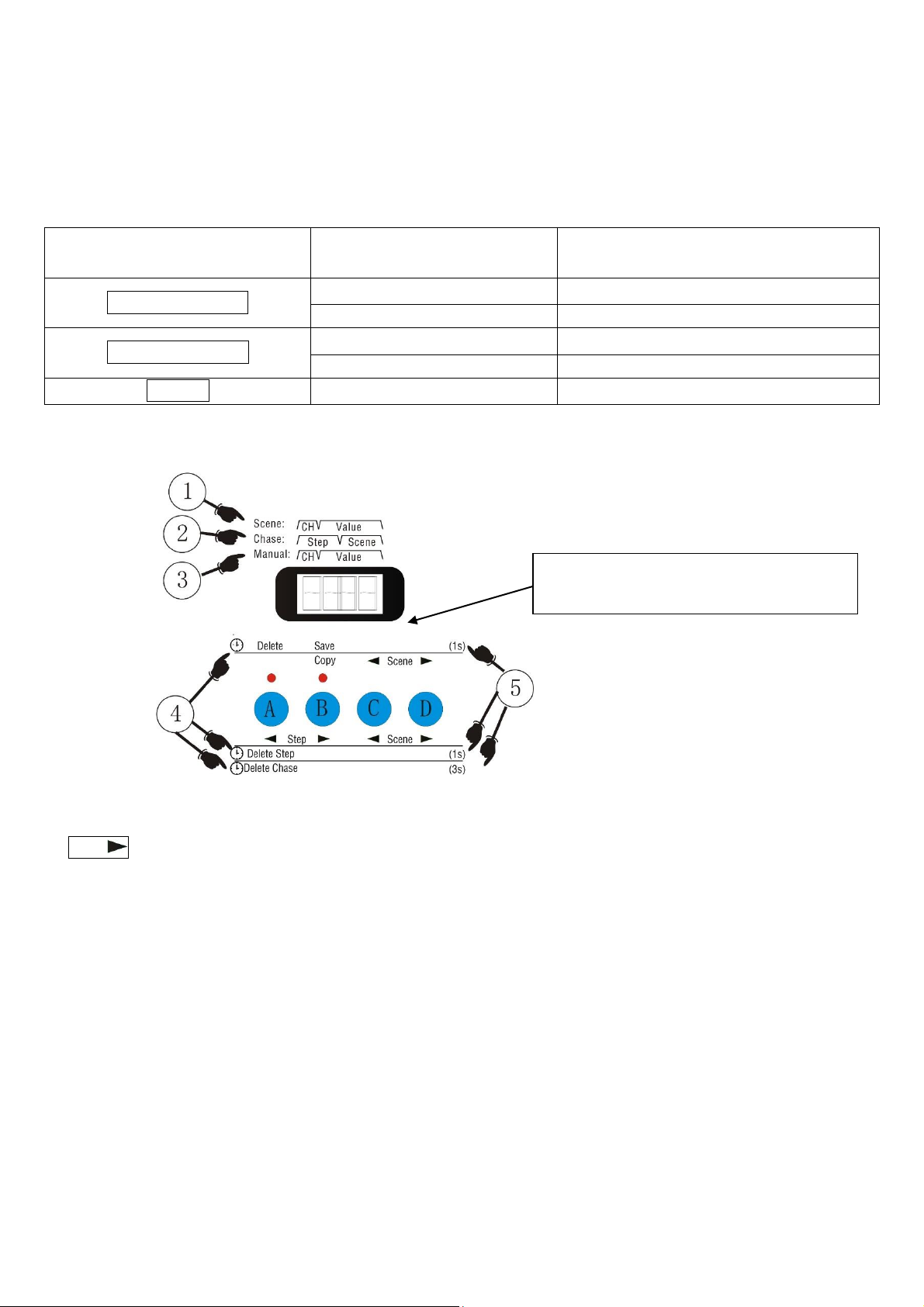
18) Blackout – Output black keys. Pressing the button makes light bright. When the control output value
of platform at all channels is 0, the result are black scenes.
19) Music - Voice-activated key. Pressing the button makes light bright. Running the program is trig-
gered by the built-in microphone.
20) Scene Edit / Run - Scene Editor / run key. When pressing time is more than 1 second, the indicator
light flashes into the scene editor state. When pressing for 1 second again, it withdraws from editing
the state to the running state. Bright light is always on.
21) Chase Edit / Run - Walking light program editor / run key. When pressing time is more than 1
second, the indicator light flashes into the scene editor state. When pressing for 1 second again, it
withdraws from editing the state to the running state. Bright light is always on.
22) Manual - Control key.
23) Page1 - Access keys page 1.
24) Page2 - Access keys page 2.
25) Ch1/Ch9-Ch8/Ch16 - Channel fader (page one 1-8 / page two 9-16).
26) 1-12 - The number keys 1-12. Used to select the No. field, and follow procedures and signal lights
to choose.
27) Step - A key (run). Operation to remove lantern; (edit scenes) deleted scenes; (Edit the walking
light procedure) Step Remove Programs / Remove Programs / decreasing step-by-step selection
procedure.
28) Step - B key (edit scenes). scene copy / preserve the scene; (Editor lights go procedure) incre-
mental step-by-step selection procedure.
29) Scene - C key (Scene Editor / walking lights Procedure). Its reduced choice key of scenes.
30) Scene - D key (Scene Editor / walking lights Procedure). Its increases choice key of scenes.
31) Digital display.
32) Speed - Speed adjustment fader.
33) Cross - Gradual adjustment fader.
34) Power - Power switch.
Page 21
LIGHT4ME DMX 192 v2
Instrukcja obsługi / User Manual
20
The number keys (1-12) in the scene / procedures / manual control mode of the corre-
sponding menu
Button
Function
Number buttons 1-12
Scene Edit / Run
Editing scene
Selecting the lamp
Running scene
Selecting the running scenes
Chase Edit / Run
Editing program
Selecting the editing scenes
Running program
Selecting the running scenes
Manual
Manual control
Selecting the lamp
Description of function buttons A, B, C, D
① Step When running scene with a digital display that's just - the first for a digital control channel
number CH fader shows that the first 2-4 fader-bit digital control input values to show.
② When the lights go running process with a digital display that's just - the first-bit digital tube 1-2 run-
time for the process step-by-step shows the current output, the first 2-4 bit digital control for step-bystep procedures to preserve the scene in the show its.
③ Manual control with digital display that's just - the first for a digital control channel number CH fader
shows that the first 2-4 fader-bit digital control input values to show.
④ Delay icon button operation - said that the function of the corresponding button press and hold,
through a period of time after the delay generated by.
⑤ Button to operate the time delay value - there is 1 second and 3 seconds.
A, B, C, D – four key scenes in the
editing function of state
Page 22
LIGHT4ME DMX 192 v2
Instrukcja obsługi / User Manual
21
A, B, C, D – four scenes in editing
Button/function
A key
B key
C key
D key
Edit scene
No delay
--
Copy
Scene copy
Scene
No. of scenes to
move the election
Edit scene
Delay 1s
Delete
Delete scene
Save
Scene
preservation
--
--
Edit program
No delay
Step
Step forward the
election process
Step
Backward
step-by-step
selection
procedure
Scene
No. scenes to
move the election
Edit Program
Delay 1s
Delete Step
Delete the cur-
rent step-by-step
procedures
--
--
--
Delay 3s
Delete Chase
Delete the cur-
rent procedures
--
--
--
Manual lantern
No delay
Clear the state of
lantern
--
--
Manual lantern
Edit scene
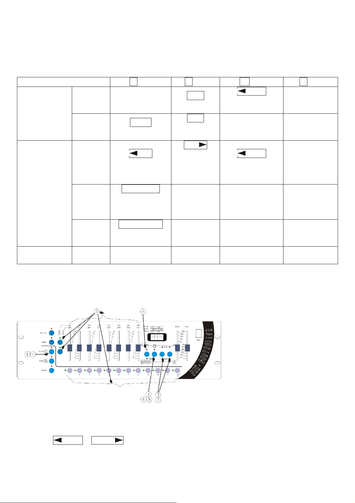
The schematic diagram of the edit scene panel:
Process steps of the scene editing:
① Press SCENE button in excess of 2 seconds. The indicator light glitters. Enter the edit scene state.
② Use the Scene & Scene button to choose the scene serial number.
If you want to edit the current scene, then run the step 3.
If you want to delete the current scene, then run the step 5.
Page 23
LIGHT4ME DMX 192 v2
Instrukcja obsługi / User Manual
22
If you want to copy the current scene, then run the step 7.
③ Edit the current scene: use the number button 1-12 to choose the light number, then with the
cooperation of the Page1 & Page2 button, use the handspike Ch1/Ch9-Ch8/Ch16 to set the value of
each channel.
④ Save the editing scene: press the SAVE button in excess of 2 seconds. When the panel indicator
light and the screen glitter once, the current editing scene is saved.
If you want to continue to edit other scene, run the step 2, choose another scene to edit; or run the
step 9 to exit the editing scene state.
⑤ Delete the current scene: press the DELETE button in excess of 2 seconds. The lighting of the
indicator light implies that the current scene is deleted.
If you want to continue to edit other scene, run the step 2, choose another scene to edit; or run the
step 9 to exit the editing scene state.
⑥ Copy the current scene: Press the COPY button, until the indicator light. Enter the copy state, the
contents of the current scene as the source of the scene content.
⑦ Use the Scene& Scene button to choose the scene serial number which is used to store the
contents of the scene to copy. The serial number is the target serial number.
⑧ Press the COPY button again. The indicator go out. Complete the copy process, then the contents
of the source scene to cover the contents of the target scene.
If you want to continue to edit other scene, run the step 2, choose another scene to edit; or run the
step 9 to exit the editing scene state.
⑨ Exit the editing scene: press the SCENE button in excess of 2 seconds. The indicator light from
glittering to lighting. System switches from editing scene state.
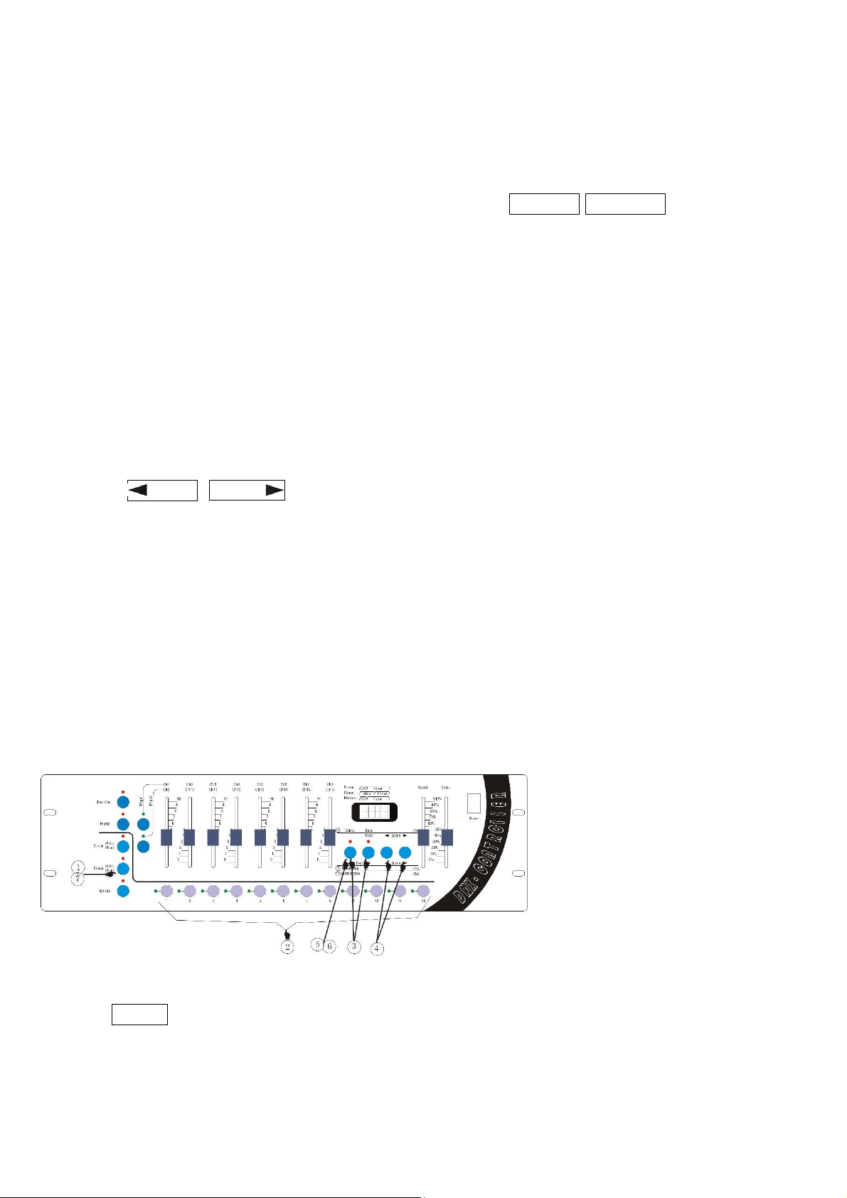
Edit chase
The schematic diagram of the edit chase panel:
Introduction of editing chase:
① Press Chase over 2 seconds and the indicator light will flash, meaning that the chase is in editing
state (digit will display “CHA”, prompting to select chase number).
Page 24
LIGHT4ME DMX 192 v2
Instrukcja obsługi / User Manual
23
② Select the number that you want: use Num Lock 1 – 12 to select the chase number (if the program
is empty, digit displays “00.—“. If step is zero, the number of the saved scene in this step will be dis-
played, such as “00.08”.
If you want to delete the current chase, execute the ⑤ step.
③ Select program step: Step and Step buttons used to select the step of the program that you
want to edit.
If you want to delete the current chase, please execute the ⑥ step.
④ Select the scene number: use Scene and Scene to select a scene number. It will be saved in
the chase step selected in the ③ step.
If you want to edit other steps of the current chase, execute the ③ repeatedly.
⑤ Delete current program: press Delete button over 3 seconds and the indicator light will flash 2 times,
then the current chase will be deleted (digit will display ”00.--”).
If you want to edit other steps of the current chase, execute the ③ repeatedly.
⑥ Delete the current step of the chase: press Delete button over 1 second and the pilot lamp will flash
1 time, then the current step will be deleted.
If you want to edit other steps of the current chase, execute the ③ repeatedly.
⑦ Exit the editing state of the chase of linear light: press Chase button over 1 second and the pilot will
light constantly after flashing, then the state will be switched to state of running chase of the linear
light.
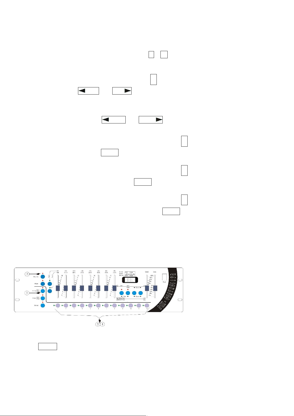
Running scene
The schematic diagram of the running scene panel:
Introduction of running scene’s step:
① Press Scene key and the lights are always on, meaning having entering the state of running scene.
② Select the scene number: use Num Lock 1-12 to choose the number you want.
③ If you want to output black scene, press blackout and if the indicator light is on, the effect of black
scene is being out or the effect is executed.
Page 25
LIGHT4ME DMX 192 v2
Instrukcja obsługi / User Manual
24
④ Close the scene’s output: use the Num Lock to select the number of the scene that you want to
close.
Running chase
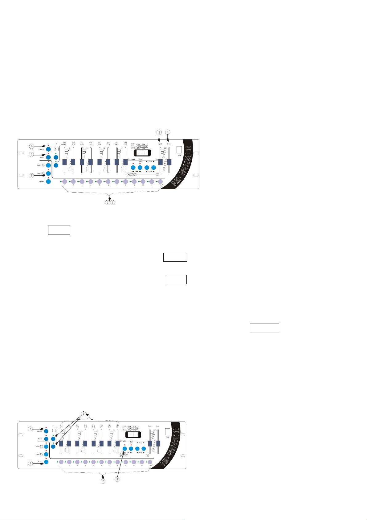
The schematic diagram of the running chase panel:
Introduction of running the chase:
① Press Chase to light the indicator light.
② Select the chase number you want: use Num Lock 1-12 to select the number.
③ Adjust the setting-time: adjust the clipper Speed to adjust the setting-time of the chase steps. The
top means the shortest time and the bottom the longest.
④ Adjust the shading-time: adjust the clipper Cross to adjust the shading-time of the chase step. The
top means non-shading and the more declined the longer shading-time.
⑤ Run by sound-activated: if you need to activate chase in the way of sound-activated, press Music
to make the lamp on, meaning having entered the state of sound-activated. If the lamp is off, it means
the sound-activated state is off.
⑥ Outputting black scene: if you need to output black scene, press Blackout key so that you can
choose to whether output black scene or not.
⑦ Exit the running chase: use Num Lock 1-12 to select the running chase number and the chase will
be closed.
Manual operation
The schematic diagram of the manual operation panel:
Page 26
LIGHT4ME DMX 192 v2
Instrukcja obsługi / User Manual
25
The definition of the process steps of the manual operation:
① Enter the manual state: press the MANUAL button, make the indicator light constantly shinning,
and enter manual operation state.
② Choose the manual lights: use the number button 1-12 to choose the number of lights.
③ Modify the number of channels: with the cooperation of the Page1 & Page2 button, the channel
handspike can realize the purpose of manual control of the lights. Press Page1 button, the indicator
light on, handspike correspond to Ch1-Ch8; press Page2 button, the indicator light on, handspike
correspond to Ch9-Ch16, realize the switch operation of the 16 channels.
④ Cleanout the manual state: press DELETE button, clean out the output state which was set on the
manual state.
⑤ The effect of blackout: press BLACKOUT button, switch the output.
The copy operation for the controller’s data
The operation for outputting the chase
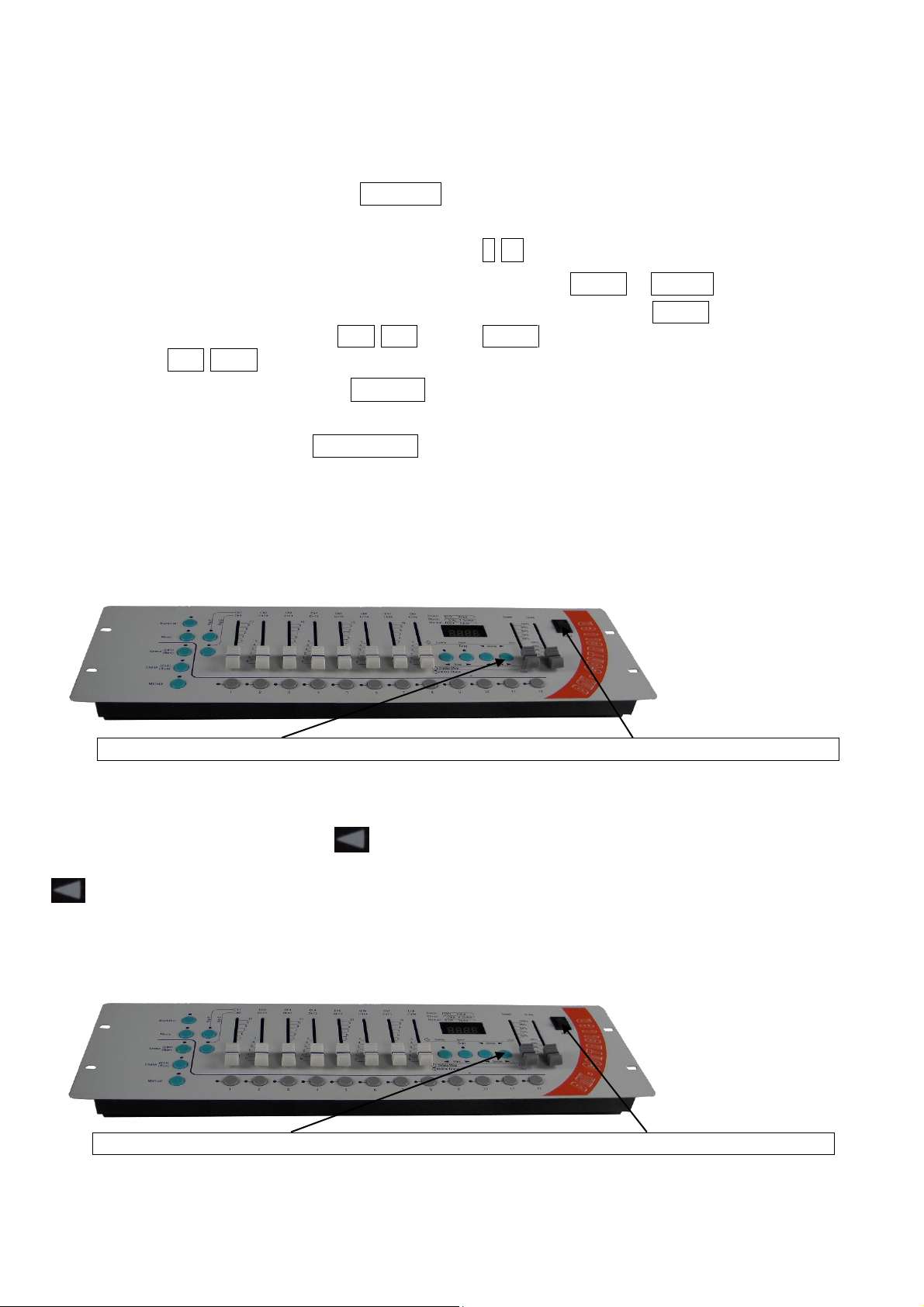
1. Keep pushing the button before open the power switch. 2. Then open the power switch.
1. Connect the “controller for chase outputting” with “controller for chase inputting” with the special
cable for data copying and connect both controllers with the power.
2. Keep pushing the scene button “ ” on the “controller for chase outputting”, then open the power
switch. It will go into the “outputting state” after the display shows “SE.xx” and just stop pushing
“ ”.
The operation for inputting the chase
1. Keep pushing the button before open the power switch. 2. Then open the power switch.
Page 27
LIGHT4ME DMX 192 v2
Instrukcja obsługi / User Manual
26
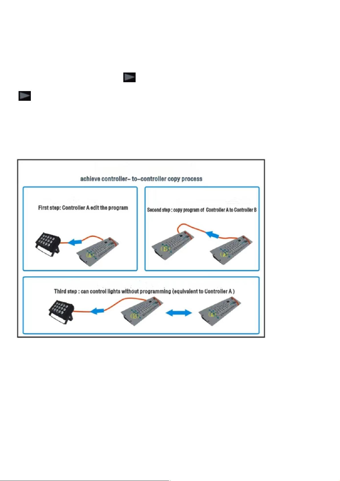
1. Connect the “controller for chase outputting” with “controller for chase inputting” with the special
cable for data copying and connect both controllers with the power.
2. Keep pushing the scene button “ ” on the “controller for chase outputting”, then open the power
switch. It will go into the “outputting state” after the display shows “RE.xx”, and just stop pushing
“ ”.
3. Now it is going into the process of copying, and the display on the “controller for chase inputting” will
show the last 2 numbers growing up. Until it shows “END”, all copying is done. Then you can close the
power and extract the copy cable. And after restarting the “controller for chase inputting”, the user can
use it to control the lightings.
The flow chart of the data copying operation
Information about used electrical and electronic equipment
The main goal of European and national law regulations is to reduce the amount of waste produced
from used electrical and electronic equipment, to ensure an appropriate level of collection, recovery
and recycling of used equipment, and to increase public awareness of its harmfulness to the environment, at each stage of use of electrical and electronic equipment. Therefore, it should be pointed out
that households play a key role in contributing to reuse and recovery, including recycling of used equipment. The user of electrical and electronic equipment – intended for households – is obliged to return
it to authorized collector after its use. However, it should be remembered that products classified
as electrical or electronic equipment should be disposed of at authorized collection points.
 Loading...