

Page 1
Liftup Inc. | 4809 Ehrlich Road | Suite 105 | FL – 33624, Tampa | T: +1 844 543 8878 | M: [email protected] | www.liftup.us
•
User manual
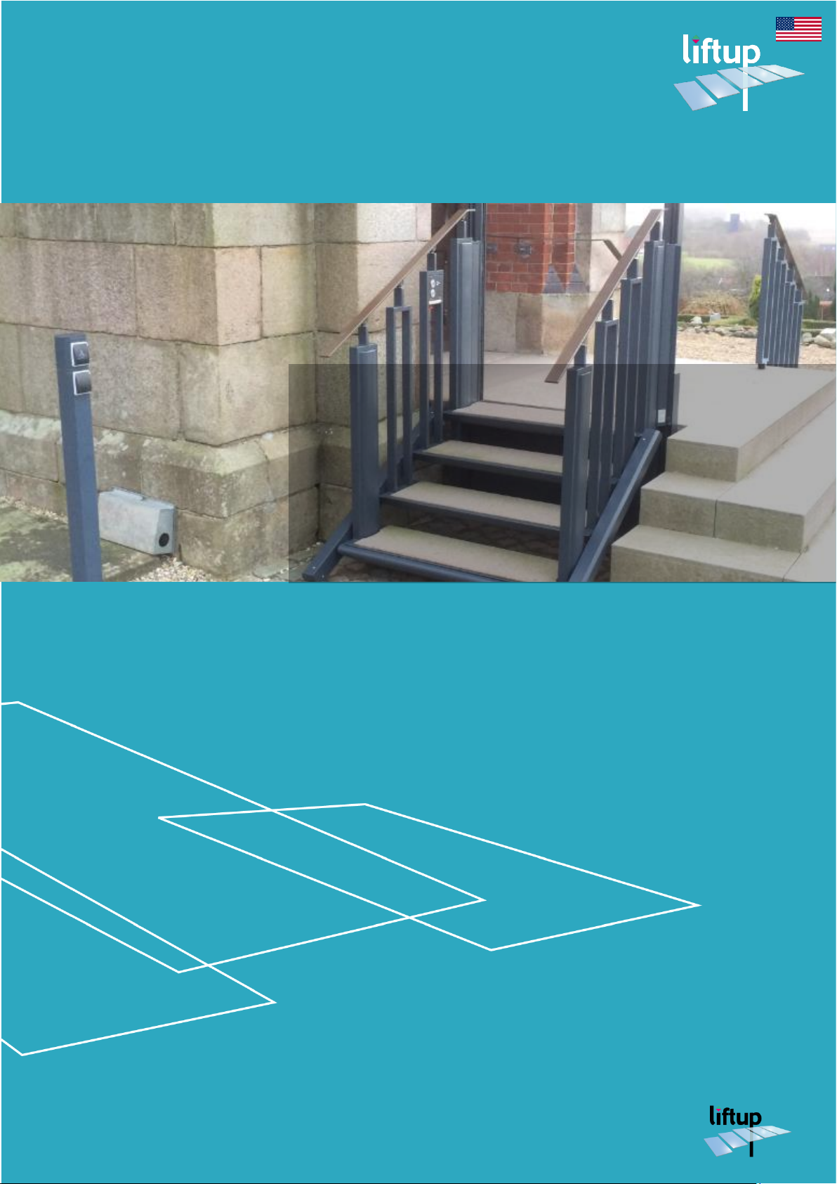
FlexStep V2
USER MANUAL – FLEXSTEP V2 – US VERSION 1.3
Page 2

USER MANUAL – FLEXSTEP V2 – US VERSION 1.3
Liftup Inc. | 4809 Ehrlich Road | Suite 105 | FL – 33624, Tampa | T: +1 844 543 8878 | M: [email protected] | www.liftup.us
2
Contents
1. Foreword ................................................................................................................................................... 4
2. Declarations .............................................................................................................................................. 5
2.1 Regulatory Approvals ........................................................................................................................ 8
2.2 EC declaration of conformity .......................................................................................................... 9
3. Type certificate ......................................................................................................................................10
4. Intended use ...........................................................................................................................................11
5. Technical specifications ........................................................................................................................12
6. Safety instructions .................................................................................................................................15
6.1 Installation and maintenance .........................................................................................................15
6.2 Unintended movements of FlexStep V2.....................................................................................15
6.3 Lift movement ...................................................................................................................................15
6.4 Avoiding personal injury .................................................................................................................15
6.5 Overload of the lift ..........................................................................................................................15
6.6 Personal safety ..................................................................................................................................16
6.7 Anti-crushing .....................................................................................................................................16
6.8 Infrared anti-crushing feature ........................................................................................................17
6.9 Barriers ...............................................................................................................................................17
6.10 Handling ..............................................................................................................................................18
6.11 Emergency lighting ...........................................................................................................................18
7. Functionality ...........................................................................................................................................18
8. Assembly .................................................................................................................................................19
9. Start-up ....................................................................................................................................................19
10. Operating the FlexStep V2 .................................................................................................................19
10.1 Daily use .............................................................................................................................................20
10.2 Operating FlexStep V2 from the TOP level ..............................................................................20
10.3 Operating FlexStep V2 from the BOTTOM level ....................................................................21
10.4 Operating FlexStep V2 on the platform .....................................................................................21
10.5 Return to stairs and auto-return ..................................................................................................22
10.6 Emergency stop ................................................................................................................................22
10.7 ON/OFF switch ................................................................................................................................22
10.8 Audible alarms ..................................................................................................................................23
11. Operability ..............................................................................................................................................25
11.1 Battery backup ..................................................................................................................................25
11.2 Calibration following emergency stop/power failure ..............................................................25
Page 3

USER MANUAL – FLEXSTEP V2 – US VERSION 1.3
Liftup Inc. | 4809 Ehrlich Road | Suite 105 | FL – 33624, Tampa | T: +1 844 543 8878 | M: [email protected] | www.liftup.us
3
12. Maintenance ............................................................................................................................................26
13. How to pair the transmitter and receiver ......................................................................................28
13.1 Remote control and receiver ........................................................................................................28
13.2 Wireless call station and receiver ................................................................................................29
14. Installation and handover form ..........................................................................................................30
15. Maintenance checklist ..........................................................................................................................31
16. Service logbook .....................................................................................................................................33
17. Spare parts and accessories ................................................................................................................34
18. Disassembly ............................................................................................................................................35
19. Disposal ...................................................................................................................................................35
20. Right of complaint .................................................................................................................................35
Page 4

USER MANUAL – FLEXSTEP V2 – US VERSION 1.3
Liftup Inc. | 4809 Ehrlich Road | Suite 105 | FL – 33624, Tampa | T: +1 844 543 8878 | M: [email protected] | www.liftup.us
4
1. Foreword
Congratulations on your new FlexStep V2 –an aesthetic and innovative 2-in-1 solution providing
you with both an ordinary staircase and a sophisticated wheelchair lift – be it in your home,
office or other place.
This is an original user manual for your new FlexStep V2.
It is important to read this manual before using the lift
Setup and installation MUST be undertaken by a qualified Liftup service technician, so as to
ensure correct assembly. Improper assembly can lead to unintended risk of personal injury.
FlexStep V2 is an elegant combination of regular stairs and wheelchair lift, which easily provides
wheelchair users and the walking-impaired access between two levels.
The lift is easy to operate using operating panels mounted on the wall, on the lift, or by means
of a remote control.
Page 5

USER MANUAL – FLEXSTEP V2 – US VERSION 1.3
Liftup Inc. | 4809 Ehrlich Road | Suite 105 | FL – 33624, Tampa | T: +1 844 543 8878 | M: [email protected] | www.liftup.us
5
2. Declarations
Corporate Office:
Manufacturer
Liftup Inc.
4809 Ehrlich Road
Suite 105
FL – 33624, Tampa
Phone: +1 844 543 8878
www.liftup.us
Liftup A/S
Hagensvej 21
DK–9530 Stoevring
Denmark
Phone: +45 9686 3020
www.liftup.dk
Copyright and Trademarks
© Liftup A/S. All rights reserved.
Liftup, the Liftup logo and Liftup are trademarks of Liftup A/S, registered in the United States
and in other countries. All other trademarks are the property of their respective owners.
The following Product Limited Warranty gives Resellers specific legal rights. You may have
others, which vary from state/jurisdiction to state/jurisdiction.
Product Limited Warranty
Subject to the terms and conditions set forth herein, Liftup A/S (
“Liftup”
) makes the following
warranty only to its Resellers who purchase the FlexStep V2 product (
“Product”
) directly from
Liftup: for a period of one (1) year from the date of shipment from Liftup, the Product will
substantially conform to Liftup’s standard published specifications for the Product and the
Product hardware will be substantially free from defects in materials and workmanship. The
foregoing warranty shall not apply to embedded software/firmware components.
THIS PRODUCT LIMITED WARRANTY IS PROVIDED TO RESELLERS AND TO RESELLERS
ONLY. RESELLER IS SOLELY RESPONSIBLE FOR ANY AND ALL WARRANTIES MADE TO
ITS CUSTOMERS, AND LIFTUP MAKES NO WARRANTIES, EXPRESS OR IMPLIED, AND
SHALL HAVE NO OBLIGATIONS OR LIABILITY TO RESELLER’S CUSTOMERS OR ENDUSERS OF THE PRODUCT. RESELLER SHALL NOT MAKE ANY REPRESENTATIONS OR
WARRANTIES ON LIFTUP’S BEHALF, AND SHALL FULLY INDEMNIFY, DEFEND AND
HOLD LIFTUP HARMLESS FROM ANY BREACH OF THE FOREGOING. IF RESELLER
DISTRIBUTES PRODUCT TO END-USER CUSTOMERS, RESELLER SHALL BE SOLELY
RESPONSIBLE FOR PREPARING AND PROVIDING PRODUCT WARRANTIES AND
PRODUCT LITERATURE TO END-USERS.
Warranty Remedies
If the Product fails during the warranty period for reasons covered by this Product Limited
Warranty and Reseller notifies Liftup of such failure during the warranty period, Liftup is at
option to repair OR replace the nonconforming Product, OR refund the purchase price paid by
Reseller for the Product, provided that Reseller returns the Product to Liftup in accordance
with Liftup’s standard return material authorization procedures or as otherwise instructed by
Liftup.
Page 6

USER MANUAL – FLEXSTEP V2 – US VERSION 1.3
Liftup Inc. | 4809 Ehrlich Road | Suite 105 | FL – 33624, Tampa | T: +1 844 543 8878 | M: [email protected] | www.liftup.us
6
Warranty Exclusions and Disclaimers
The foregoing Product Limited Warranty shall only apply in the event and to the extent that (i)
the Product is properly and correctly installed, configured, interfaced, maintained, stored and
operated in accordance with Liftup’s specifications, and (ii) the Product is not modified or
misused. This Product Limited Warranty shall not apply to, and Liftup shall not be responsible
for, defects or performance problems resulting from: (a) the combination or utilization of the
Product with hardware or software products, information, data, systems, interfaces, services or
devices not made, supplied or specified by Liftup; (b) the operation of the Product under any
specifications other than, or in addition to, Liftup’s standard published specifications for the
Product; (c) the unauthorized installation, modification or use of the Product; (d) damage caused
by: accident, lightning or other electrical discharge, water immersion or spray, or exposure to
environmental conditions for which the Product is not intended; or (e) normal wear and tear
on consumable parts, including by way of example and without limitation, batteries.
LIFTUP DOES NOT WARRANT OR GUARANTEE THE RESULTS OBTAINED THROUGH
THE USE OF THE PRODUCT. THE FOREGOING TERMS OF THE PRODUCT LIMITED
WARRANTY STATE LIFTUP’S ENTIRE LIABILITY, AND RESELLER’S EXCLUSIVE REMEDIES,
RELATING TO THE USE AND PERFORMANCE OF THE PRODUCT EXCEPT AS
OTHERWISE EXPRESSLY PROVIDED FOR IN THIS PRODUCT LIMITED WARRANTY, THE
PRODUCT, ACCOMPANYING DOCUMENTATION AND MATERIALS, AND/OR ANY
EMBEDDED SOFTWARE/FIRMWARE AND UPDATES THERETO ARE PROVIDED “AS-IS”
AND WITHOUT EXPRESS OR IMPLIED WARRANTIES OF ANY KIND, BY EITHER LIFTUP
OR ANYONE WHO HAS BEEN INVOLVED IN ITS CREATION, PRODUCTION,
INSTALLATION OR DISTRIBUTION, INCLUDING, BUT NOT LIMITED TO, THE IMPLIED
WARRANTIES OF MERCHANTABILITY AND FITNESS FOR A PARTICULAR PURPOSE,
TITLE AND NONINFRINGEMENT. THE STATED EXPRESS WARRANTIES ARE IN LIEU OF
ALL OBLIGATIONS OR LIABILITIES ON THE PART OF LIFTUP ARISING OUT OF, OR IN
CONNECTION WITH, THE PRODUCT. WITHOUT LIMITING THE GENERALITY OF THE
FOREGOING:
THE PRODUCT MAY CONTAIN TECHNOLOGY THAT IS NOT FAULT TOLERANT AND
IS NOT DESIGNED, MANUFACTURED OR INTENDED FOR USE IN ENVIRONMENTS OR
APPLICATIONS IN WHICH THE FAILURE OF THE PRODUCT WOULD LEAD TO DEATH,
PERSONAL INJURY OR SEVERE PHYSICAL OR ENVIRONMENTAL DAMAGE OR SEVERE
FINANCIAL LOSS. ANY USE OR DISTRIBUTION BY RESELLER OR ITS CUSTOMERS IN
CONNECTION WITH ANY SUCH ENVIRONMENT OR APPLICATION SHALL BE AT
RESELLER’S AND ITS CUSTOMERS’ SOLE RISK, AND LIFTUP SHALL HAVE NO LIABILITY
WHATSOEVER IN CONNECTION THEREWITH. RESELLER SHALL INDEMNIFY AND
HOLD LIFTUP AND ITS SUPPLIERS HARMLESS FROM ANY CLAIM BROUGHT AGAINST
LIFTUP WHICH ARISES FROM RESELLER’S USE OR DISTRIBUTION OF THE PRODUCT IN
CONNECTION WITH SUCH ENVIVRONMENTS OR APPLICATIONS. SOME STATES AND
JURISDICTIONS DO NOT ALLOW LIMITATIONS ON DURATION OR THE EXCLUSION
OF AN IMPLIED WARRANTY, SO CERTAIN OF THE ABOVE LIMITATIONS MAY NOT
APPLY TO EVERY RESELLER.
Page 7

USER MANUAL – FLEXSTEP V2 – US VERSION 1.3
Liftup Inc. | 4809 Ehrlich Road | Suite 105 | FL – 33624, Tampa | T: +1 844 543 8878 | M: [email protected] | www.liftup.us
7
Embedded Software/Firmware
The Product and associated tools, if any, may contain embedded software/firmware, which is
licensed, not sold, and is only for use within the Product as an integral part thereof. Such
embedded software/firmware (which includes all updates thereto) contains valuable trade
secrets and is proprietary to Liftup A/S and its suppliers. To the greatest extent permitted by
law, such embedded software/firmware may not be modified, copied, disassembled, decompiled
or reverse engineered. Liftup reserves all other rights.
Limitation of Liability
LIFTUP’S ENTIRE LIABILITY REGARDING THE PRODUCT SHALL BE LIMITED TO THE
AMOUNT ACTUALLY PAID BY RESELLER FOR THE PRODUCT. TO THE MAXIMUM
EXTENT PERMITTED BY APPLICABLE LAW, IN NO EVENT SHALL LIFTUP OR ITS
SUPPLIERS BE LIABLE FOR ANY INDIRECT, SPECIAL, INCIDENTAL OR CONSEQUENTIAL
DAMAGES WHATSOEVER UNDER ANY CIRCUMSTANCE OR LEGAL THEORY
RELATING IN ANY WAY TO THE PRODUCTS, ACCOMPANYING DOCUMENTATION
AND MATERIALS, AND ANY EMBEDDED SOFTWARE/FIRMWARE AND UPDATES
THERETO (INCLUDING, WITHOUT LIMITATION, DAMAGES FOR LOSS OF BUSINESS
PROFITS,
BUSINESS INTERRUPTION, LOSS OF DATA OR ANY OTHER PECUNIARY LOSS),
REGARDLESS OF WHETHER LIFTUP HAS BEEN ADVISED OF THE POSSIBILITY OF ANY
SUCH LOSS AND REGARDLESS OF THE COURSE OF DEALING BETWEEN LIFTUP AND
RESELLER. BECAUSE SOME STATES AND JURISDICTIONS DO NOT ALLOW THE
EXCLUSION OR LIMITATION OF LIABILITY FOR CONSEQUENTIAL OR INCIDENTAL
DAMAGES, THE ABOVE LIMITATION MAY NOT APPLY TO EVERY RESELLER.
Notices
Class B Statement – Notice to Users. This equipment has been tested and found to comply with
the limits for a Class B digital device, pursuant to Part 15 of the FCC rules. These limits are
designed to provide reasonable protection against harmful interference in a residential
installation. This equipment generates, uses, and can radiate radio frequency energy and, if not
installed and used in accordance with the instructions, may cause harmful interference to radio
communication. However, there is no guarantee that interference will not occur in a particular
installation. If this equipment does cause harmful interference to radio or television reception,
which can be determined by turning the equipment off and on, the user is encouraged to try to
correct the interference by one or more of the following measures:
• Reorient or relocate the receiving antenna.
• Increase the separation between the equipment and the receiver.
• Consult the dealer or an experienced radio/TV technician for help.
Changes and modifications not expressly approved by the manufacturer or registrant of this
equipment can void your authority to operate this equipment under Federal Communications
Commission rules.
Page 8

USER MANUAL – FLEXSTEP V2 – US VERSION 1.3
Liftup Inc. | 4809 Ehrlich Road | Suite 105 | FL – 33624, Tampa | T: +1 844 543 8878 | M: [email protected] | www.liftup.us
8
2.1 Regulatory Approvals
FCC/IC
The radio module contained in the FlexStep V2 and associated remote comply with the FCC
Part 15.249 and the Industry Canada requirements RSS-GEN, RSS-210
The radio module contained in the FlexStep V2 and associated remotes complies with Part 15
of the FCC rules and with Industry Canada license exempt standard(s). Operation is subject to
the following two conditions:
(1) This device may not cause harmful interference, and
(2) This device must accept any interference received, including interference that may cause
undesired operation.
The radio module contained in the FlexStep V2 and associated remotes are SAR test excluded
according to FCC KDB 447498, RSS102 and EN 62479 at separation distances larger than 5 mm
and less than 50 mm.
With respect to radiofrequency radiation exposure Information, it is declared; that this
equipment complies with FCC radiation exposure limits set forth for an uncontrolled
environment. This gives an extra margin, since the remote control normally, only is used in
“controlled environment” for approx. 30 seconds when lifting, and typically only a few times a
day.
FlexStep V2 contains:
Handheld Remote1
Wall mounted Remote2:
FCC ID:
2AK8H-MODULE1
FCC ID:
2AK8H-REMOTE1
FCC ID:
2AK8H-REMOTE2
IC:
22516-MODULE1
IC:
22516-REMOTE1
IC:
22516-REMOTE2
EU Declaration of Conformity: CE
(Machinery Directive and RED (Radio module and remote))
ASME 18.1 2014 (US/FDA)
The FlexStep V2 complies with key requirements of the ASME 18.1 Safety Standard for Platform
lifts and Stairway Chairlifts, section 5 “Private Residence Platform Lifts”. Please note that not all
possible configurations of the FlexStep V2 are in compliance – consult your reseller for further
information.
Page 9
USER MANUAL – FLEXSTEP V2 – US VERSION 1.3
Liftup Inc. | 4809 Ehrlich Road | Suite 105 | FL – 33624, Tampa | T: +1 844 543 8878 | M: [email protected] | www.liftup.us
9
2.2 EC declaration of conformity
Directive 2006/42/EC on machinery
Manufacturer: Liftup A/S
Address: Hagensvej 21, DK-9530 Støvring, Denmark
Telephone no.: +45 9686 3020
hereby declares that:
Lift: FlexStep V2
Combination stairlift for wheelchair users and the walking-impaired
Year: 2015
conforms to the key health and safety requirements of Directive 2006/42/EC on
machinery.
Relevant parts of the following were, for example, used in the assessment:
DS/EN 60204 Safety of machinery – Electrical equipment of machines.
DS/EN 13849-1 and -2 Safety-related parts of control systems
Director Flemming Eriksen
______________________ ______________________________
Title Name
Liftup A/S, Hagensvej 21, DK-9530 Støvring, Denmark
________________________________________________
Place
2015-10-01 _____________________________
Date Signature
Page 10
USER MANUAL – FLEXSTEP V2 – US VERSION 1.3
Liftup Inc. | 4809 Ehrlich Road | Suite 105 | FL – 33624, Tampa | T: +1 844 543 8878 | M: [email protected] | www.liftup.us
10
3. Type certificate
Page 11
USER MANUAL – FLEXSTEP V2 – US VERSION 1.3
Liftup Inc. | 4809 Ehrlich Road | Suite 105 | FL – 33624, Tampa | T: +1 844 543 8878 | M: [email protected] | www.liftup.us
11
4. Intended use
The FlexStep V2 is a motorized lift device intended as a means for a wheelchair user or a walking
impaired person to move from one level to another.
The lift application of the FlexStep V2 is solely for the use of wheelchair users or the walkingimpaired.
Read this user manual thoroughly before using the lift.
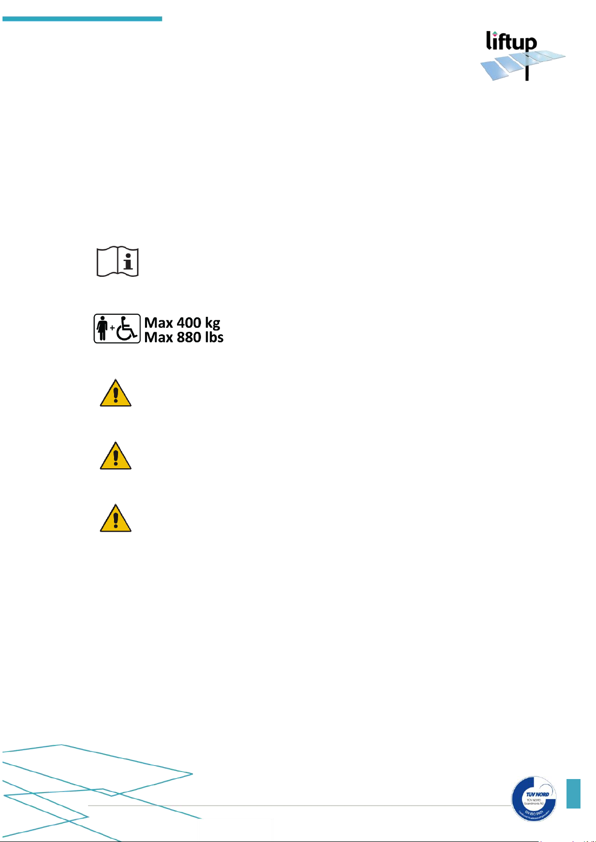
The maximum load is 400 kg (880 lbs) or a maximum of 2
persons evenly distributed on the platform.
IMPORTANT! The platform must NOT be used for goods transport,
including loaded pallets or other types of heavy loads.
IMPORTANT! No persons must be on the FlexStep V2 when it is moving to
or from stair mode.
IMPORTANT! The owner of this FlexStep V2 is obliged to maintain it
according to the Maintenance Guide in section 12.
Page 12
USER MANUAL – FLEXSTEP V2 – US VERSION 1.3
Liftup Inc. | 4809 Ehrlich Road | Suite 105 | FL – 33624, Tampa | T: +1 844 543 8878 | M: [email protected] | www.liftup.us
12
5. Technical specifications
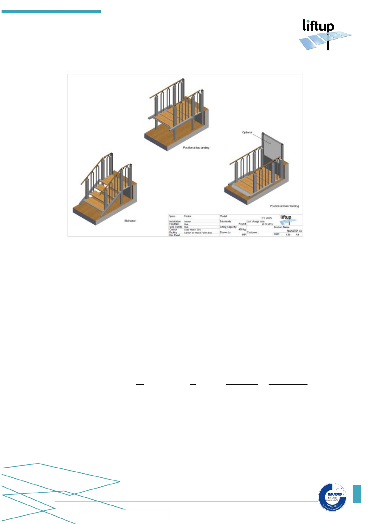
All scale drawings for 2+2, 3, 3+1, 4, 4+1, 5 and 6 step FlexStep V2 in standard widths
are available at www.flexstep.us
Technical specifications:
Power: 100 - 240 V/50 Hz (1.1A) Max: 90 W, Standby < 6 W
Lifting capacity: 400 kg (880 lbs) or 2 persons
Lifting height: 0 – 1250 mm (0 – 49.21”)
Platform size:
Internal dimensions: W 700/800/900/1000 mm (27.56/31.50/35.43/39.37”)
L 900 mm - 1800 mm (35.43 – 70.87”)
External dimensions: W 930 – 1230 mm (36.61 – 48.43”)
L 1095 - 2010 mm (43.13 – 79.13”)
Weight: 125 - 205 kg. (275.6 – 451.9 lbs)
Noise level: < 70 dB
Water and dust: >50V: IP67 (Power Supply) / <50V: IP23 / <10V: IPxx
Lifting speed/
temperature:
°C
°F
mm/second
inches/second
+40˚C - +5˚C
+104˚F - +41˚F
40 mm
1.57”
+5˚C - -10˚C
+41˚F - +14˚F
20 mm
0.79”
-10˚C - -20˚C
+14˚F - -4˚F
10 mm
0.39”
Max. 200 kg/440 lbs
-20˚C - -25˚C
-4˚F - -13˚F
10 mm
0.39”
Approval: Directive 2006/42/EC on machinery
Duty cycle: 2 min./5 min.
Battery capacity: 30 cycles at 25 ˚C / 77 ˚F - Fully charged = 5 hours
Flat battery: 10 min. charge = 1 trip
Page 13

USER MANUAL – FLEXSTEP V2 – US VERSION 1.3
Liftup Inc. | 4809 Ehrlich Road | Suite 105 | FL – 33624, Tampa | T: +1 844 543 8878 | M: [email protected] | www.liftup.us
13
If the FlexStep V2 is configured with “Remote Control” (supplementary equipment):
All radio components comply with the following standards:
EU 2014/53/EU, Radio Equipment Directive (RED)
FCC (USA) CFR 47 Part 15
EN 62479:2010 Human exposure
EN 300 440, v2.1.1 Electromagnetic compatibility + Radio spectrum Matters Draft
EN 301489-1, v2.2.0 Electromagnetic compatibility + Radio spectrum Matters Draft
EN301489-17, v3.2.0 Electromagnetic compatibility + Radio spectrum Matters
AS/NZS 4268 Radio Equipment and Systems –Short Range devices
AS/NZS 2772.2 Radio Frequency Fields (mean power < 1 mW)
Module1:
2,4GHZ Short Range devices. FCC ID: 2AK8H-MODULE1
Receiver Class 3
Dimensions (L x W x H): 72 x 33 x 10mm / 2,83 x 1,30 x 0,40 in.
Weight: 10 g (0,035 lbs.)
Frequency’s: 2,410GHz 2,435GHz and 2,460GHz
Duty cycle: < 1% (only TX for pairing Remotes)
Power: < 0,6mW Controlled environment
Supply: 5,6 Volt 30mA
Water and dust: IP xx Shall be mounted inside Liftup products
Working temperature: +5ºC to +40ºC/ 41ºF to 104ºF
Storage temperature: -25ºC to +70ºC / 13ºF to 158ºF
Expected service life: > 5 years
Handheld Remote 1:
2,4GHZ Short Range devices. FCC ID: 2AK8H-REMOTE1
Receiver Class 3
Dimensions (L x W x H): 96 x 47 x 24mm / 3,79 x 1,85 x 0,95 in.
Weight: 48 g (0,11 lbs.)
Frequency’s: 2,410GHz 2,435GHz and 2,460GHz
Duty cycle: < 1%
Power: <0,6mW Controlled environment, Hold to run
Battery: 3 Volt CR2032
Water and dust: IP 42
Working temperature: +5ºC to +40ºC / 41ºF to 104ºF
Storage temperature: -25ºC to +70ºC / 13ºF to 158ºF
Expected service life: > 5 years
Page 14

USER MANUAL – FLEXSTEP V2 – US VERSION 1.3
Liftup Inc. | 4809 Ehrlich Road | Suite 105 | FL – 33624, Tampa | T: +1 844 543 8878 | M: [email protected] | www.liftup.us
14
Wall mounted Remote2:
2,4GHZ Short Range devices. FCC ID: 2AK8H-REMOTE2
Receiver Class 3
Dimensions (L x W x H): 80 x 64 x 33mm / 3,15 x 2,52 x 1,30 in.
Weight: 75 g (0,17 lbs.)
Frequency’s: 2,410GHz 2,435GHz and 2,460GHz
Duty cycle: < 1%
Power: < 0,6mW Controlled environment, Hold to run.
Battery: 3 Volt CR2032
Water and dust: IP 42
Working temperature: +5ºC to +40ºC/ 41ºF to 104ºF
Storage temperature: -25ºC to +70ºC / 13ºF to 158ºF
Expected service life: > 5 years
Right reserved to make technical modifications
Page 15

USER MANUAL – FLEXSTEP V2 – US VERSION 1.3
Liftup Inc. | 4809 Ehrlich Road | Suite 105 | FL – 33624, Tampa | T: +1 844 543 8878 | M: [email protected] | www.liftup.us
15
6. Safety instructions
6.1 Installation and maintenance
Do NOT try to install or service your FlexStep V2 yourself – this MUST be done
by an authorised* service technician.
Do NOT remove the protective or safety plates, as this may lead to personal
injury.
6.2 Unintended movements of FlexStep V2
If during the use of your FlexStep V2 movement or action occurs which is not described in this
manual, stop the unit and call technical assistance.
Should your FlexStep V2 not move with plane movement as a platform, calibrate the lift by
running the platform down to floor level. If the problem continues, call technical assistance.
6.3 Lift movement
The space under the lift must be kept free of all objects which may impair its downward
movement. Otherwise the lift cannot be moved to the lowest level and thus not be used as a
wheelchair lift.
Should an object hinder lift downward movement, the anti-crushing safety feature will be
activated (please see section 6.7)
6.4 Avoiding personal injury
WARNING! Do NOT move the FlexStep V2 from stairs to platform or the
reverse when persons or objects are on the stairs.
To avoid personal injury, it is NOT permitted to use the FlexStep V2 when someone is at risk
of being injured by crushing, cutting, falling, slipping, or similar.
It is important that the operator/user ensures that the lift can move without putting anyone or
anything at risk.
Be extra careful when there are small children, or elderly or disabled people on or near the
stairs/platform, as these groups cannot always be expected to be able to foresee the possible
consequences of lift movement.
6.5 Overload of the lift
To avoid damage to the lift in the event of overload (max. 400 kg (881.8 lbs) evenly distributed),
it is fitted with an overload cut-out, which when triggered halts the lift and issues an audible
alarm (please see section 10.8). In such cases, run the lift down in order to exit it.
*Has completed a Liftup product and service course
Page 16
USER MANUAL – FLEXSTEP V2 – US VERSION 1.3
Liftup Inc. | 4809 Ehrlich Road | Suite 105 | FL – 33624, Tampa | T: +1 844 543 8878 | M: [email protected] | www.liftup.us
16
6.6 Personal safety
FlexStep V2 is fitted with various safety features which ensure that the user or other people are
not injured when using the lift.
WARNING! Although the lift comes fitted with various safety features, never
use it if persons or animals are close by, as there may otherwise be a risk of
crushing. Never allow children to play with the lift.
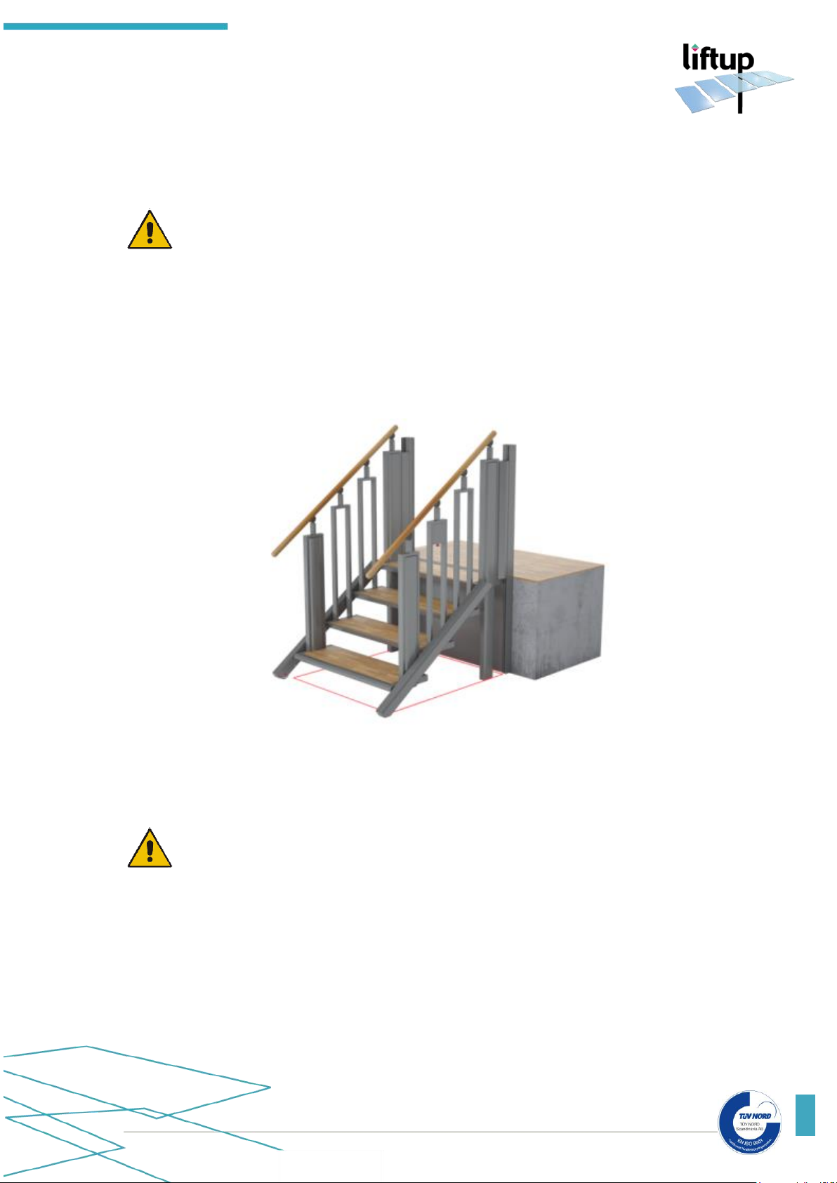
6.7 Anti-crushing
Beneath the entire lift a number of pressure plates (anti-crushing) are fitted which are activated
if an object is going to be crushed below. When this feature is activated, the lift stops and then
runs approx. 2 cm (0.8 in) upwards, while at the same time an audible alarm is issued (please see
section 10.8).
If the anti-crushing feature is activated, release the operating button. Remove any objects under
the lift and it can then be run to the “lower landing” or “staircase” states. (If needed, run the lift
upwards so you can more easily remove objects underneath it).
IMPORTANT! Keep in mind that when the lift is used outdoors, leaves, branches
and snow can affect the anti-crushing safety feature, and so you should check
regularly that the lift will not be obstructed when moving downward.
Page 17
USER MANUAL – FLEXSTEP V2 – US VERSION 1.3
Liftup Inc. | 4809 Ehrlich Road | Suite 105 | FL – 33624, Tampa | T: +1 844 543 8878 | M: [email protected] | www.liftup.us
17
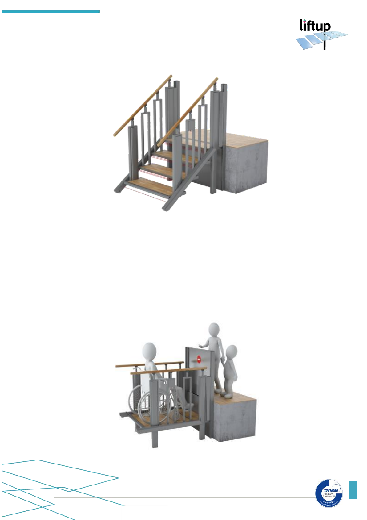
6.8 Infrared anti-crushing feature
Infrared sensors are fitted between the steps in order to avoid crushing between them.
Infrared sensors prevent crushing between the steps
If the IR sensors are disrupted when the FlexStep V2 moves from staircase to platform or the
reverse, movement will stop, and an audible alarm will sound (please see section 10.8).
6.9 Barriers
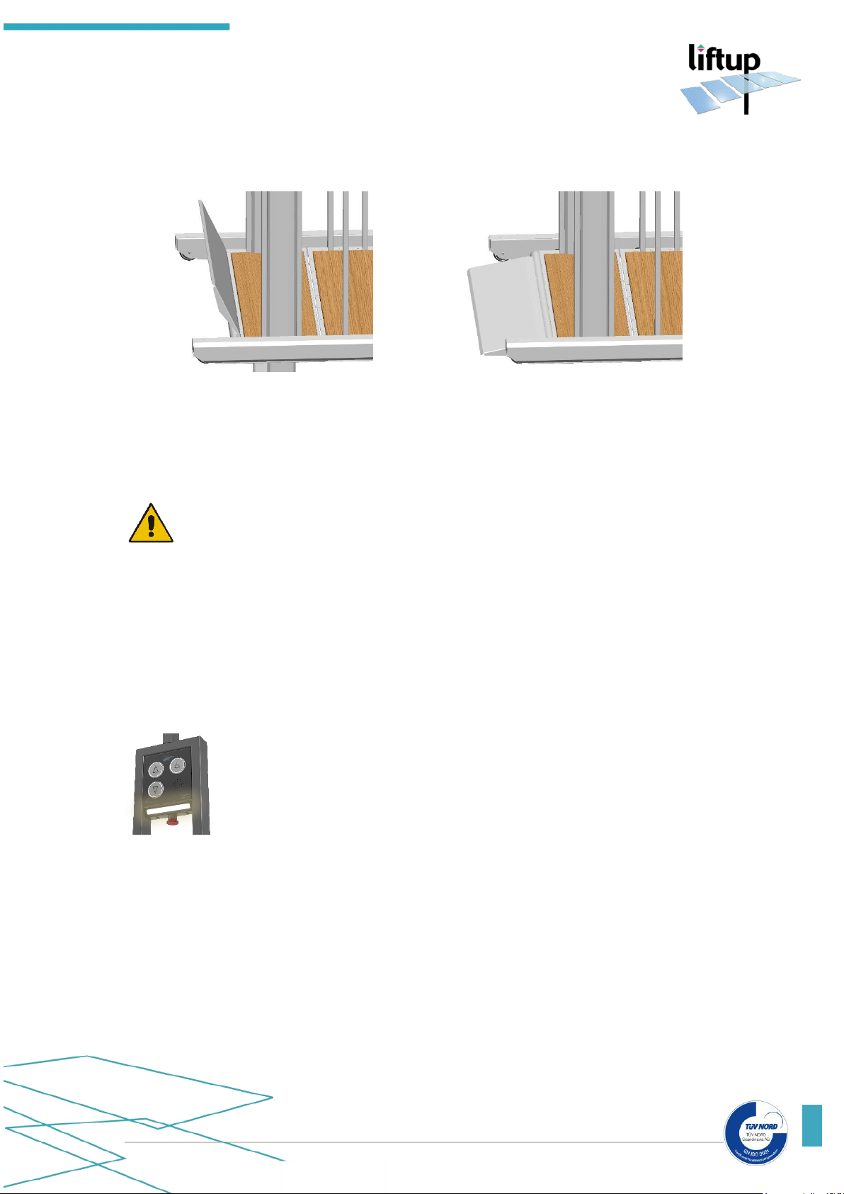
When the lift operates, the ramp will first rise and lock in place before the lift begins to move.
The ramp is now acting as a barrier to prevent the wheelchair from rolling off the platform.
When the lift is run down to the “lower landing” position, the ramp will automatically lower
(keep the button pressed) and act as a drive-on/drive-off ramp.
If the lift is fitted with a safety barrier (supplementary equipment) at the top level,
it will close before the lift begins to move.
Page 18
USER MANUAL – FLEXSTEP V2 – US VERSION 1.3
Liftup Inc. | 4809 Ehrlich Road | Suite 105 | FL – 33624, Tampa | T: +1 844 543 8878 | M: [email protected] | www.liftup.us
18
The safety barrier will always be closed and locked when the lift is not at the top level. The ramp
is raised when the lift is not at the bottom level.
The ramp rises and locks
The ramp sinks to floor level
6.10 Handling
The lift is normally supplied by your dealer, who also takes care of installation.
IMPORTANT! Do not try to move the lift manually, as this can lead to personal
injury. The product should be moved and handled using suitable lifting equipment
(pallet-truck, roller plate, or similar).
Do not subject the lift to severe knocks/blows as these can affect functionality.
Keep the associated remote control (supplementary equipment) dry and do not subject it to
severe blows. Cleaning may only be performed using a well-wrung cloth.
6.11 Emergency lighting
In the event of power failure or if power to the control system gets disconnected for some other reason, the system will automatically switch to
backup mode. This means that the system will continue to work, as the lift will
then be powered by a backup battery. The illuminations on the operating panel
will still be alight.
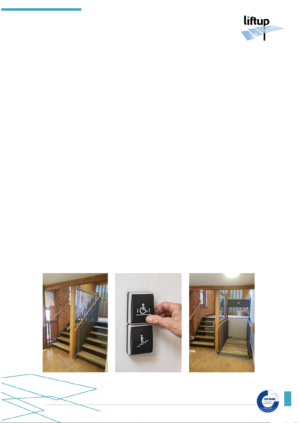
7. Functionality
The lift is a so-called “hold-to-run operated” lift, i.e. the buttons must be pressed and held for
the entire motion.
The lift is simple to operate: The user calls it by pressing one of the buttons on the wall, or by
using the associated remote control (supplementary equipment). When the user is on the platform, it is operated by means of a side panel, from which the user can choose between moving
to the upper or lower levels.
Page 19
USER MANUAL – FLEXSTEP V2 – US VERSION 1.3
Liftup Inc. | 4809 Ehrlich Road | Suite 105 | FL – 33624, Tampa | T: +1 844 543 8878 | M: [email protected] | www.liftup.us
19
8. Assembly
The lift is installed by an authorised service technician.
Do NOT attempt to transport/move or uninstall your FlexStep V2, or to repair it. These actions
MUST be undertaken by an authorised service technician.
Improper assembly can pose risks to user personal safety. Liftup disclaims any liability if assembly
and installation are not performed by an authorised service technician.
For more information or materials on assembly, contact your dealer (please see
https://www.liftup.us/distributors/# ).
9. Start-up
FlexStep V2 should always be connected to the AC mains and be switched on.
Normally the lift is in constant stand-by mode, i.e. it is ready for use as soon as one of the
operating buttons is pressed.
If the emergency stop is pressed in – or the lift is switched off by a key switch (supplementary
equipment), it must be released/switched on before the lift can be put into use (please see more
about this in section 10).
10. Operating the FlexStep V2
The FlexStep V2 is a unique 2-in-1 application designed to function both as an ordinary staircase
and as a wheelchair lift. Basically, the FlexStep V2 is an ordinary staircase, but with the simple
pushbuttons it is easily folds up/down to a platform and is transformed to a wheelchair lift.
Page 20
USER MANUAL – FLEXSTEP V2 – US VERSION 1.3
Liftup Inc. | 4809 Ehrlich Road | Suite 105 | FL – 33624, Tampa | T: +1 844 543 8878 | M: [email protected] | www.liftup.us
20
10.1 Daily use
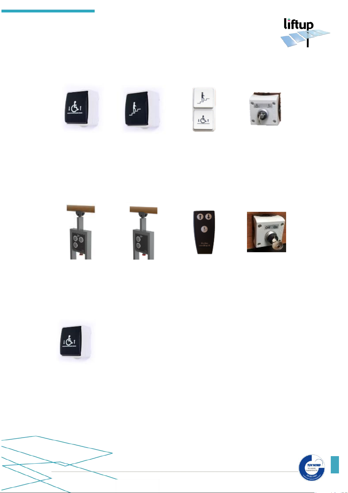
FlexStep V2 is operated by means of two operating panels (each available as standard, flush
mounted (FUGA) or key-operated call station) at the upper and lower levels respectively.
Standard call stations
(wireless or wired)
Flush mounted
(FUGA) call stations
Key-operated
call station
Further it can be operated by means of pushbuttons on the platform handrails or by means of a
remote control (supplementary equipment). The remote control can replace the two operating
panels. Additionally, the lift can be switched on or off by means of a key switch (supplementary
equipment).
Lift call station push buttons on the handrail
with/without alarm bell (supplementary
equipment)
Remote control
(supplementary
equipment)
Key switch
(supplementary
equipment)
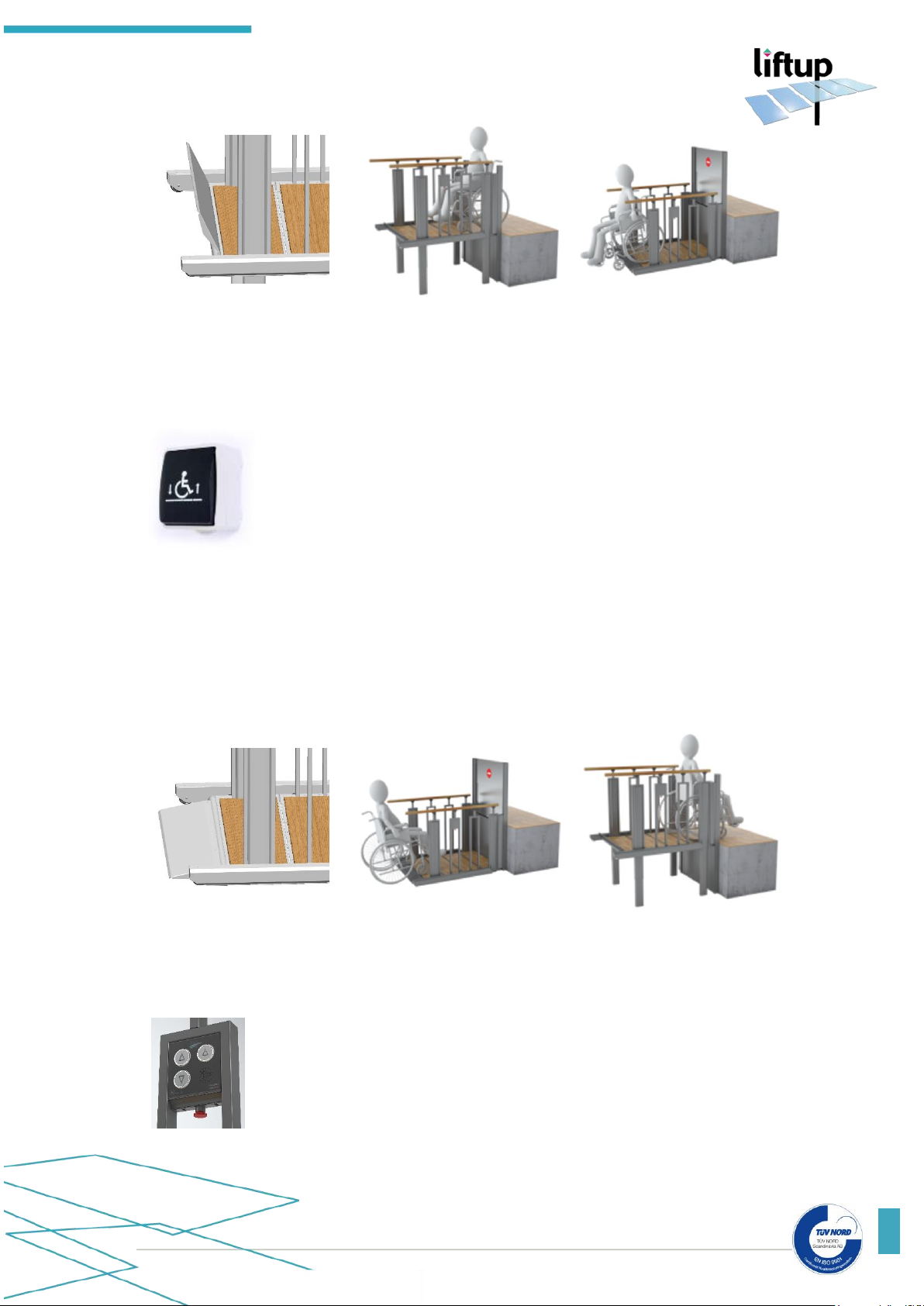
10.2 Operating FlexStep V2 from the TOP level
In order to call the stairs to a platform at the TOP level, press and hold
the top button with the wheelchair symbol.
The stairs lift the ramp into an anti-roll-off barrier which will then be locked in the raised position
(Fig. 1). The stairs move down into a platform at the BOTTOM level, which then rises to the
TOP level (Fig. 2). Drive carefully onto the platform (use the wheelchair brake), press the "down
arrow" on the operating panel, and the platform will sink to the BOTTOM level. Now the antiroll-off barrier will lower and act as a ramp (Fig. 4). Drive carefully off the platform (Fig. 3).
Page 21
USER MANUAL – FLEXSTEP V2 – US VERSION 1.3
Liftup Inc. | 4809 Ehrlich Road | Suite 105 | FL – 33624, Tampa | T: +1 844 543 8878 | M: [email protected] | www.liftup.us
21
Fig. 1:
The ramp rises and locks in
place
Fig. 2:
Drive onto the platform
Fig. 3:
Drive off the platform
10.3 Operating FlexStep V2 from the BOTTOM level
In order to call the stairs to a platform at the BOTTOM level, press and
hold the bottom button with the wheelchair symbol.
The stairs lift the ramp into an anti-roll-off barrier which is then locked in the raised position
(Fig. 1). The stairs move down into a platform at the BOTTOM level, after which the anti-rolloff barrier lowers into an access ramp (Fig. 4). Drive carefully onto the platform (use the
wheelchair brake) (Fig. 5). Press the "up arrow" on the operating panel and the platform will rise
to the TOP level after the ramp has risen into an anti-roll-off barrier. Drive carefully off the
platform (Fig. 6).
Fig. 4:
The ramp lowers to floor level
Fig 5.:
Drive onto the platform
Fig 6.:
Drive off the platform
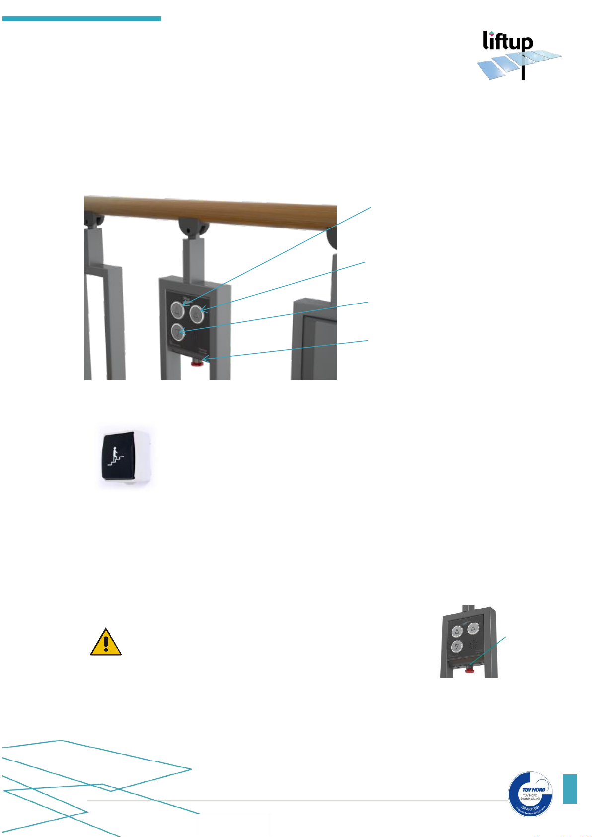
10.4 Operating FlexStep V2 on the platform
In order to operate the FlexStep V2 as a wheelchair lift when you are on
the platform, use the operating panel fitted to the stair handrails.
Page 22
USER MANUAL – FLEXSTEP V2 – US VERSION 1.3
Liftup Inc. | 4809 Ehrlich Road | Suite 105 | FL – 33624, Tampa | T: +1 844 543 8878 | M: [email protected] | www.liftup.us
22
This platform panel only functions when FlexStep V2 is in a platform state. An assistant can also
run the platform up or down using the operating panels on the wall or the remote control.
• To run the platform up, press and hold the “up arrow” button until the lift stops, and
any door or safety barrier has opened.
• To run the platform down, press and hold the “down arrow” button until the lift stops,
and the ramp has been lowered to the floor.
10.5 Return to stairs and auto-return
When the button with the stairs symbol is activated, FlexStep V2 converts
back to its normal state, which is staircase.
If no operating buttons or IR sensors have been activated for approx. 60 seconds (standard
setting), FlexStep V2 will automatically return to its normal state and work as a staircase. (An
audible alarm will sound during this process (please see section 10.8). This function can be
disconnected if the user does not want the lift to automatically revert to stairs.
10.6 Emergency stop
Should the lift make an unintended movement, or if it needs to
be stopped in order to avoid injury, press the EMERGENCY
STOP. To release the emergency stop, turn the button clockwise, and then the system is again ready for use.
10.7 ON/OFF switch
FlexStep V2 comes fitted with an ON/OFF switch. It is sited at the base of the control box on
the right-hand side. This button is used to disconnect the power supply to the lift. If the user
Lifting platform up
Lifting platform down
Emergency stop
Bell
(supplementary equipment)
Page 23
USER MANUAL – FLEXSTEP V2 – US VERSION 1.3
Liftup Inc. | 4809 Ehrlich Road | Suite 105 | FL – 33624, Tampa | T: +1 844 543 8878 | M: [email protected] | www.liftup.us
23
switches it off at the same time as activating the emergency stop, the lift will be completely
powered off.
The ON/OFF switch is used in the pairing of wireless call stations (please see section 13). Power
to the lift is switched on/off by activating the ON/OFF switch and the emergency stop (please
see section 11.1). When power is again returned to the lift (and the emergency stop is released),
the control system restarts (please see section 11.2).
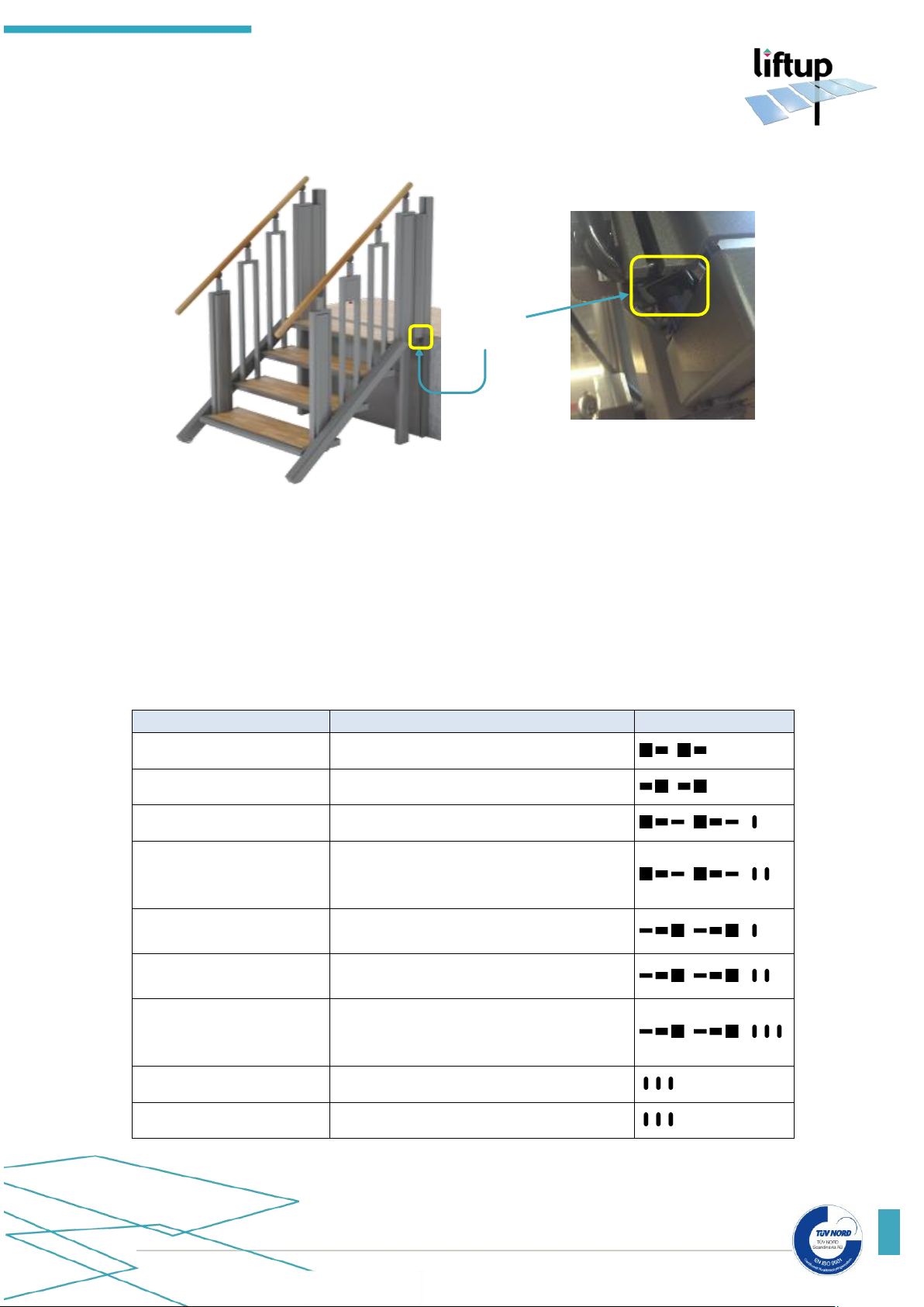
10.8 Audible alarms
If “speak” is installed on the lift this will be activated in the event of an alarm. Otherwise an
alarm tone will sound.
Speak
Activity/warning
Opening
The vertical safety barrier is opening
Closing
The vertical safety barrier is closing
Alarm: Overload alarm
The platform is overloaded.
Alarm: Battery fault – the
lift cannot be used
The battery has a fault.
Inadequate power supply (please see section 5 Technical Specifications)
Alarm:
Under pan switch activated
Remove the object under the lift which is
preventing downward movement
Alarm:
IR stairs interrupted
Remove the object under the lift which is
preventing downward movement
IR platform interrupted
Change from platform to staircase is not
possible because someone/something is on
the platform
Ding Ding Ding
Arriving at top/bottom level
Ding Ding Ding
The lift has become a staircase
ON/OFF
switch
Page 24
USER MANUAL – FLEXSTEP V2 – US VERSION 1.3
Liftup Inc. | 4809 Ehrlich Road | Suite 105 | FL – 33624, Tampa | T: +1 844 543 8878 | M: [email protected] | www.liftup.us
24
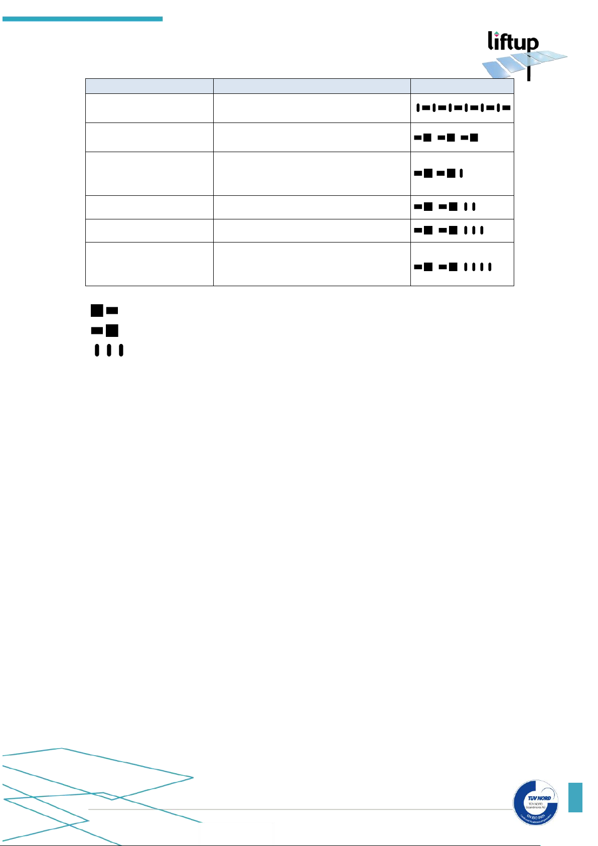
Speak
Activity/warning
Warning
– automatic operation
A warning that the lift has to become a
staircase
BEEP-BEEP-BEEP…
The lift is in the process of becoming a
staircase
…
Emergency stop pressed
The red emergency stop button has been
pressed in. This must be released in order
that the lift can function again
The lift is locked
The lift is locked with a key switch
Battery warning
Low battery level
Power supply is
interrupted – connect or
press emergency stop
Connect to a power supply or activate
emergency stop in order to power off the
lift
High tone followed a deeper tone
Low tone followed by higher tone
Identical tones (3 off)
Page 25

USER MANUAL – FLEXSTEP V2 – US VERSION 1.3
Liftup Inc. | 4809 Ehrlich Road | Suite 105 | FL – 33624, Tampa | T: +1 844 543 8878 | M: [email protected] | www.liftup.us
25
11. Operability
Under normal operating conditions the lift shall always be connected to an electrical outlet
socket. It is very important that the power is not disconnected or switched off as long-standing
power outage (10-20 hours) may result in discharged batteries and thus inoperability in which
case the lift cannot be used until the batteries have been recharged. An audible alarm will sound
if the power supply is interrupted (please see section 10.8).
11.1 Battery backup
In the event of power failure or if power to the control system gets disconnected for some
other reason, the system will automatically switch to backup mode. This means that the system
will continue to work, as the lift will then be powered by a backup battery. An audible alarm will
sound in the event of power failure. The alarm will cease as soon as power is returned to the
lift, and the system returns to normal operating mode. However, should it not be possible to
immediately supply power and you wish to stop the alarm, press the emergency stop. (Be aware
that the system will now need calibrating – please see below).
IMPORTANT! If the electrical power outlet has been disconnected and the
emergency stop activated at the same time, the system will automatically switch
to “safety mode” and will then need calibrating. (Please see below).
11.2 Calibration following emergency stop/power failure
The lift will require calibration if the emergency stop has been activated and the power supply
interrupted, or if the system registers some other type of irregularity. The lift automatically goes
into a special “safety mode” which only permits slow speed downward movement.
IMPORTANT! If you notice the lift not working as expected or if it stops after
only a few inches, technical problems may have arisen which require attention by
technically qualified personnel. Contact your dealer for further assistance.
Page 26
USER MANUAL – FLEXSTEP V2 – US VERSION 1.3
Liftup Inc. | 4809 Ehrlich Road | Suite 105 | FL – 33624, Tampa | T: +1 844 543 8878 | M: [email protected] | www.liftup.us
26
12. Maintenance
Clean the lift by wiping with a well-wrung cloth using water mixed with a mild detergent.
IMPORTANT: Do NOT use a high-pressure jet or rinse the lift directly using a
hose. Do not use aggressive cleaning agents or similar on the lift, and avoid salt or
sand coming into contact with the lift in connection with winter maintenance.
Any oiled wooden surfaces are to be regularly maintained (approx. every 3 months) with wood
oil in order to ensure wood service life. Varnish according to need.
Check beneath the lift regularly for any leaves, branches or other objects and remove these in
order to ensure free movement.
The mechanical maintenance of the lift shall normally only be undertaken in connection with the
regular service inspections. These are to be performed by an authorised service technician.
Should unexpected errors or jarring sounds occur, contact your dealer at once.
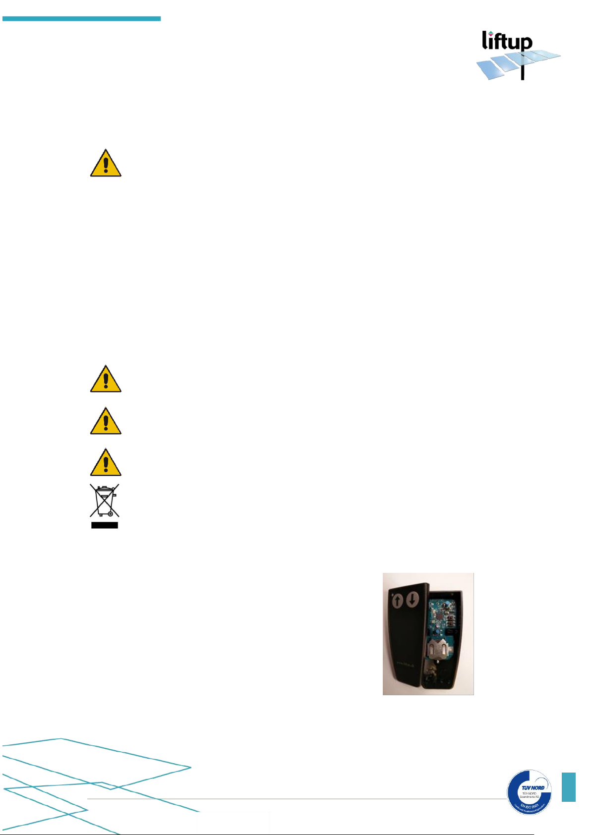
Remote controls (supplementary equipment)
A CR2032 battery is installed in the remote controls.
In order to ensure reliable function, swap the batteries every 2 years
DO NOT swallow coin cell batteries
Keep batteries out of reach of small children. Should a child swallow a
battery, consult a physician immediately
DO NOT put the battery in trash. When disposing, comply with local
ordinances or regulations
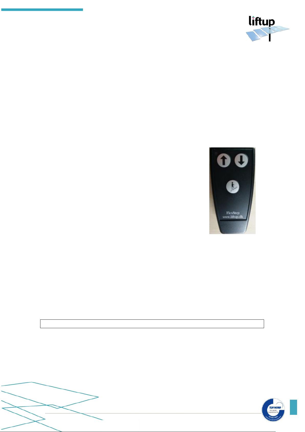
To swap the battery, do the following:
Handheld Remote
1. Loosen the screw on the rear of the remote control
2. Remove the back panel
3. Swap the battery
4. Refit the back panel and test
Page 27
USER MANUAL – FLEXSTEP V2 – US VERSION 1.3
Liftup Inc. | 4809 Ehrlich Road | Suite 105 | FL – 33624, Tampa | T: +1 844 543 8878 | M: [email protected] | www.liftup.us
27
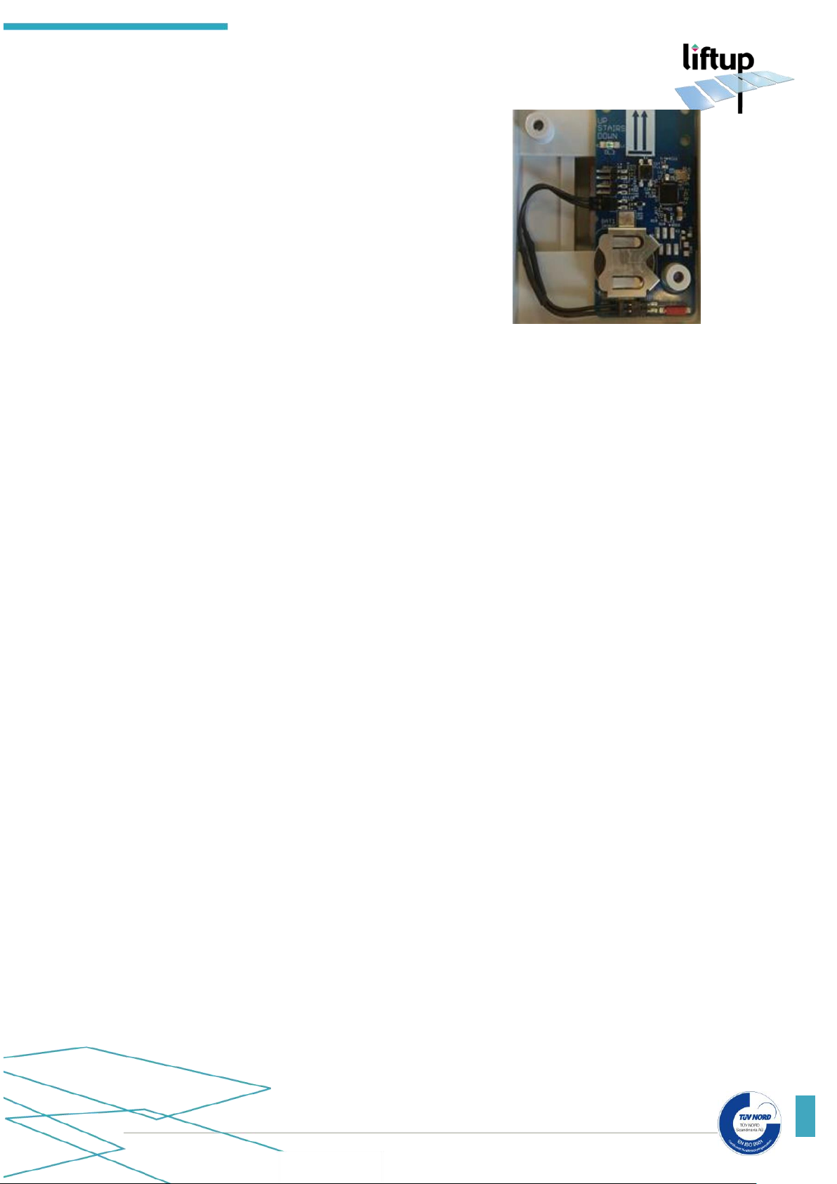
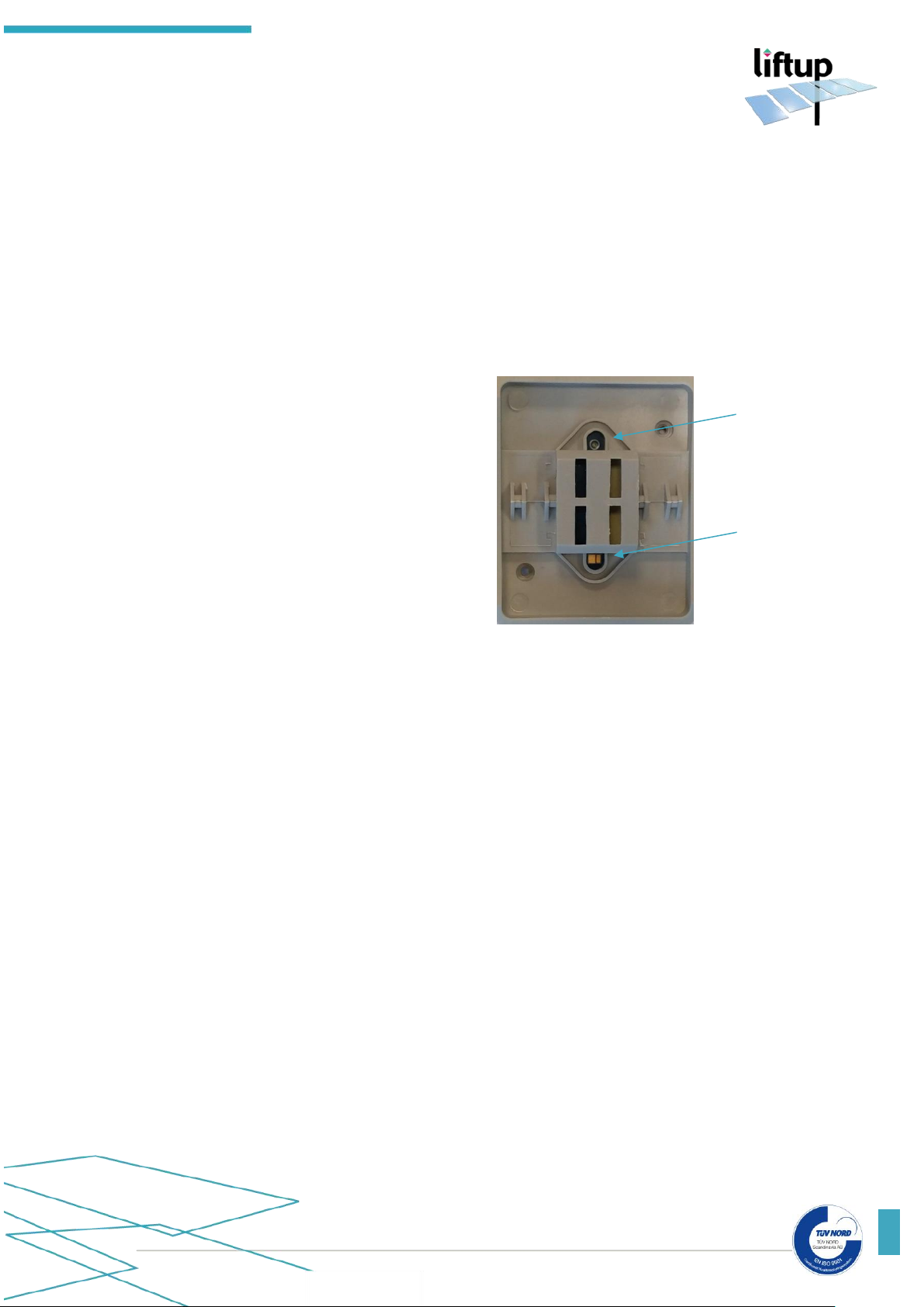
Wall Mounted Remote
1. Remove the black Push button front, loosen the 2
screws (PH1), on the rear of the grey part, where the
PCB with the battery is mounted
2. Swap the battery
3. Refit the parts and test
Page 28
USER MANUAL – FLEXSTEP V2 – US VERSION 1.3
Liftup Inc. | 4809 Ehrlich Road | Suite 105 | FL – 33624, Tampa | T: +1 844 543 8878 | M: [email protected] | www.liftup.us
28
13. How to pair the transmitter and receiver
13.1 Remote control and receiver
The transmitter and receiver must always be paired in order to work. The receiver will not
react to a transmitter which is not paired with it. A receiver can be paired with up to 20
transmitters. A transmitter can be paired with several receivers if required. When a receiver is
powered on (please see section 10.7) the RF-Status in the connection box will flash for 2
minutes. Or until it is paired with a transmitter.
How to pair the transmitter and receiver
How to reset the transmitter and receiver
To reset a remote control so that it is no longer paired, do as follows:
• Press the UP (↑) and DOWN (↓) buttons at the same time and hold them down for approx.
5 seconds until the control LED on the remote control begins to flash slowly.
• The remote control is now in installation mode for 2 minutes.
• Perform the following within the 2 minutes:
Press: UP(↑), UP(↑), DOWN(↓), DOWN(↓), UP(↑), DOWN(↓), UP(↑), DOWN(↓)
How to reset the receiver
• Switch the receiver on.
• Short-circuit JP1-1on the connection box board.
• When the control LED begins to flash rapidly, the receiver has been reset.
• Should the control LED not flash rapidly, this means that no receiver has been paired.
1. Ensure that there is power to the system. Press the
emergency stop and switch off the on/off switch on the side
of the lift (please see section 10.7).
2. Press the UP (↑) and DOWN (↓) buttons on the remote
control at the same time and hold them down for approx.
5 seconds until the control LED on the remote control
begins to flash slowly. The remote control is now in
installation mode for 2 minutes.
3. Within these 2 minutes, release the red emergency stop
on the lift by turning it clockwise.
4. When the control LED on the remote control stops
flashing, it is paired with the lift.
5. Test the system so as to ensure the pairing has been
performed correctly; if not, repeat 1-5 above.
6. If you need to pair several remote controls to the receiver,
repeat step 2. above.
7. Switch on the on/off switch on the side of the lift.
Page 29
USER MANUAL – FLEXSTEP V2 – US VERSION 1.3
Liftup Inc. | 4809 Ehrlich Road | Suite 105 | FL – 33624, Tampa | T: +1 844 543 8878 | M: [email protected] | www.liftup.us
29
13.2 Wireless call station and receiver
The transmitter and receiver must always be paired in order to work. The receiver will not
react to a transmitter which is not paired with it. A receiver can be paired with up to 20
transmitters. A transmitter can be paired with several receivers, if required. When a receiver is
powered on (please see section 10.7) the RF-Status in the connection box will flash for 2
minutes. Or until it is paired with a transmitter.
How to pair the transmitter and receiver
1.
The receiver, i.e. FlexStep must be switched off. The lift is switched on/off by activating
both the ON/OFF switch and the emergency stop.
2. Remove the front pushbutton and use a
small screwdriver to short-circuit the SJ2
on the remote control* until the control
LED on the remote control* begins to flash
slowly.
(If not mounted, press the S4 button which
has the same function).
3.
The remote control* is now in installation mode for 2 minutes.
4.
Within these 2 minutes, switch on the lift i.e. the FlexStep.
5.
The control LED on the remote control* is associated with the lift when it stops flashing.
Test the system, to ensure the pairing has been performed correctly; if not, repeat steps 1.-5.
above.
*Supplementary equipment
How to reset the transmitter and receiver
To reset a call station so that it is no longer paired with a particular lift, do as follows:
• Set dip switch S4 #1 to ON and press on the contact or connect (↑) or (↓) using a metal
object. The control LED on the call station will flash rapidly.
• The pairing with the receiver has now been erased.
• Return dip switch S4 #1 to off.
How to reset the receiver
• Switch the receiver on.
• Short-circuit JP1-1on the connection box board.
• When the control LED begins to flash rapidly, the receiver has been reset.
• Should the control LED not flash rapidly, this means that no receiver has been paired.
LED
SJ2
Page 30
USER MANUAL – FLEXSTEP V2 – US VERSION 1.3
Liftup Inc. | 4809 Ehrlich Road | Suite 105 | FL – 33624, Tampa | T: +1 844 543 8878 | M: [email protected] | www.liftup.us
30
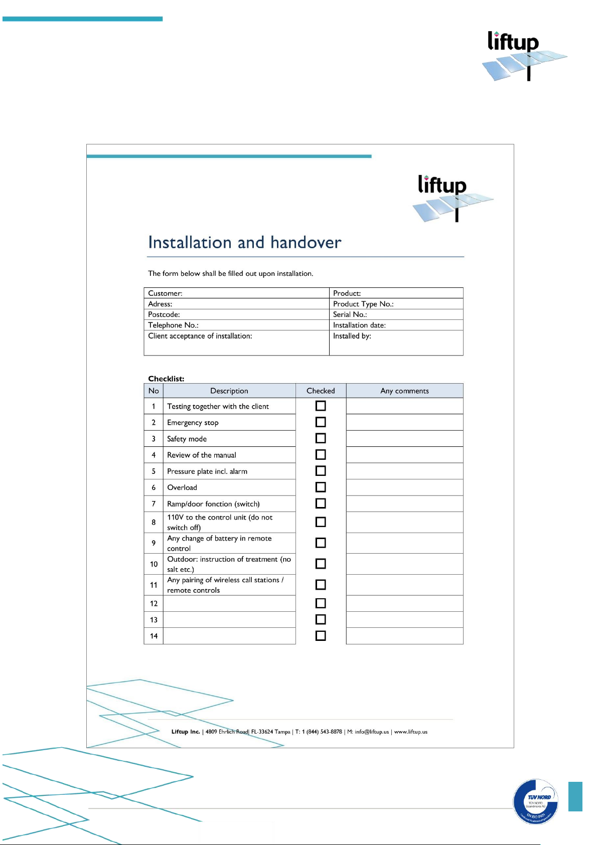
14. Installation and handover form
The form below shall be filled out upon installation.
Page 31

USER MANUAL – FLEXSTEP V2 – US VERSION 1.3
Liftup Inc. | 4809 Ehrlich Road | Suite 105 | FL – 33624, Tampa | T: +1 844 543 8878 | M: [email protected] | www.liftup.us
31
15. Maintenance checklist
In addition to the general maintenance described in section 12, we recommend as the
manufacturer, that routine inspections are undertaken at least every 6 months by an authorised
service technician. The dealer you have bought the product from will offer this service, but if
you wish to use another service provider, the owner of the lift is responsible for ensuring that
the chosen service technician is qualified in the product in question.
(Please also see: http://www.liftup.dk/en/distributors/ if necessary).
For safety reasons it is very important that these inspections are maintained, since lacking or
improperly performed inspections may result in personal injury.
IMPORTANT! Before servicing the lift, the emergency stop button must be
activated. This is to prevent accidental operation. It is the responsibility of the
service technician to operate the emergency stop before servicing work is begun.
NB. It is not enough to disconnect the power supply, as the system is fitted with
a battery backup.
Page 32
USER MANUAL – FLEXSTEP V2 – US VERSION 1.3
Liftup Inc. | 4809 Ehrlich Road | Suite 105 | FL – 33624, Tampa | T: +1 844 543 8878 | M: [email protected] | www.liftup.us
32
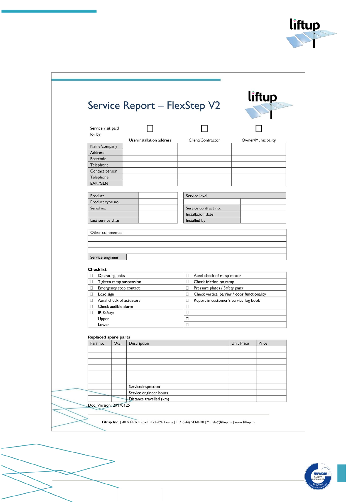
A check form like the one below shall be filled out at each inspection. The form shall be filed by
the company which has entered into the service agreement.
Page 33
USER MANUAL – FLEXSTEP V2 – US VERSION 1.3
Liftup Inc. | 4809 Ehrlich Road | Suite 105 | FL – 33624, Tampa | T: +1 844 543 8878 | M: [email protected] | www.liftup.us
33
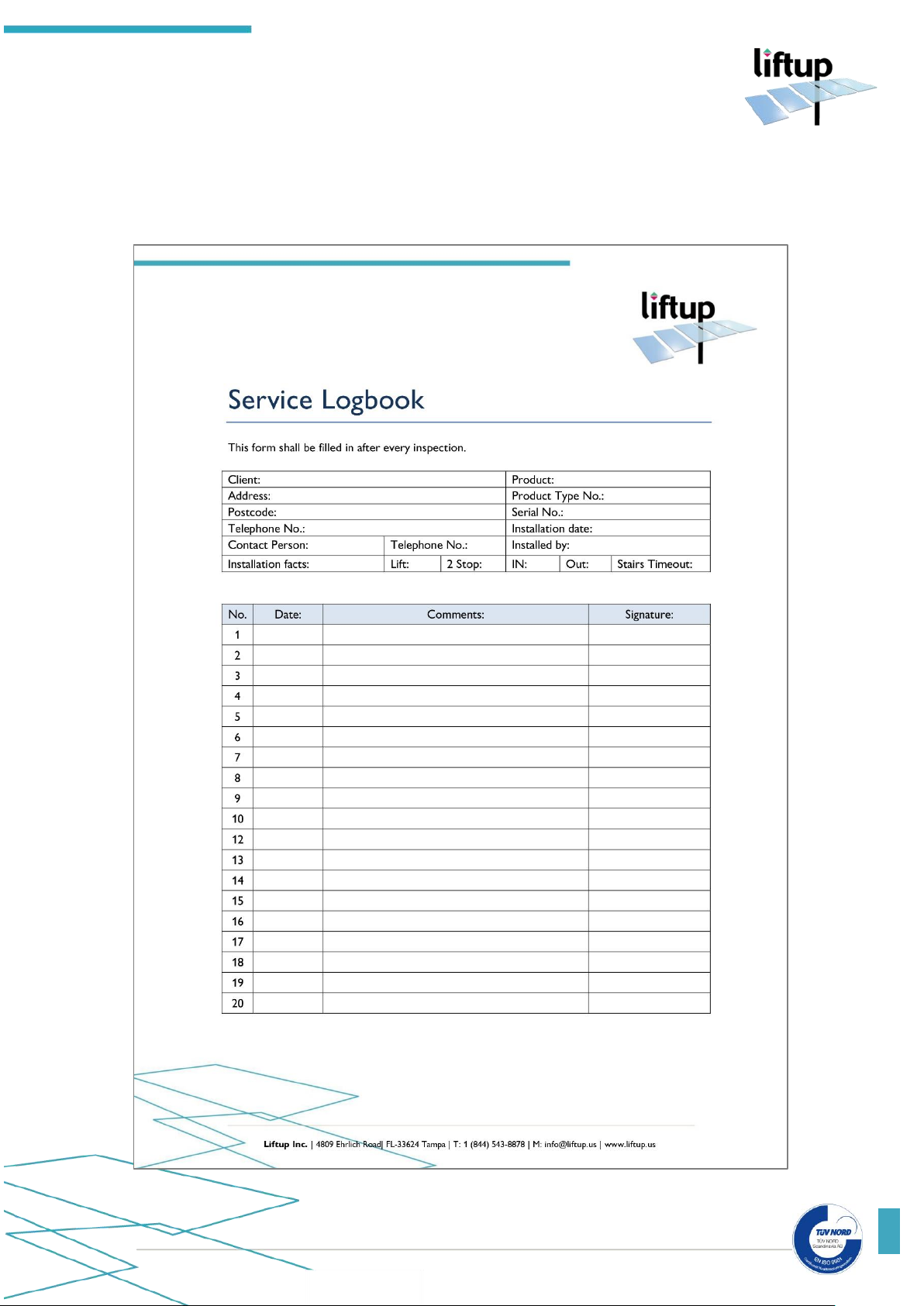
16. Service logbook
The service logbook form shall be filled out after each inspection. The logbook shall be kept
together with the lift.
Page 34
USER MANUAL – FLEXSTEP V2 – US VERSION 1.3
Liftup Inc. | 4809 Ehrlich Road | Suite 105 | FL – 33624, Tampa | T: +1 844 543 8878 | M: [email protected] | www.liftup.us
34
17. Spare parts and accessories
It is important to use only original spare parts and accessories. Replacement of parts may only
be undertaken by a qualified service technician.
The use of non-original spare parts may void the factory warranty. Furthermore, product safety
may be compromised, which may pose a risk to personal safety.
Spare part no.
Description
103332
Spare part package - FlexStep V2
100338
Micro Switch - Safety system - V4L IP67
100339
Emergency Stop Button
100413
Spring for ramp lock.
101139
Timing belt
102352
Control Board for FlexStep V2
102726
Print for connection box FS V2/EL X
102744
Motor for barrier, FS2
102759
POM guide for stairs/wall profile
102766
Brush for wall profile
102768
Spring for safety barrier contact
102769
Print for safety barrier contact
102890
Battery 12V 5Ah LiFePo4 Raizer / FlexStep V2
103008
IR Safety RX board - FlexStep V2
103009
IR Safety TX board - FlexStep V2
103011
IR Termination board - FlexStep V2
103033
Plastic washer for steps, FS2
103080
Power supply unit 36 V
103090
Circlip for steps, FS2
103091
E-chain for FS2
103092
Mounting bracket for E-chain
103094
Motor for ramp FS2
103108
Complete spindle unit with motor
103289
Push button, FS2, arrow, outdoor
103290
Push button, FS2, bell, outdoor
103333
Programming Cable FS2
Page 35

USER MANUAL – FLEXSTEP V2 – US VERSION 1.3
Liftup Inc. | 4809 Ehrlich Road | Suite 105 | FL – 33624, Tampa | T: +1 844 543 8878 | M: [email protected] | www.liftup.us
35
18. Disassembly
In order to ensure correct disassembly for any re-use in another installation, we recommend
using an authorised service technician. Contact your dealer for assistance with disassembly.
Bear in mind that there may be a risk of overturning when FlexStep V2 is detached
from the building structure.
19. Disposal
It is the duty of the owner to dispose of the product in accordance with the regulations
applicable at the time. Please note that the control unit and remote control contain batteries,
which must be disposed of separately.
Do not dispose of batteries or electrical or electronic equipment with unsorted household
rubbish. When disposing of this device, ensure compliance with local ordinances and regulations.
Consider contacting your dealer for assistance with disposal.
20. Right of complaint
The right of complaint encompasses the at any time applicable rules regarding the right of
complaint. Please read more about this in the terms of sale and delivery:
https://www.liftup.us/about-liftup-inc/general-conditions/
IMPORTANT! If the prescribed service inspections are not maintained, the right
of complaint may be lost. Failing to perform these inspections can also have serious
consequences for product safety. It rests with the customer to ensure compliance
with the prescribed service inspections at all times.
Enjoy using your new FlexStep V2!
Best regards,
Liftup Inc.
Page 36

USER MANUAL – FLEXSTEP V2 – US VERSION 1.3
Liftup Inc. | 4809 Ehrlich Road | Suite 105 | FL – 33624, Tampa | T: +1 844 543 8878 | M: info@liftup.us | www.liftup.us
36
 Loading...