

LIFT-O-FLEX 19500S User Manual

R ON I
8001 Tower Point Drive
Charloe, NC 28227 USA
+1 866 543 8635
+1 704 847 2464
LIFT-O-FLEX
19500S
LIFTER
USER MANUAL
DOCUMENT ID: 01022018
PLACE
SERIAL
NUMBER
LABEL
HERE
Have Quesons?
We’re here for you.
info@roni.com
www.roni.com

BEFORE YOU BEGIN
▪▪▪
READ
It is important that you read and understand this complete manual prior
to using your LIFT-O-FLEX® ergonomic handling equipment. If you have any
questions, contact your dealer or RonI.
+1 866 543 8635
+1 704 847 2464
info@roni.com
www.roni.com
8001 Tower Point Drive
Charlo�e, NC 28227 USA
SPECIAL NOTES
The appearance of your LIFT-O-FLEX® lifter and the accompanying attachments
may differ from the images displayed in this manual due to the custom nature
of this equipment.
LIFT-O-FLEX® is a registered trademark of RonI, Charlotte, North Carolina.
Where Ergonomics make
Economic sense.

TABLE OF CONTENTS
1. DESCRIPTION
1.1 OVERVIEW
1.2 OPTIONS
1.3 ATTACHMENTS
2. SAFETY 5
2.1 BUILT-IN SAFETY FEATURES
2.2 STORAGE AND TRANSPORT
2.3 MOVEMENT
2.4 LOADING AND UNLOADING
3. WARRANTY
4. ASSEMBLY INSTRUCTIONS
4.1 ASSEMBLY
4.2 DISASSEMBLY
5. OPERATING INSTRUCTIONS
5.1 USING THE LIFTER
5.2 ADJUSTING THE HANDLEBAR
5.3 POWER PACK
5.4 REMOTE CONTROL
5.5 BRAKE SYSTEM
13
4
6
8
6. MAINTENANCE
6.1 GUIDELINES
6.2 EVERYDAY
6.3 EVERY YEAR, OR WHEN NEEDED
7. TROUBLESHOOTING
8. TECHNICAL SPECIFICATIONS
9. SCHEMATICS
9.1 WIRING DIAGRAM
9.2 SPARE PARTS
10. DECLARATION OF CONFORMITY
info@roni.com
www.roni.com
+1 866 543 8635
+1 704 847 2464
L
IF T-O -
8001 Tower Point Drive
Charlo�e, NC 28227 USA
F LEX 19500S
15
19
20
21
31
| 3

1. DESCRIPTION
1.1 OVERVIEW
LIFT-O-FLEX® lifters are ergonomically designed to simplify handling, lifting, and transportation of
goods. Each lifting unit can be equipped with different types of load carriers or attachments. The
goods to be handled are placed on the load carrier and adjusted to the desired height
by pressing the buttons on the hand-held remote control pendant. The lifter is powered by
rechargeable, sealed, lead acid batteries. The lift mast is totally enclosed and features a ball screw
for smooth vertical DC-powered movement.
1.2 OPTIONS
The LIFT-O-FLEX comes standard with a Powder-Coated Paint/Anodized finish. As an additional
option, the LIFT-O-FLEX is also available in Stainless Steel/Anodized finish.
An additional electronic power pack with quick exchange features is available to allow for multishift
use.
1.3 ATTACHMENTS
Standard attachments for the LIFT-O-FLEX include a load platform, with or without a stationary or
rotating V-Block, a fixed core probe, an Expand-O-Turn, and Squeeze-O-Turn. Custom applications
are also available upon request.
Platform with V-Block
Core Probe
Expand-O-Turn
4 | USER MANUA L
8001 Tower Point Drive
Charlo�e, NC 28227 USA
Squeeze-O-Turn
+1 866 543 8635
+1 704 847 2464
DO C UMENT I D: 01022018
www.roni.com
info@roni.com

2. SAFETY
2.1 BUILT-IN FEATURES
The ergonomic design of the LIFT-O-FLEX is, in itself, an active factor of operational safety. The
rear casters are equipped with pedal-activated brakes and the handle bar adjusts vertically to
provide optimal ergonomic positioning for the operator. The lift mast contains a slip clutch; if
anything gets in the way of the downward movement of the attachment, the slip clutch engages
to help prevent injuries as well as mechanical damage to the lifter. We have also incorporated
current limiting to prevent overloading beyond the rated capacity for the unit.
2.2 STORAGE AND TRANSPORT
During storage and transport, the remote control pendant and motor cable should be
disconnected. The lifter should be secured during transport to avoid the risk of tipping over.
2.3 MOVEMENT
The load carrier should always be lowered as low as possible to ensure safe and stable
handling. Use caution when passing thresholds, cords, and other objects on the floor. The
handle bar should be gripped in a way so that the hands are not hurt when passing edges,
walls, or protruding objects. The movement of heavy loads can be easier when using the
directional lock (details listed under 5.5 Brake System).
2.4 LOADING AND UNLOADING
The user is responsible for ensuring that the lifter is loaded correctly.
Always apply the brakes when loading and unloading.
The center of gravity of the goods should always be centered on the load carrier and positioned
as close to the lift mast as possible for maximum stability.
The load carrier should be positioned at the correct height before loading and unloading
to allow a good working position. The load should be pushed or pulled on or off of the load
carrier.
info@roni.com
www.roni.com
+1 866 543 8635
+1 704 847 2464
L
IF T-O -
8001 Tower Point Drive
Charlo�e, NC 28227 USA
F L
E X 19500S
| 5

3. WARRANTY
Limited Warranty
RonI warrants this product to be free of defects in material and workmanship during the
warranty period. Our warranty obligation is to provide a replacement for a defective original
part if the part is covered by the warranty, after we receive a proper request from the warran-
tee (you) for warranty service.
Who may request service?
Only a warrantee may request service. You are the warrantee if you purchased the product
from RonI or from an authorized distributor and RonI has been fully paid.
What is an “original part”?
An original part is a part used to make the product as shipped to the warrantee.
What is a “proper request”?
A request for warranty service is proper if RonI receives: 1) a photocopy of the customer
invoice that displays the shipping date and 2) a written request for warranty service that
includes your name and phone number. Requests may be sent using the following methods:
Mail
RonI
8001 Tower Point Drive
Charlotte, NC 28227
Fax
Toll Free 1-866-543-9532
Direct 1-704-847-6739
Email
info@roni.com
What is covered under the warranty?
After RonI receives your request for warranty service, an authorized representative will contact
you to determine whether your claim is covered by the warranty. Before providing warranty
service, RonI may require you to send the entire product, or just the defective part(s), to its
facility in Charlotte, North Carolina.
How long is the warranty period?
The warranty period for original dynamic components is one (1) year. For batteries, the
warranty period is 30 days. The warranty period begins on the date when RonI ships the
product to the warrantee.
6 | USER MANUA L
8001 Tower Point Drive
Charlo�e, NC 28227 USA
+1 866 543 8635
+1 704 847 2464
DO C UMENT I D: 01022018
www.roni.com
info@roni.com

Warranty Evaluation
All parts sent back (freight paid by customer) to RonI for warranty replacement and/or repair
will be evaluated. RonI will determine if the part is a warranty issue or if it has been damaged
due to misuse or negligence. A written report will be issued detailing the investigation of the
part and whether or not the part is classifed as warranty.
What is not covered by this warranty?
1. Labor
2. Freight
3. Occurrence of any of the following, which will automatically void the warranty:
• product misuse
• negligent operation or repair
• corrosion or use in corrosive environments
• inadequate or improper maintenance
• damage sustained during shipping
• collisions or other incidental contacts causing damage to the product
• unauthorized modifications: do not modify the product in any way without first
receiving written authorization from RonI as modifications(s) might make the
product unsafe to use or could potentially cause excessive and/or abnormal wear
If a defective part is warranteed, how will RonI correct the problem?
RonI, will provide an appropriate replacement for any covered part. An authorized repre-
sentative of RonI will contact you to discuss your claim.
Warranty Procedure
In the event that a part is damaged or broken,
please contact RonI via phone or email to establish
a dialogue to identify and diagnose the problem.
Please have your lifter serial number available
when you call or email.
(located on the motor cover underneath the
intermediate)
info@roni.com
www.roni.com
+1 866 543 8635
+1 704 847 2464
L I F T- O-F L EX 19500S | 7
8001 Tower Point Drive
Charlo�e, NC 28227 USA

4... ASSEMBLY INSTRUCTIONS
The wheel frame and the cross-member are integrated on some models:
Lifter leg
Power pack
Remote control
8 | USER MANUAL
8001 Tower Point Drive
Charlo�e, NC 28227 USA
Intermediate
Handlebar
Charger
+1 866 543 8635
+1 704 847 2464
Lift mast
End-effector
DO C UMENT I D: 01022018
www.roni.com
info@roni.com

4.1 ASSEMBLY
Assembly Instructions
The lifter is normally delivered disassembled in modules or partially assembled in order to minimize freight
costs. When the lifter is delivered disassembled, each module comes separate with required screws and
tools, etc. When the lifting device is delivered partially assembled, the frame will be together and the
components such as masts, power pack and handle will need to be mounted to the frame.
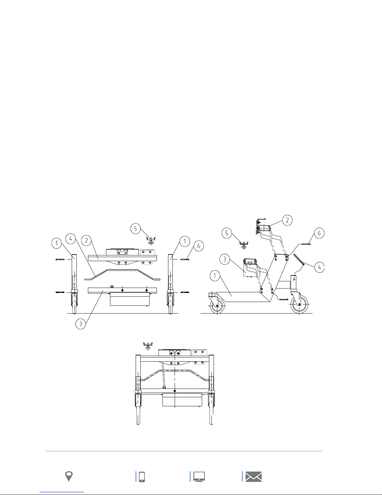
ASSEMBLING THE FRAME
(Associated diagrams on the next page)
Tools: 1 Allen wrench key size 5mm
Bolts: 16pc. M8x70 mm (6)
Modules: 1 pair of legs (1), 1 pc. Upper intermediate section (2), 1pc. Lower intermediate section (3), 1 pc
Brake rod (4), 1 pc. Lock for Power Pack (5), (needed when power pack is to be mounted),
1)
Before assembling the frame, the rear casters on each leg (three position-see example on next page);
should be locked in the directional lock mode. This is accomplished with the brake rod (4). Insert
one end of the rod into the hole located on the caster holder and turn it so the wheel is
directionally locked and is in the proper position. (Do this on both legs).
2)
Place the upper intermediate section (2) and the lower intermediate section (3) on edge. The upper
intermediate section has the mast slide located on the center and should be placed facing the front
casters. The lower intermediate section has the lift motor attached and should be placed so that the
(2) screws that attach the lift mast to the lower intermediate section face the front casters. Take one
of the legs (1) (the hex hole for the brake rod should face down) and mount it with the enclosed bolts
(6) 8 pcs. Screw it in place (do not tighten). Turn the intermediate sections with one leg attached over
and mount the opposite leg. Insert the brake rod (4) into the hex holes in the proper position before
attaching the leg with the bolts. (do not tighten). The brake rod (4) should be pointed up and
perpendicular to the legs.
Place the frame on its wheels on a level floor. Put pressure on the legs so that each wheel has contact
3)
with the floor. Now, tighten all the bolts in place.
info@roni.com
www.roni.com
+1 866 543 8635
+1 704 847 2464
I F T- O-F L EX 19500S |
L
8001 Tower Point Drive
Charlo�e, NC 28227 USA
9
B ROD POSITIONS
Free Wheeling
Set Brake
Directional Lock
10 | USER MANUA L
8001 Tower Point Drive
Charlo�e, NC 28227 USA
+1 866 543 8635
+1 704 847 2464
DO C UMENT I D: 01022018
www.roni.com
info@roni.com

ASSEMBLING THE END EFFECTOR AND MAST
(Associated diagrams on the next page)
Tool: 1 pc. Allen wrench size 5 mm, 1 pc. regular wrench size 13 mm
Screw: The bolt holding the mast: each bolt and nut is on the frame, the platform screw 2 pcs. 3/8”x 3 ½”
Modules: 1 pc. mast (7), 1 pc. Load platform (8), 1 pc. slave mast (12)
Remove the 3 screws (9) which are on the lower intermediate section and loosen the 4 nuts (10)
1)
on both sides of the intermediate section.
Make sure the yellow plastic coupling on the motor is still in place on the gear reducer.
2)
Rotate the primary mast so the coupling is pointing down. Move the mast slide all the way to its bottom
3)
position. Note: The slide can travel down at a high rate of speed should it be on the opposite end when
rotating the mast for placement! The slide should be in the lowest position when mounting the mast.
4)
Insert the mast over the guide rails on the upper intermediate section and push the mast down in order
for the fastening plate to cover the lower intermediate section. Make sure the coupling on the lift mast
and motor are properly mated together or the lower bolts cannot be installed. Installing the slave mast is
the same as the primary except for aligning coupling to lift motor which is not required. Also, attach the
top mast bracket prior to installing end-effector.
Fasten the first 3 bolts (9), this will automatically center the mast. Next, tighten the 4 bolts (10) on the
5)
guide rails in the upper intermediate section.
The end-effector can now be mounted with its 2 bolts (11).
6)
Should you have an accessory which requires electricity this is to be connected to the power pack (5) into
7)
the same outlet as the battery charger. While charging, these accessories will have to be disconnected.
After charging remember to reconnect the plug for the accessory.
info@roni.com
www.roni.com
L I F T - O-F L EX 19500S | 11
+1 866 543 8635
+1 704 847 2464
8001 Tower Point Drive
Charlo�e, NC 28227 USA
 Loading...