


Manual
F5021B
Lift controller 32 bit system
version E02.2(MA)

Directory
Table of Contents
1. F5021 Mainboard..........................................................................................1
Product characteristics.......................................................................1
Scope of operation...............................................................................1
2.System overview..............................................................................................3
Main module SM01.............................................................................3
Car module SM02................................................................................3
Command Modue SM03.....................................................................3
Floor module SM04.............................................................................3
Special module SM09..........................................................................4
funktional overview.............................................................................4
3. Operation equipment....................................................................................7
Operation of the system:.....................................................................8
Log - in:................................................................................................8
Menu.....................................................................................................8
Window with status in the submenu „Monitor“..............................8
Adjusting Parameters in submenu Para.Select................................9
different functions (Func.Select)......................................................11
4.Menu tree & parameter...............................................................................13
Basic parameters (Main Para.)........................................................14
Inspection parameter (Insp.Option)................................................14
Driving cycle parameter (S-Curve).................................................14
Multistep-parameter (Multi Speed).................................................15
Door parameter (Door Control).......................................................16
Adjusting floor display (Flr.Disp.)...................................................17
Enabling floors (Service Flr.)...........................................................18
Blocking florrs (Floor Block)...........................................................18
Defining coercive stop (Comp. Stp.)................................................18
Defining the building fill-up/dump (Heavy Traf.)..........................18
5.Shaft copy......................................................................................................21
re-levelling sensor:.............................................................................22
Contactor:..........................................................................................22
Adjusting switch................................................................................22
Inspection end switch........................................................................22
Intelligent magnetic sensor iMS45...................................................23
Design and functionality...................................................................23
Assembly diagram iMS45_POS.......................................................24
Assembly diagram iMS45_SPD (only for controller without a
machine room)...................................................................................24
6.SM01 F5021 main board..............................................................................25

Directory
SM01 circuit points:..........................................................................25
7.SM02/SM03 carmodule................................................................................29
reference note:...................................................................................29
SM02 circuit Points...........................................................................29
SM03 Push button module...............................................................31
8.SM02/H Controlcabinet module.................................................................33
9.SM09IO/B Expansion board.......................................................................35
10.SM02/G Car box module...........................................................................37
11.SM04HRF floor module.............................................................................39
12.Security........................................................................................................41
Security circle....................................................................................41
optional security switches.................................................................41
circuit of security...............................................................................42
Components.......................................................................................42
Functionality:.....................................................................................43
Possible sources of error:..................................................................43
Additional controll by the controller...............................................43
Scan-circuit of the security circle.....................................................43
N-type.................................................................................................44
Checking:...........................................................................................44
Relay for precontrolling....................................................................44
Trip monitoring.................................................................................44
Checking:...........................................................................................44
Complementary notes for inspection:.............................................44
Generally:...........................................................................................45
Isolation reading:...............................................................................45
13.Triggering of the frequency inverter........................................................47
Generally............................................................................................47
Triggering Multistep binary.............................................................47
Driving cycle......................................................................................48
speed and distances for brake..........................................................48
14.List of parameter........................................................................................49
15.Error codes..................................................................................................59

Manual F5021B - F5021 Main board
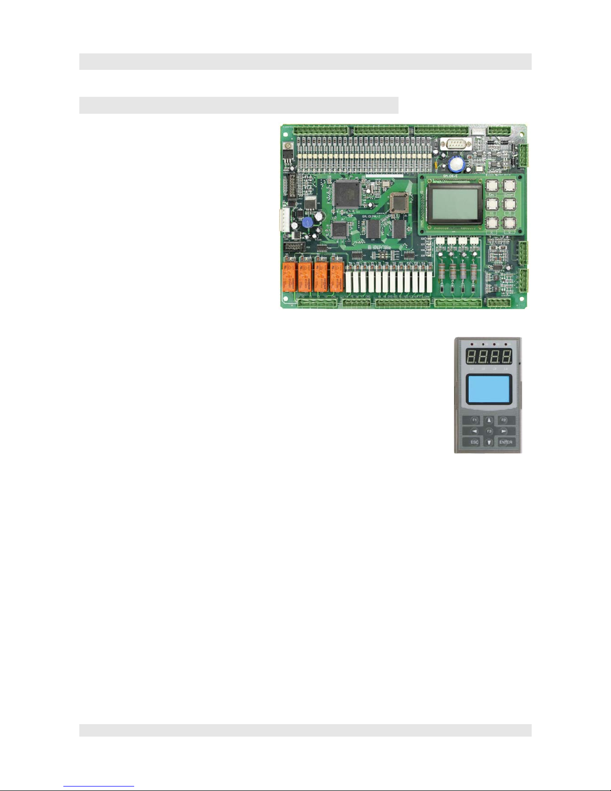
1. F5021 Main board
Product characteristics
• 32bit processor ARM7 industrial
standard
• Doubble-processor-architektur for
extended security needs
• 2x CAN interfaces separate for internal
and external communication
• high EMV-stability (EFT-4000V)
• high ESD- stability (ESD 8000V)
• certified for EN81, GB7588, CE
Functionallity area
• For rope- and hydraulik-lifts
• A lot of functions possible to parametize for nearly all kinds of lifts.
• Lifts from 0,63m/s to 4m/s.
• Up to 64stops, also with selective door controlling
• Replace the 16bit-board F2021 (longtime supply with replacement parts is secured)
• Analoge or digital triggering of the frequency inverter respectively chopper.
• Shaftdetection via incremental shaft encoder (RS422, HTL, SSI)
• Duplex groupe function integrated, possible to exted up to group times 8
• Weight compensation at start-up with according weight measuring system.
• ID-card system (credit card -transponder) possible to integrate.
• Remote control locally and globally
• Graphical LCD direct on board or a separate controller.
• Description of Drive cycle, on- and off- activities, status information etc.
• Error information memory (20 digits) with real-time coverage and full text advice.
• As standard are 2 cabine doors, possible to expand for 3 doors.
• Lot of special features, e.g. automatical evacuation with choose of direction conditioned to the weight.
Page 1

Manual F5021B - System overview
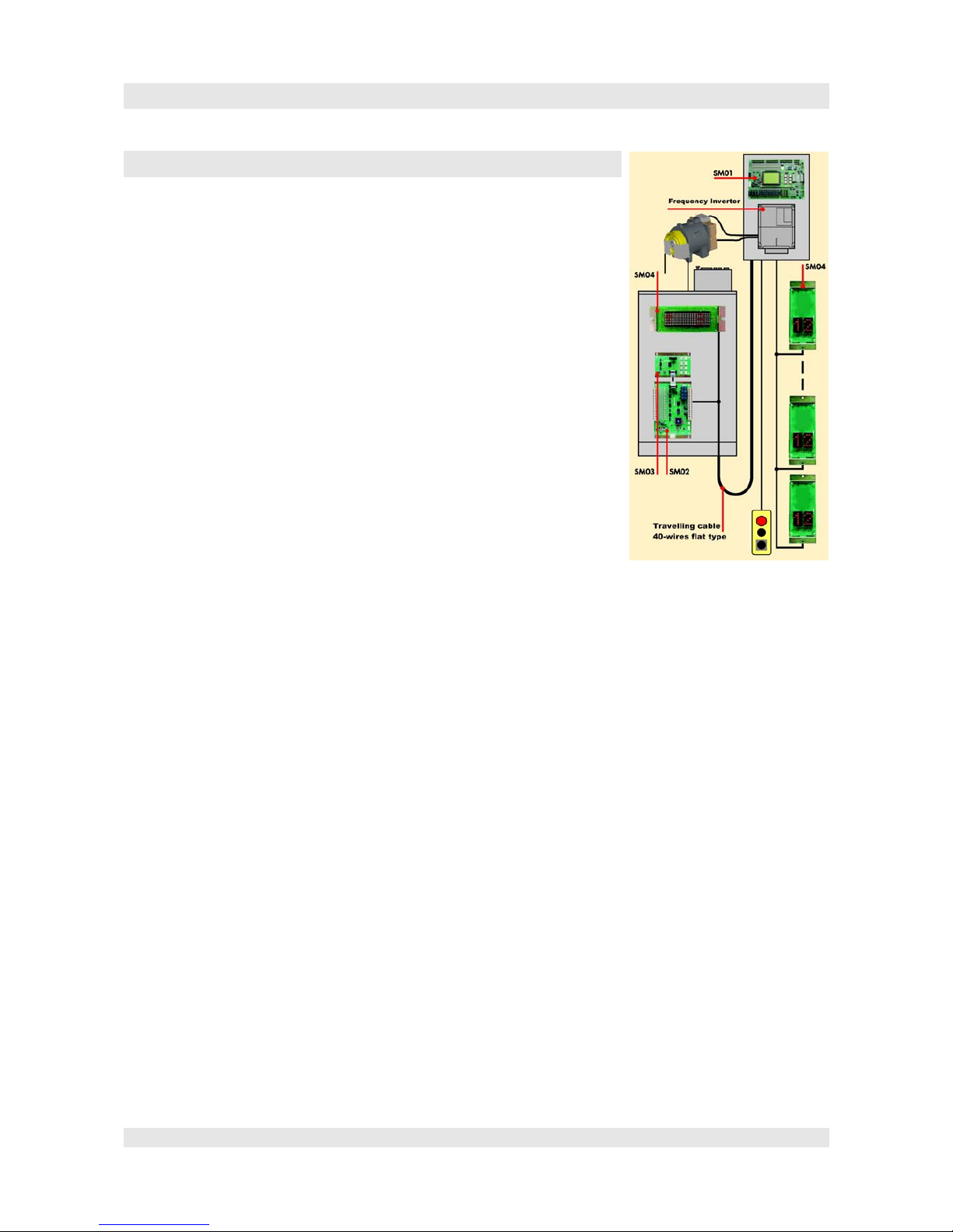
2.System overview
SmartCom is a modern, based on newest technology controller
system, especially for elevators.
The system basically composed of following components:
• Main module SM01
• Car module SM02
• Command-module SM03
• Floor module SM04
• Expansion module SM09
Different variations of the serveral modules make the best and
optimized adjustment of the controller system possible for the
respective lift and the requested functionallity area.
Based on the never changing CAN-journal its possible to realize
controller for simple and complex lifts.
All components are, due to the CAN-systems, nearly in any order
possible to be combined, and after all possible to be extended.
Main module SM01
The main module is in the Controlcabinet and is the heart of the
controller. It contains all functions, especially trigging the handler,
recognitize the possition of the lift and lots of special features, which are normally directed to the
shaft and the engine room. It is communicating with the other modules via CAN-Bus.
Car module SM02
All functions, which are directed to the car, are done by the car module. It is linked via CAN with
the main module.
There are two possible options, the „classic“ with only one module SM02/03, and from now on the,
with 32bit Board F5021 established „spreaded“ option. In this case there are each a SM02/H in the
Inspection box and a SM02/G in the car operation panel (COP) used. Due to this, the till now
needed 36pin cable from the Inspection box to the COP, is reduced to a maximum of 12 pins. Now
the connection for up to 3 cabinet tableas (2
nd
door side, console panel via CAN is really easy.
Command-module SM03
This module is connected with the cabinet module. It is possible to connect 8 of these modules with
one SM02. One command module allocate 8 entrances for inside commands and 8 outputs for the
respective indication.
Floor module SM04
Modules of this kind of art can be used as well as floor display in the car or as floor module with
floor display and driving display at the floors. The addressing is really simple without any tools, by
settings via the floor push buttons or via the DIL-switches.
The SM04 is available in different forms: horizontal, vertikal and vertikal slim. The Displays are
different in their kind of art and coverage and it is also possible to be manufactered client-specific.
They are all communicating via CAN-Bus and can be teamed together nearly in any order.
Page 3

Manual F5021B - System overview
At the floors, the Exterior call buttons and key buttons will be conected with the AM04 modules
(Display + CAN-module) for special features. Newer modules also allow the conection of a speaker
to make possible the, in EN81-70 required, „tones“.
Extra module SM09
Via this module client specific special features can be complemented without changing the central
module. For example the conection to lift-maintenance-systems of the client or additional alerts,
etc.
Function overview
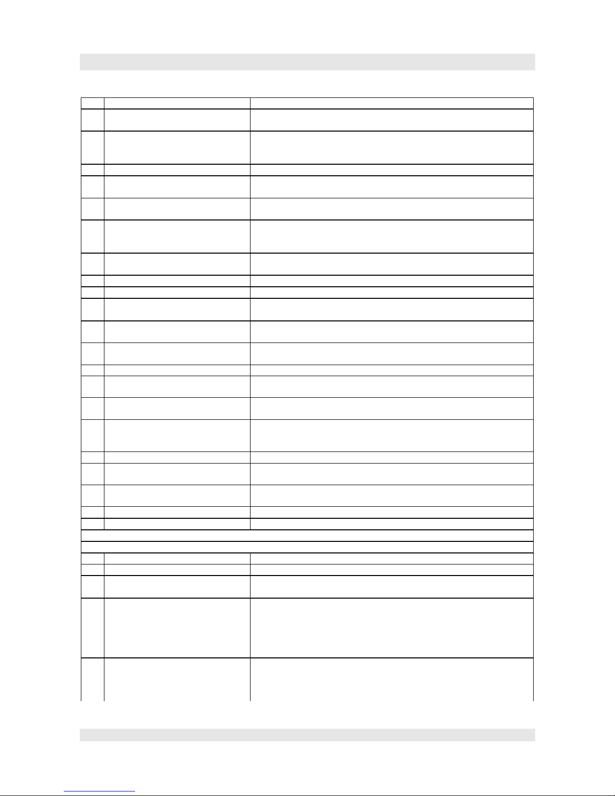
Standardfunktionen
1 Collectioncontrolling Collecting hall calls with respect on the given direction
2 Inspection Drive Manual drive up and down. Within the area of doors, the door open
button can be used for opening the door.
3 Self liberation with slow drive In case of missing the door area within the normal mode, the lift is
driving slowly with closed safets circuit into flush position and open the
door.
4 Test dive For Testcases, the lift can do a indicated number of accidentally test
drives.
5 Real time clock Errors are registred with date and time. Time-dependent funktions can
be activated.
6 Time to keep doors open Dependent of the kind of call(interior, exterior, service, special call), the
time to deep doors open can be indicated.
7 Door opening by lokal call Is the lift allready in the floor from which the call comes, the door
opens. With the Door open button, the door can be keept in open
position
8 Early door closing With the Close door button, the door can be closed, earlier than the keep
door open time frame.
9 Forced opening of doors Inside the door area, with the Door open botten, the door opening can be
forced for closed doors or doors which are actually close.
10 Controlling of door closing.
(return motion automatic)
In case the bar is not closed within 15 sec. after arrival at the door-closeendswitch, the door open again for a new try.
11 Controlling of door opening In case that 15 seconds after the door opened and the door-opend-
endswitch is not activated, the door is closing until further command.
12 Call cancel By doubble-pushing a call button, the call is canceled.
13 Terminal stops At paramount stage the up command gets canceled, at the lowermost
stage the down command gets canceled.
14 Direct drive Direct drive without rat run. This function is activated at standard when
incremental detection and analog trigger of the inverter.
The driving cycle is preset by the controller. There are no special
demands on the inverter.
15 Cabinet full If full load, the cabinet do not stop anymore for hall calls.
16 Cabinet light cut off After 5 minutes without any activity, the cabinet light will be switched
off.
17 Park drive After an indicated time without any activity, the lift drives to the main
purchase postion.
18 LCD controller Graphical display with comprehensive status informations and menu
navigation.
19 Analoge speed control The rotation speed of the frequency inverter is triggered by the analog
output
Page 4
Manual F5021B - System overview
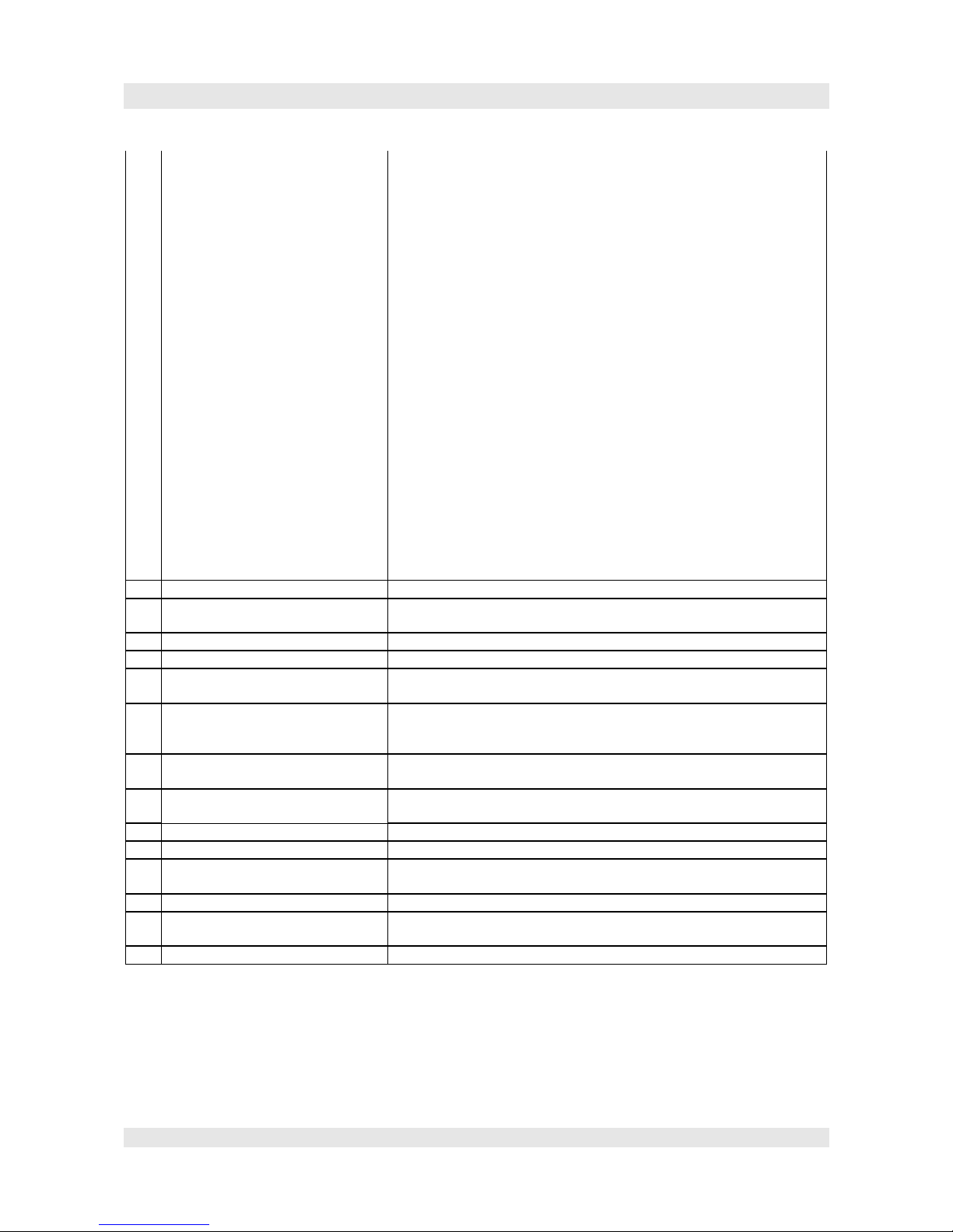
20 Digitale speed control Alternatively the speed can be controlled via contactors
21 Error memory The last 20 Errors get saved and displayed with information of time,
floor and error code.
22 Learn trip for schaft information The controller is learning with encoders and floor flags the bulk of the
schaft and stopping distance. After that, the lift can merge into standard
mode.
23 Floor approval Free adjustments of floors, which can be departed.
24 Adjustment of the floor display The icons, which should appear in the respective floors, can be free
adjusted to a large extent.
25 Liftboy control The lift gets drived via interior control manually. Hall calls will be
served.
26 Priority inside Hall calls are deactivated only interior calls are effective. The door must
be closed with the door-close-button. The Push-button have to be
compressed until the close-door-end-switch is activated.
27 LED-dot matrix-display,
LCD graphic-display
At every stop there ist a dot matrix display with floor update, direction
and status. The user can see that there is something going on.
28 Display with roll function Respectively to the drive direction, the display is „rolling“.
29 Automatic schaft data correction Continously the schaft datas gets corrected
30 Remote off The lift can be shut down, but before all still open cabinet commands
need to be completed.
31 Door only opens inside the door
areas
Outside the door areas, the cabinet doors can not be opened.
32 Safty light barrier/ light gate The safty light barrier/ light gate gets evaluated by the controller. In case
of activation, the controller avoids closing the door.
33 Overload In case of overload, the door stay open and an alert sounds (buzzer)
34 Abuse recognition If the cabinet is empty (empty load) the number of cabinet calls is
bordered.
35 Stop in case of wrong agitator
direction
In case the controller recognize a wrong agitator direction the handler
gets stopped.
36 Drive inspection (skidding) If the cabinet is not moving despite active handler, the handler gets
stopped after 40 seconds (drive inspection). New drives only possible
after Reset.
37 Inspection of traction In case of cabinet is moven despite deadlock, alarm get raised.
38 Inspections end switch The inspections end switch avoid, that the lift drives to the emergency
limit switch during inspections, return motion drives or learn trip.
39 Contactor monitoring The controller check at every drive the correct functionallity of the main
contactors and brake contactor .
40 Speed monitoring If over speed is detected an emergency stop will be effected
41 CPU monitoring The processor is monitored by watchdog, if needed restarted.
Optionale functions
1 preopening doors Using safty circuit
2 relevelling with open doors Using safty circuit. At hydraulic lifts standard function
3 Fire controll In case of fire signal the lift drive to the fire floor and stay there with
open door.
4 Fireman control All commands get canceled and the lift drives to the fire floor stage.
Now the firemen can use the lift. The door is not open atuomatically, but
have to be opened with the door-open-button. Unhand the button makes
the doors closing immediatelly.
European (EN81) und Russian (PUBEL) variant.
5 Additional COP It is easy to install a second car operation panel
6 COP for 2
nd
door Selective door control
7 Disabled COP Particular COP (e.g. desk COP) for disabled people (longer door
Page 5
Manual F5021B - System overview
opening times)
8 Duplex-function Via the second CAN-Bus 2 lifts can be conectetd to a two- groupe. The
lifts than parting calls respective to the actual situation; so it can be
achieved that the times of waiting can be reduced to a minimum. In
addition there can be activated a function, that, if there are no more open
calls, the one of the lifts which is nearer the main stop position, gets
driven there an keep it prepared there.
9 Group function With a optional group controler board, lift groups with up to 8 lifts can
be realized. The group control collects the hall calls and allocate these
respectivlly to the condition of the several lifts in order to reach short
time of waiting.
10 Rush hour handling – fill up
building
Via internal time frame inputs, the capacity can be adapted to the
building. (type office buildings)
11 Rush hour handling – clear building Via internal time frame inputs, the capacity can be adapted to the
building. (type office buildings)
12 Distribution of waiting lifts If there are no more open calls, the lifts of the groupe get distributed
after 1 min. in the buildding, means one drives to main stop position, the
others disperse themself, in order to achieve shorte waiting times.
13 Interface to building control service
engineering
RS485 interface for connection to a PC of the building control service
engineering.
14 Remote control The lift can be integrated into a region comprehensive remote control
system.
15 Lift arrival gong During the drive in, the gong on the cabin roof or under the cabin floor,
about the arrival of the lift.
16 direction indicator HOP Inside the exterior panels it is possible to instal an optical and akustical
continued travel display.
17 Floor gong For every stop an lift arrival gong can be arranged.
18 Card reader in the cabin With a transponder card, either a specific call can be activated or
defined calls can be approved.
19 Card reader at the floor Approval of exterior calls
20 Selective door triggering Frontside and backside of the lift can be controlled seperatly.
21 Scramble After one minute the door is closing slowling despite of the safty light
barrier.
22 VIP Service A key switch in exterior panels cancels all hall calls and fetches the
empty cabin. Now multiple interior calls can be done. After these calls
are done, the lift change back to standard handling.
23 PIN entry via Push buttons For certain floor approvals the Push buttons can be used for entering a
PIN.
24 Local controlled floor approval For several and duplex lifts a changed floor approval via key switch can
be activated.
25 Via group controlled floor approval Floor approvals can be temporary changed via the group add-on.
26 Temporary block of sereral floors Temporary, the user can block floors
27 Automatic evakuation In case of black out with following auxiliary power supply, the cabine
will be driven to the next stop.
28 Auxiliary power supply evakuation For lift groups an evakuation will be done separate one after another
29 Earthquake function Lift get stopped during the drive and will be driven to the evaktuaion
stop.
30 Voice message Serial and parallel access for voice message
Page 6
Manual F5021B - Operation equipment
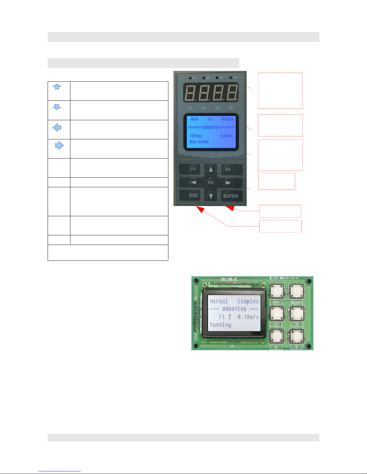
3. Operation equipment
Overview of push button functions:
Next parameter/ menu item
Increase the number of selected decimal
Former parameter/ menu item
Decrease the number of selected decimal
Jump 10 parameters back,
one decimal place to the left
Jump 10 parameters forward,
one decimal place to the right
ENTER Access parameter menu
parameter set/adopt
ESC Parameter/menu item leaving
F1
2x F1
3x F1
Hot key: change from status-window to
error display, to encoder diagnostic and
to CAN-diagnostic
F2
2x F2
Hot key: change to call entry and to
status display of in-/outputs.
F3 Hot key: to travel cycle display
All functions from F1 to F3 also accessable via the
menu!
Optional a control element can be directly inserted
on board F5021B, or the external control element
can be connected with a special cable with the 9pin
Sub-D-linkage JP15. The USB-plug of the cable
have to be pluged in the left plug (RS485). A plugin into the right plub by mistake arose no claims,
the control element is just not working.
Attention! Never use the special cable to link with
the PC. The PC can be damaged!
Again Attention!
The inserted control element and the external
control element may not be connected at the same
time! In case this occurs, there won´t be any damage, but the parameter are not possible to be setted
because two control elements at one time are not allowed to access the parameter memory!
Page 7
D1:driving
D2: up
D3: down
D4: error
Floor or
error code
LCD
with status
Menu, etc.
keypad
CAN
RS485
Manual F5021B - Operation equipment
Handling:
The handling via the inserted control element and the external
control element are identical. The external control element processes
additionally to the shortcuts F1, F2 and F3 whereby assinged
diagnostic-windows directly can be recalled. At the inserted control
element all windows only accessable via the menu.
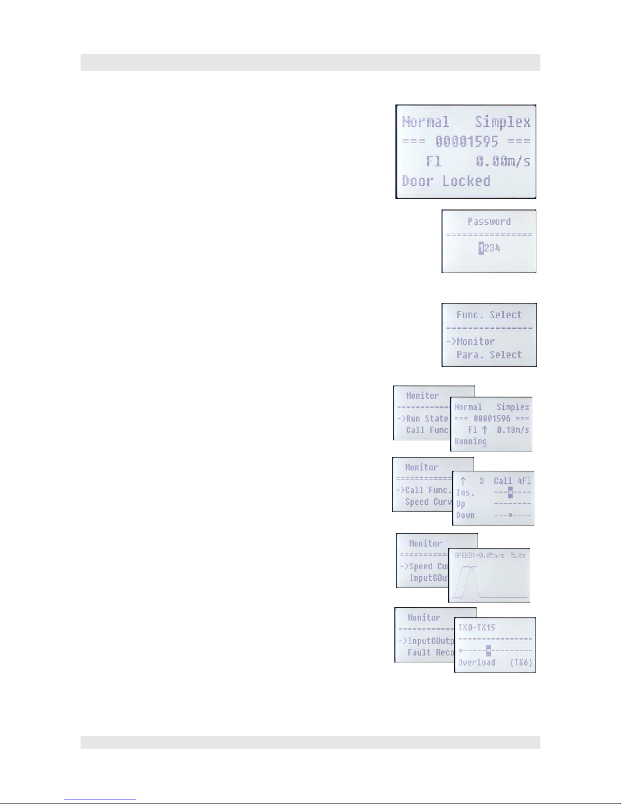
Log-in:
In order to see the status and for setting parameters, first you have to
log-in. In case you are not logged in yet, it is displayed after pushing
the ENTER button the window for log-in. By default the password is „1234“.
After log-in it is possible to change this in „Chg.Password“. Attention! Do not
forget the password!. The controller can without password only in the factory be
unlocked!
Menu
The complete menu tree you can find in: “Menu tree & parameter“.
The start window shows mode, group status, journey counter, floor, speed and the
actual activity. With Enter you can change to the main menu. Repushing Enter
show you the monitor-menu auf, which occupies all diagnostic windows.
Status window in Submenu „Monitor“
Run State is the start window.
In the first line you can see the mode (Normal, Inspection, Fire Return,
Firemen, Park) and the group status (Simplex, Group).
Among the journey counter, floor, speed and actual activity.
In Call. Func. are displayed the actuall calls and it is also possible to enter
calls (with the arrow buttons on the respective call and Enter).
Cabin call, hall calls for up and down.
Speed Curve is the graphical display of the as-is-value (of the encoder) of the
speed.
Above it is displayed the actual speed value and the time of journey.
At the window Input&Output it is possible to display all outputs and inputs.
With the up/down-buttons you can switch between the several 16fold groups.
With the right/left-buttons a single input/output can be marked. Than in the
line among is shown the function of the input/output.
The marking X (inputs SM01) and Y (outputs SM01), also TX (inputs SM02)
and TY (outputs SM02) you can find again in the diagram.
Page 8
Start window
Log-in
Main menu
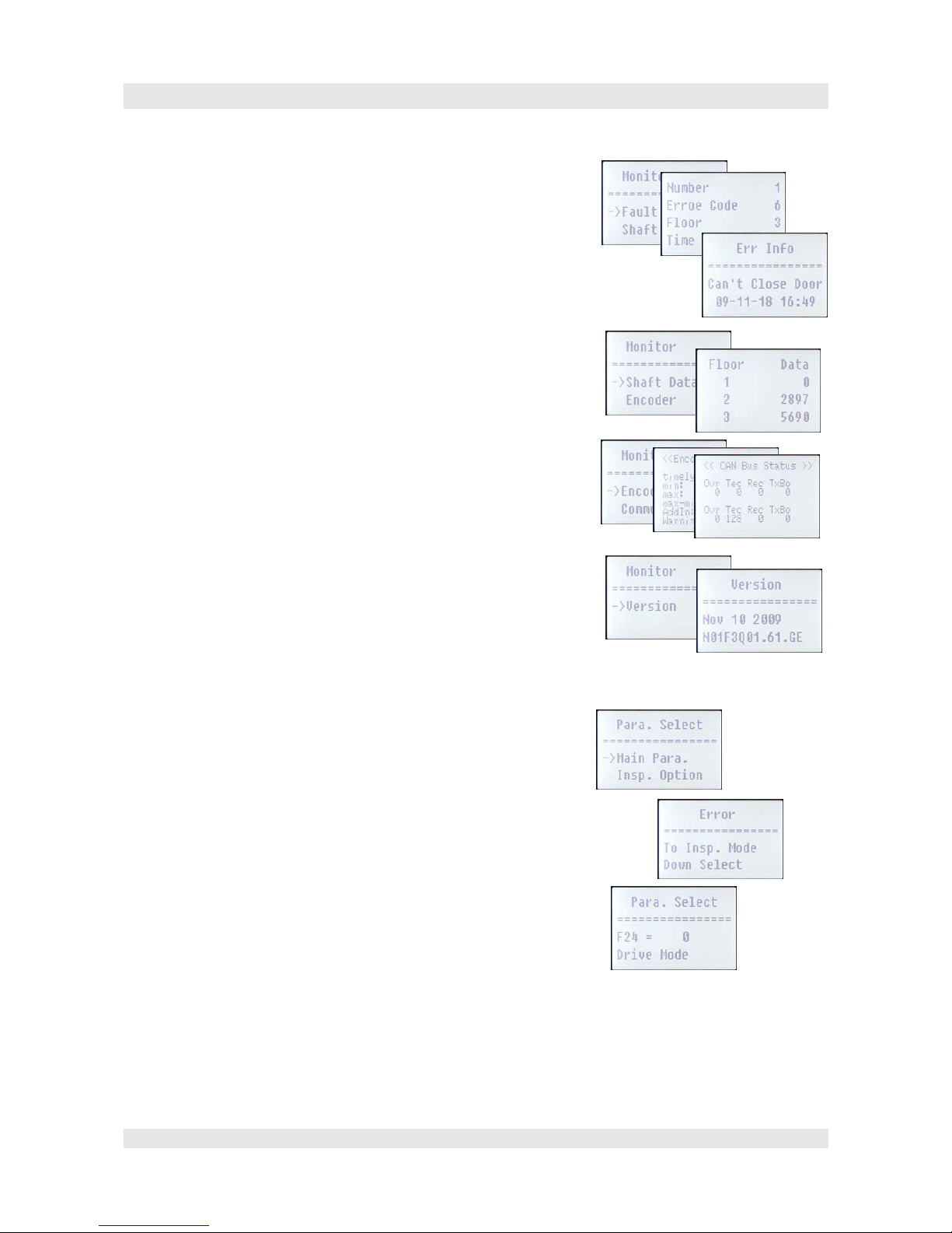
Manual F5021B - Operation equipment
In the error memory (Fault Record) there are displayed the last 20 errors with
date, time and floor.
The latest error is displayed at first.
With up/down you can move between the items in the list. With Enter an
additional window pops up, in which date, time and full-text-error message is
displayed.
The list Shaft Data contains the floor postions in mm which were identified at
the learn trip. If there are problems in the shaft selection you can really fast
identify if the floors were learned correctly.
The two windows Encoder Eva and Communication are helpful if you have
problems with the encoder or the CAN-bus.
In the version window are shown date and version number of the firmware.
Before doing an update it should be checked if the new software is really
more active than the allready existing version.
Parameter setting in the sub menu Para.Select
Via the parameter menu you can access to the numerous parameters. There are
parameter groups, in which the parameters combined thematically (e.g. engine
or door parameter), as well as a list in which all parameters are sorted by
numbers.
Most of the parameters can only be setted in the inspection or return motion
mode. If the alert window shows up, switch to inspection.
All parameter are achived as 16bit integer. Most of them are shown as
decimal, with adjustment value (e.g. means the value 50 at a device of 0,1s a
parameter value of 5 seconds).
Page 9
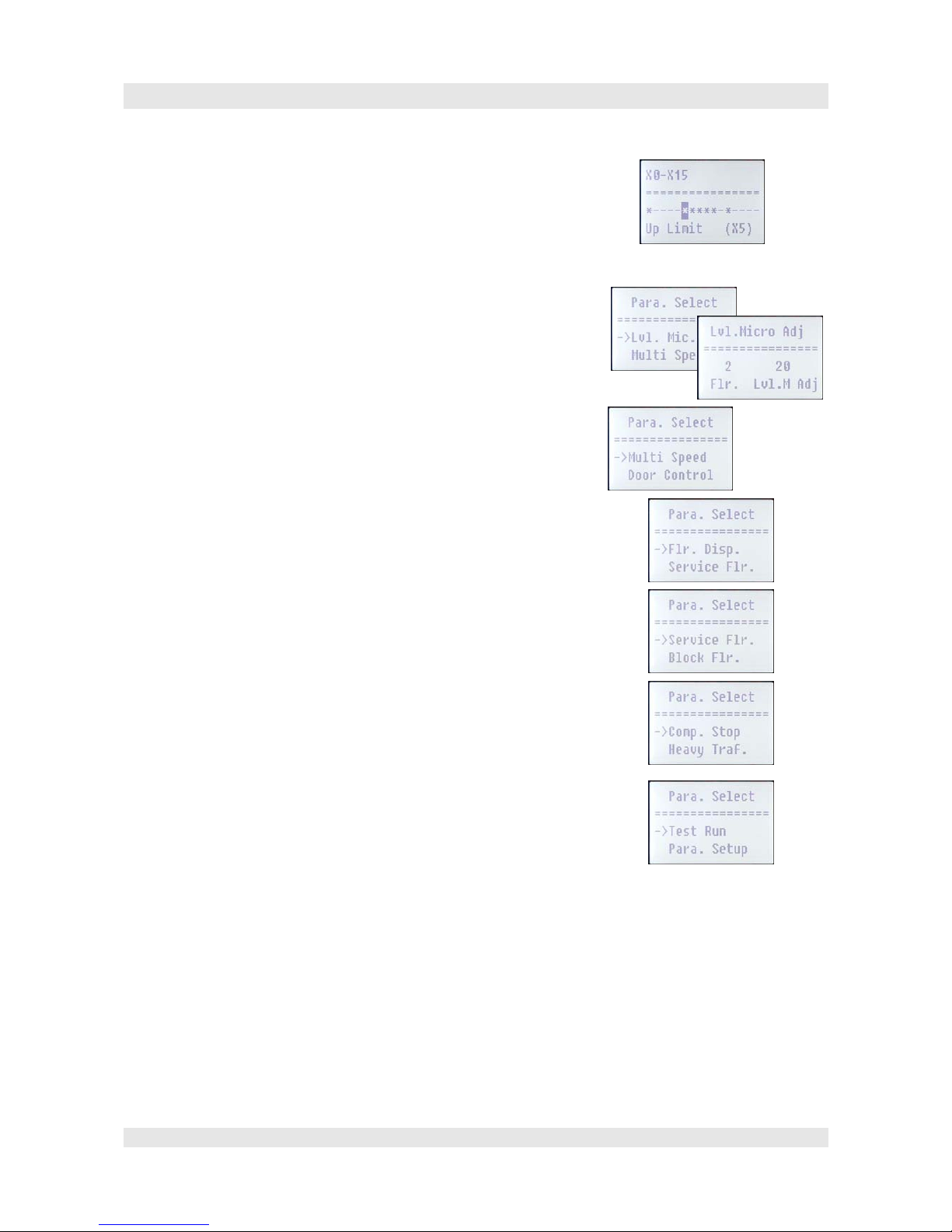
Manual F5021B - Operation equipment
Some parameters are available as bitmask. Indeed is shown the decimal, at
once you want to set the value, it will be shown as bitmask and you can set it
with right/left button (move between the bits) and up/down button (* means
setted/ - means canceled).
In the line below shows up the description of the bit.
Thus you can configure e.g. for every several input the logic (*NC/-NO)
Lvl.Mic.Adj. allows you the correction of serverl precisions in all floo rs.
Normally this is not necessary as the floors get messured at the learn trip.
Multi Speed contains all parameters, which are necessary for the handling of
the frequency inverters in multistep-mode (prallel control).
Door Control allows you to set parameter for the lift-door-control.
Flr.Disp. Guides you to the list with floor displays. For every floor it is
possible to do the settings for the displayed letter-combination. (at Step SM04
displays). At the same time, the display code configure the voice message,
which get annouced at the respective floor when lift drives in.
The display codes are configured in a table in the attachment.
Service Floor configure the floors, which are approved. Furthermore floors
can be configured, which are only can be unblocked via key-switch.
Block Floor allow the locking of a floor by time or key-switch.
Comp. Stop (forced stop) define stops, at which the lift by passing enforced
stops. In some cases it make sence for hotels.
Heavy Traf. Allows the configuration of the function fill-u p building and
clear building. By this, especially for office buildings, it is possible to
improve the hoisting capacity.
In Test Run it is possible to configure the parameter F34 to a number of
journeys, the lift have to do test journeay without any commands
(accidentially).
Para. Setup is the access to the complette parameter list.
Page 10
Manual F5021B - Operation equipment
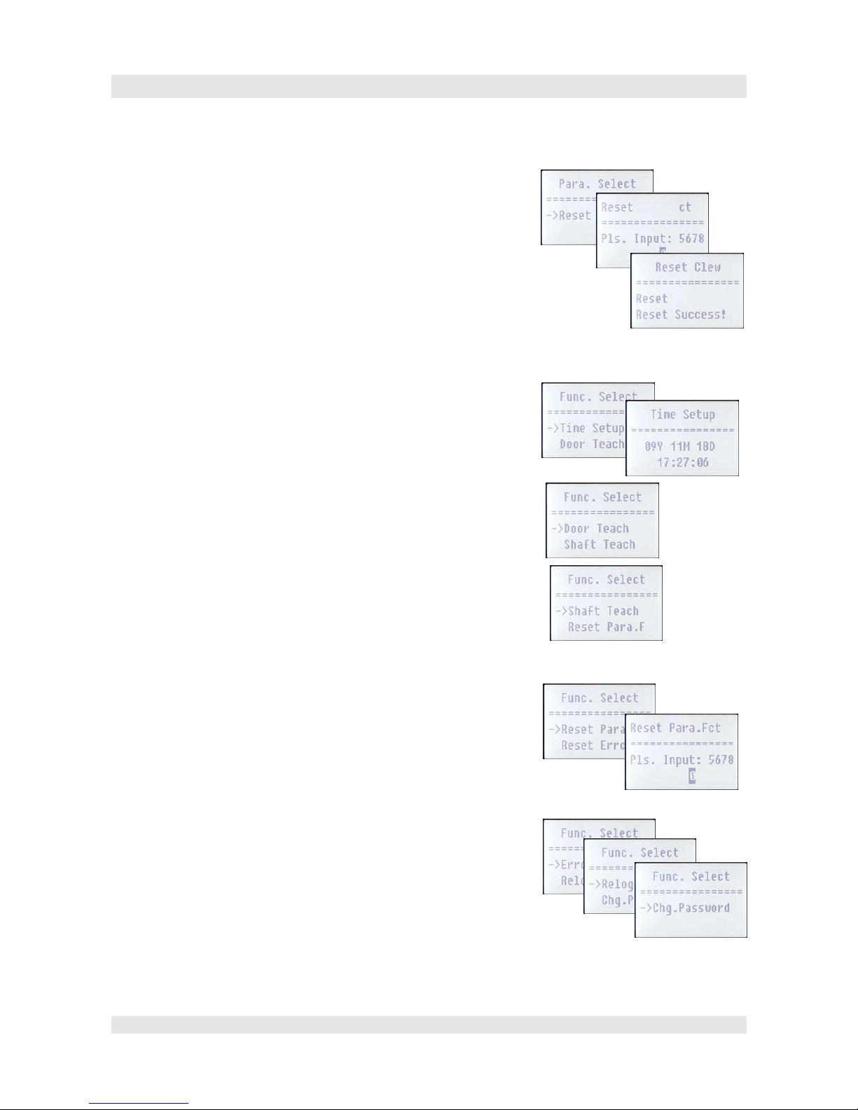
Reset restores all parameters to factory setting. This should only be done if
absolutly necessary. Before Reset there have to be entered a number in order
to avoid to do a reset by mistake.
Attention! After entry of the number the reset of all parameters starts without
any further query!
F146 necessarily have to be setted to “0“!
Different functions (Func.Select)
Time Setup: Configuration of the real time clock. This is used for Error
recording and the time relevant floor approvals and the function s fill-up
building and clear building.
Door Teach: Detect by opening and closing the function of the door-endswitches.
Shaft Teach:learn trip, have to be done before switch to standard mode (after
installation or change of door positions).
Door, bus, shaft selection and cabine light have to operate correctly.
After activation of the learn trip, the lift is driving self-consistent to the
lowermost stop and starts the learn trip. As soon as the learn trip is finished,
the lift can be switched to standard mode. If an Error occours, the learn trip is
stopped with an error message.
Reset Para.F: Restore to factory setting!!!
Reset Errco.: Clearance of the error memory!
Error Reset: Reset after Lift Error (fatal error) as e.g. drive monitoring,
contactor monitoring, brake monitoring, etc.
Relogin: Log out and if so new log in. Normally after 10 minutes without
operation the log out is automatically.
Chg.Password: Changing password. Attention! Do not forget password! Only
possible to can be restored without password in the factory!
Page 11


Manual F5021B - Menu tree & parameter
4.Menu tree & parameter
Func.SelectMonitor Run State Statu s of the lift (Floor, speed,. etc.)
Call Func Enter and display calls
Speed Curve Graphical display of the speed curve
Input&Output Status of the inputs and outputs
Fault Record Error memory
Shaft Data List of floor values
Encoder Analysis of encoder
Communicat. Analysis of CAN-system
Version Display of software version
Para.Select Main Para. Basic parameter
Insp.Option Inpection parameter
S-Curve Travel cycle parameter
Lvl.Mic.Adj Fine adjustment precision
Multi Speed Parameter for multistep operation
Door Control Door-parameter
Flr.Disp. Adjustment of floor display
Service Flr. Floor approval
Block Flr. Floor blocking (access control)
Comp.Stop Define forced stops
Heavy Traf. Fill-up build ing/ clear building
Test Run Number of accidential test drives
Para.Setup All parameters in one list
Reset Restore to factory setting!
Func.Select Time Setup Configure time
Door Teach Learns door-end-switches
Shaft Teach learn trip shaft
Reset Para.F Parameter to factory setting
Reset Errco. Reset Error memory
Error Reset Reset from error mode
Relogin Again log-in
Chg.Password Password change
Page 13
Manual F5021B - Menu tree & parameter
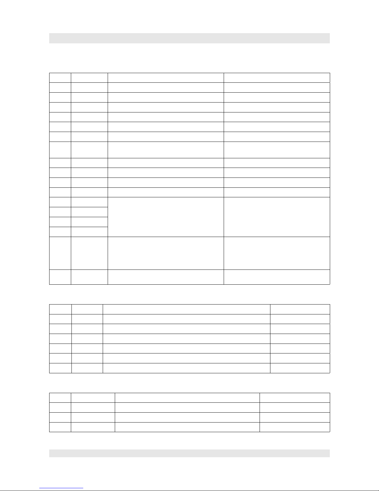
Basic-parameter (Main Para.)
No. Standard Description Advise
F6 1m/s Nominal speed lift
F7 1450rpm Nominal rotation speed engine
F8 1024ppr Encoder pulses
F24 1 Trigger of FU analog
F11 18 Number of floors
F182 1 Number of delay switches
F60 3 motor contactors : 3= K1 and K2 after the
inverter and monitored
F36 0 Break-monitoring-switch, 0= no monitoring
F153 0 Door lock det. type
F156 1 Safety loop type
F62 32 Journey time monitoring. For test set to 2s.
F25 35296 Configureing, if the several inputs wired as
closer (NO=normally open) or as opener
(NC=normally closed).
Depends on the diagram and the conected
switches
Bitmasks
F26 83
F27 835
F28 0
F23 0
Group function
0:Simplex, or rather Duplex-master
1:Duplex Slave
2:for external groupe processor
3:at group-ring (look at F181)
F181 0
Lift number within a group: minimum value have
most priority. (F32=3)
0~7; for F23=3
Inspections-parameter (Insp.Option)
No. Value Description Advise
F201 0 at 1 it is possible to drive above the reference-journey-end-switch For test purpose
F200 0 Distance for early stop at paramount stop (headgear) mostly UK
F40 Top Access Dis.
F42 Bot.Access Dis.
F64 1 0= no door operation for inspection
F165 Bit 1=0 Bit 1 avoid movements of door at inspection (door B)
Travel cycle parameter (S-Curve)
No. Value Description Advise
F0 0,55m/s² Acceleration
F1 0,55m/s² Deceleration
F2 1,3s Rounding at start
Page 14
Manual F5021B - Menu tree & parameter
No. Value Description Advise
F3 1,1s Rounding at the change to constant drive
F4 1,1s Rounding at leaving of constant drive
F5 1,3s Rounding at stopping
F12 0,25m/s Inspection speed VI
F13 0,06m/s Levelling speed VN
F48 Down Rev. Speed
F183 0,8m/s learn trip speed (for analog-trigger)
F21 6mm
V0 stop distance
F175 0,06m/s Creep speed at start
F186 0,5s Time of creep speed at start
F180 100,00% Analog value at nominal speed (Vmax)
F16 0,2 Time between inverter run signal and break release
F58 0,5 Deceleration of the driving cycle at start
F17 0,6 Deceleration of break after rotation speed Zero
F122 0,3s Time between break off and direction off
F141 0,5s Time between inverter run signal off and motor contactors
off
F144 0 Time between inverter direction off and inverter run signal
off
F56 50 Stopping distance up, >100 stop with creep speed
F57 50 Stopping distance down, >100 stop with creep speed
F126 300mm Short-journey deceleration distance
F193 0 Empty load-compensation Only relevant for very high
assets in order to balance
the weight of the ropes.
F194 0 Full load compensation lowmost stop
F195 0 Full load compensation paramount stop
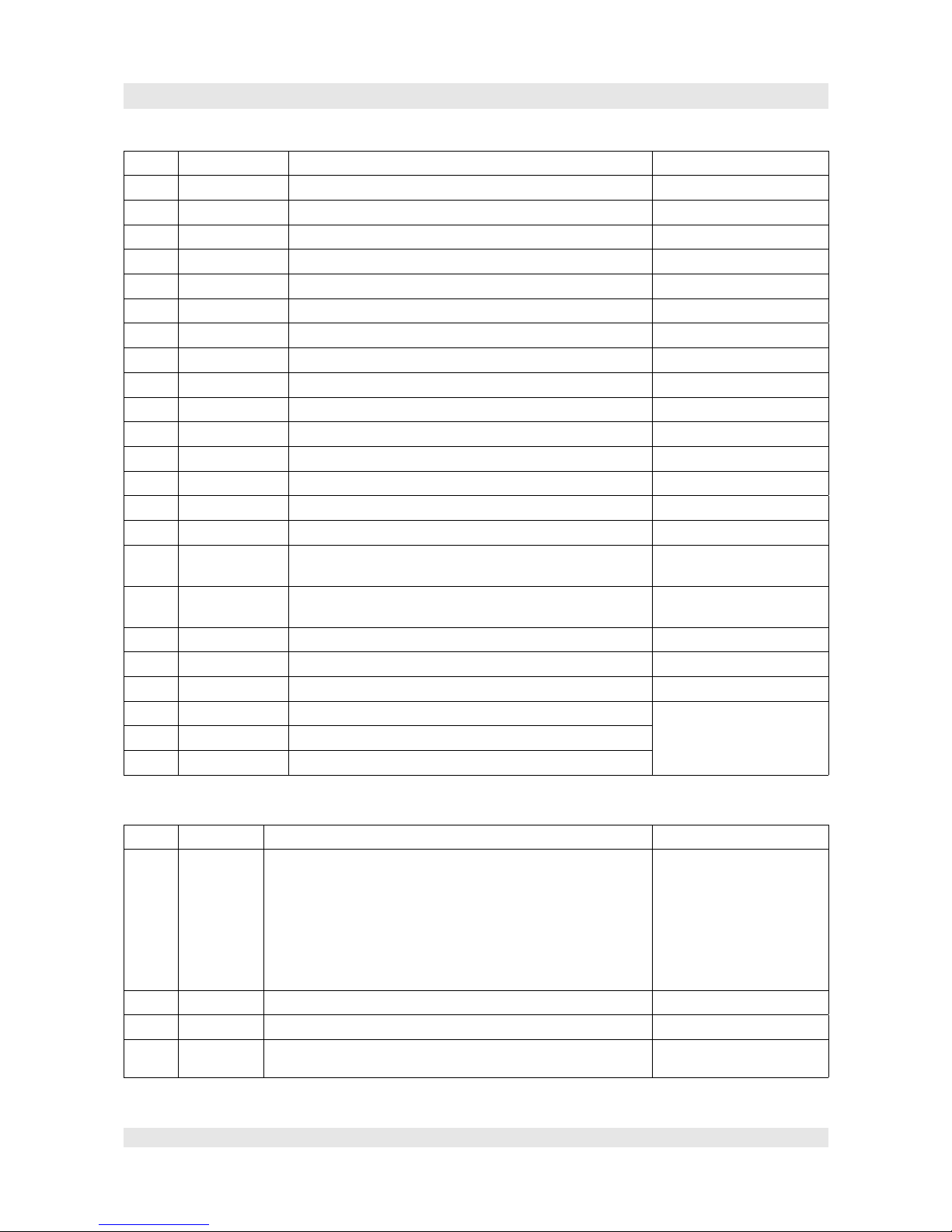
Multistep-parameter (Multi Speed)
No. Value Description Advise
F32 0
Type of frequency inverter:
0: YASKAWA,CT,FUJI,iAStar
1:SIEMENS
2: KEB
3: MICO
4: SIEI
5: Dietz
6: NEW FUJI
7: user-defined (look at F240~F249)
F63 2
Number of drive positions at Multistep-controler of inverter
F16 0,2s
Deceleration between inverter run signal and break contactor on.
F17 0,6s
Deceleration between inverter stop command and break
contactor off
Page 15
Manual F5021B - Menu tree & parameter
No. Value Description Advise
F58 0,5s
Deceleration between FU run signal and start of drive cycle
F122 0,3s
Time between break off and FU drive signal off (speed and
direction) .
F141 0,5s
Follow-up time of the engine-schuetze: approval off=>Schuetze
off.
F144 0,000s
Follow-up FU-approval after switch off the direction signal.
F21 6mm
V0 stop distance
F45 1,300m
Breaking distance for V1 (floor drive)
F46 2,900m
Breaking distance for V2 (2 floors drive)
F47 4,000m
Breaking distance for V3 (more floors drive)
F157 5,500m
Breaking distance for V4 at 4 floors drive (for fast lifts)
F158 6,500m
Breaking distance for V5 at 5 floors drive (fast lifts)
F126 300
Short drive deceleration distance
F143 0
spare
F147 0
spare
F56 0
Fine adjustment for stopping upwards: 50 for direct drive in,
>100 with creep speed
F57 0
Fine adjustment for stopping downwards: 50 for direct drive in,
>100 with creep speed
F240 0 Release brake
User defined Multistep
control of the frequency
inverter:
F24 = 0,F32 = 7
F241 4 Inspection slow
F242 4 Releveling
F243 3 Creep speed
F244 4 Inspection fast
F245 5 Speed floor-drive-in
F246 6 Speed 2-floor-drive-in
F247 7 Speed 3-floor-drive-in
F248 1 Speed 4-floor-drive-in
F249 2 Speed 5-floor-drive-in
door Parameter (Door Control)
No. Value Description Advise
F50 65535 Door A approval floor 1 to 16
F51 65535 Door A approval floor 17 to 32
F52 65535 Door A approval floor 33 to 48
F191 65535 Door A approval floor 49 to 64
F53 0 Door B approval floor 1 to 16
F54 0 Door B approval floor 17 to 32
Page 16

Manual F5021B - Menu tree & parameter
F55 0 Door B approval floor 33 to 48
F192 0 Door B approval floor 49 to 64
F128 0 0= charging, 1 = selective door control
F130 0
Door control (keep closed/keep open):
0:no keeping of closed/open
Bit 1:keep door open (in case cabin door get drawed back
from shaft door)
Bit 2:keep door closed (in case door-bracing opens without
keep-shut moment)
Bit 3:keep shut during travel (in case door-braking would
bump against the bar)
Bit 4:no door-close-end-switch
Bit 5:AT120 door control
Bit 6:manual door
F140 0
At door open, second doorzone active:
0:X9/X10 configures door opening.
1:X18 configures door opening
F129 0
re-levelling with open door/ in advance door opening (require
safety circuit):
0:no safety circuit
1:preopening door
2:re-levelling with open door
3:both
F14
Door-open-time frame after hallr call
F15
Door-open-time frame after car call
F121 0
Door scramble:
0:on, 1:off
F115 15
Run-time at door closing (in case there is no end-switch)
F116 15
Run-time at door opening (in case there is no end-switch)
F117 60s
Door open time frame after confirmation keep-door-openbutton.
F118 30s
Door open time frame after confirmation open-door for
disabled person.
F165 0
Door opening functionallity:
Bit 1: no opening/ closing during inspection.
Bit 2: no opening of doors during test mode
Bit 3: Door A basic postion open at main stop
Bit 4: Door A basic postion open at every stop
Bit 5: Door B basic postion open at main stop
Bit 6: Door B basic postion open at every stop
F142 0,1s
Follow-up time of the door-engine-contactors (after end-switch
confirmation)
F145 2 spare
F119 0
Door mode when priority inside
0:keep close-door-button pushed for closing the door
1:Door is closing after command
Floor display adjustment (Flr.Disp.)
No. Value Description Advise
F65 49 Display Code for floor 1
Page 17

Manual F5021B - Menu tree & parameter
F66 1 Display Code for floor 2
F67 etc. Display-codes in respect to the table in the attachment.
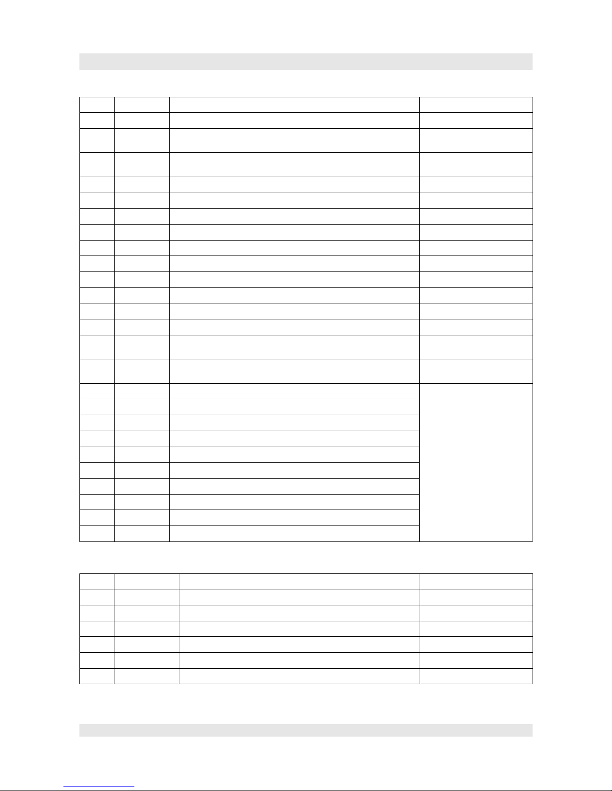
Floor approval (Service Flr.)
No. Value Description Advise
F29
65535 Approval floors 1 - 16
Enter as bitmask!
F30
65535 Approval floors 17 - 32
F31
65535 Approval floors 33 - 48
F190
65535 Approval floors 49-64
F137
65535 Defines floors, which can be blocked with key-switch:
Bitmask 1-16
F138
65535 Bitmask 17-32
F139
65535 Bitmask 33-48
F199
65535 Bitmask 49-64
F236
65535
NS-CB Floor 1-16
F237
65535
NS-CB Floor 17-32
F238
65535
NS-CB Floor 33-48
F239
65535
NS-CB Floor 49-64
Floor blocking (Floor Block)
No. Value Description Advise
F161
0 Floor blocking (F137,F138,F139)
0: no block
1: block by time F131
2: block by key-switch
F131
0 Floors able to block
0: inactive
1~64: number of the floor to block.
F132
0 Time from when floor <F131> have to be blocked: e.g. 730 for
7:30.
F133
0 Time from when floor <F131> have to be un-locked. e.g.: 930 for
9:30.
Forced stop definition (Comp. Stp.)
No. Value Description Advice
F134
65535 Bitmask floors 1 - 16
When crossing the setted floors, the lift mandatory
stops, even without command.
Makes only sence in hotels.
F135
65535 Bitmask floors 17 - 32
F136
65535 Bitmask floors 33 - 48
Fill-up building/clear building definition (Heavy Traf.)
No. Value Description Advice
Page 18

Manual F5021B - Menu tree & parameter
F231 0
Approval for function fill-up building/ clear building
0: no function
1: fill-up building
2: clear building
3: both functions
F232 730
Starting time for fill-up building: e.g. 730 means 7:30
F233 930
Finish time for fill-up building: e.g. 930 means 9:30
F234 1700
Starting time for clear building: z.B. 1700 means 17:00
F235 1830
Finish time for clear building: z.B. 1830 means 18:30
Page 19

Manual F5021B - Menu tree & parameter
Page 20

Manual F5021B - Shaft selection
5.Shaft selection
The shaft selection consists of a incremental encoder and
solenoid switches, respectiveley sensors.
The incremental encoder optinally is positioned on the
engine or in the shaft.
Especially for rope lifts it is used the encoder of the
engine, which can hand over at the most of the frequency
inverters via encoder output (encoder simulation) to the
controller.
In this case it is entered the effectiv datas for the
parameters F6 (nominal speed), F7 (engine speed) and F8
(encoder release).
For slowly running synchronous motors it mostly have to
be juggeled with the parameters nominal-rotation-speed
and encounter-puls-rate. E.g. 150U/min at 2048ppr
changed to 600U/min (*4) and 512 ppr.
If the encoder is assembled in the shaft (rotating string) for
the nominal-rotation-speed have to be entered an
equivalence-rotation-speed (equates encoder-rotationspeed).
For the system used by us with carbon cord show up the
following values:
(F7) 0,8 1 1,2 1,4 1,6 m/s
(F8) 294 367 441 514 588 RPM
re-levelling sensors:
As the shaft selection is done with the engine encoder, the slip of the tractions sheave have to be
compensated. For this, there are in every floor re-levelling-plates installed with about 220mm length. (The
Page 21
Car
Car
C
D
C
D
KO1
KO
IEO
NEO (Emergency stop T O P )
(Inspection stop TOP)
(Downs lo w switch TOP)
Downslow switch v>2.5m/s
KO1
only if v>2.5m/s
KO
IEO
NEO
KU1
v>2.5m/s
KU
IEU
NEU
KU1
KU
Inspection switch
DOWN
EmergencyStop
DOWN
Downslow switch v>2,5m/s
Downslow switch
DOWN
IEU
L.KO
L.KO1
L.IEO
L.NEO
L.KU
L.KU1
L.IEU
L.NEU
0,63m/s:
1,0m/s:
1,6m/s:
1,8m/s:
2,0m/s:
2,5m/s:
950
1300
2400
2600
2400
2400
v
Distance (mm)
L.KO
3800
5600
L.KO1

Manual F5021B - Shaft selection
length is not important, but it have to be identic in all floors).
This plate will be evaluated by two inductiv sensors C and D. C is the upper, D the
lower.
Solenoid switch:
Additionally there are in the shaft ceiling and in the shaft pit each 2 bi-stable solenoidswitches (there could also be roller-switches with repective curves at the cabin). Correction
above and below, as well as inspection-end above and below.
It is important, that the switches are installed as opener. By crossing the above correction- and inspectionswitch they have to be open on the upper side and closed on the lower side. For the lower positioned ones,
the same is valid respectively contrairiwise.
Correction switch
The correction switches serve the deceleration at the termian end stops in case of error (blackout of
incremental encoder) and for learn trip. They are also used for correction of the incremental-encoder-datas.
In the set of drawings, page 50 you can find these respectivly to the speed recommendet distances. The
exact pitch for the braking distance which is choosen by the controller is not important, as this is assigned
by the chossen parameters. However, braking distance and pitch should not have a bigger difference than
45cm.
Inspection end switch
The lower inspection end switch have to be installed in that way, that it opens right before the emergency
limit switch is activated, but after the re-levelling-sensor D lower the precision plate is freed. C is
mentionend in the plate.
For the upper inspection switch it is in the respective way, means IEO will be activated (open contact) if
the sensor C is upper the precision plate and D is still at the plate. Also in this case the emergency limit
switch should be a bit away, that the lift stops before the emergeny limit switch is activated.
The inspection end switches are important for the learn trip.
Page 22
1
2
0
5
0
220
200

Manual F5021B - Shaft selection
Intelligent magnetic sensors iMS45
Meanwhile, all above mentioned switches are integrated in one compact
sensor-system. Due to this the montage and adjustments are made really easy.
The iMS45 have up to 4 solenoid sensors, which are together with a
programm able analysis-electric can generate up to eight switching signals. For a complete shaft selection
one iMS45-POS is enough. Especially for machineroomless an additonal iMS45-SPD sensor will be
attached, which detect the speed and rotation of the driving wheel. This is displayed at the Drive monitor,
which is the display and analysis unit.
The sending of datas itself will be done via a serial conection without malfunction rate RS485-connection.
Assembly and function
Assembly
The sensor is in a stable aluminium housing, which is also available as IP54-version which is used in
firefighter lifts.
The solenoids are flat solenoids with 15mmx7mm of cross-section and a variable length. The solenoids are
installed at the button of the arrester rails.
Function
In the iMS45 are 4 solenoid sensors, which are measuring the strengh and polarity of the magnetic field.
An analysis unit detect the respective switching signals and send these serial to the cabine, respectively to
the drive (driving wheel) for controlling/ stearing. Additionally the iMS45-POS have an independent
transistor output for e.g. contacting a chanel of a security circuit.
different detections:
* Single magnet north
* Single magnet south
* Doubble magnet upper north/ lower south
* Doubble magnet upper south/ lower north
* Tripple magnet north in the middle
* Tripple magnet south in the middle
* Crossing direction
* Crossing speed
* North/south transition is detected exactly of each milimeter, mostlikely independent on the distace
sensor/ magnet
Page 23

Manual F5021B - Shaft selection
Montage scheme iMS45_POS
Montage scheme iMS45_SPD (only for machine room less lifts)
Page 24
50
0
Ver.
M.Aicher 09.11.2009
A
B
C
D
E
54321 6 7 8
brown
black
white
blue
+10...30VDC
Out E NPN 200mA
sLink
0V
6
+5
-5
S
N
S
N
N
S
N
S
N
Track Pos (Levelling X9/10, Doorzone
Slowdown X7/8 and X3/X4
Learntriplimit X5/6)
Top Floor
Floor 2....
Bottom Floor
Slowdown magnet down (only bottom floor)
doublemagnet round
with north magnet above south magnet
Slowdown magnet up
doublemagnet round
with north magnet below south magnet
Levelling and Doorzone:
flat magnet
Width 10, Depth 8, Length 150mm
Northmagnet (blank)
flat magnet
Width 10, Depth 8, Length 150mm
southmagnet (marked with white)
reference point
slowdown X8
name date
created
last modif.
magnetic sensor, shaft selector
No:
Page
floor 2 ...n-1: no slo wmagnets required!
3
1
4
2
Sensor
10..30V
0V
E
RS485
5
gray
D+
D-
3
1
2
4
5
1
3
2
4
5
Ub
GND
D+
DE
brown
blue
white
black
gray
LED1
LED2
POS
S
N
S
N
S
N
S
N
S
N
N
S
Top Floor
Triple magnet (North in the middle)
defines Learntripli mit up (X5, IEO)
double magnet short
north below
Reference point
slowdown up (X7)
slowdown X8
double magnet north above south
triple magnet (south in middle)
defines learntrip limit x6
double magnet north above south
long magnet north
reference point floor level
short magnet south
short magnet north
Polarity North or South means the pole which
shows to the sensor.
South is marked with
white
.
Reference point floor level
shortmagnets length 20mm
longmagnets length 150mm
short magnet south
short magnet north
long magnet south
reference point floor level
Attention!
Sensor POS is asymetrical! The active Sensor element
must show to the guiding rail (marked).
Pos sensor must be always right from rail.
Wrong installation may cause malefunction.
LED1: Sensor is online (connection t o DriveMonitor Ok)
LED2: Sensor is detecting magnet
position sensor
distance by speed = 1.0 m/s
1,4m
distance by speed = 1.6 m/s
2,8m
distance by speed = 1.0 m/s
1,4m
distance by speed = 1.6 m/s
2,8m
52
0
Ver.
M.Aicher 09.11.2009
A
B
C
D
E
54321 6 7 8
brown
green
yellow
white
+10...30V DC
sLink
0V
6
+5
-5
name date
created
last modif.
magnetic sensor, Speed Sensor
No:
Page
3
1
4
2
Sensor
10..30V
0V
E
RS485
5
D+
D-
3
1
2
4
132
4
Ub
GNDD+D-
LED1
LED2
SPD
LED1: Sensor is online (connection to DriveMonitor Ok)
LED2: Sensor is detec ting magnet
speed sensor
Speed-Sensor MS485 SPD at traction wheel
Position of sensor important for speed
and direction detection!
In case of wrong direction on DriveMonitor
turn sensor 180°.
polarity and
number of
magnets not
important.
5 or 6 magnets
around the wheel
are ok
check that sensor is in right position,
because for correct function
the sensors must be mounted
in the right way!
312
4
5
traction wheel
magnets round D=6mm
Manual F5021B - SM01 F5021 main board
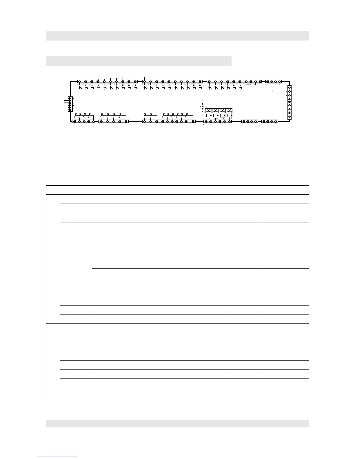
6.SM01 F5021 main board
SM01 F5021 Mainboard Terminals
Configuration of inputs and outputs:
The in- and outputs are limited free configurable. The following table shows the basic settings which are
ok in the most of cases. Some signals have a different configuration in some special cases. These specials
you can find in the electrical drawing of each case. Thus significant is the electrical drawing.
SM01 terminals:
Terminal Name Description Function Advise
JP1 1 X0 Signal inspection on, respectively normal operation input N
2 X1 Inspection/return motion up input N
3 X2 Inspection/return motion down input N
4 X3 Delay switch upwards/above for v>2,5m/s,
at short stop in the upmost stop.
input N F24=5
Counting impulse B (hydraulic lift with magnet switch) F24=3
5 X4 Delay switch downwards for v>2,5m/s,
at short floor in the lowest stop.
input N F24=5
Counting impulse A (hydraulic lift with magnet switc) F24=3
6 X5 learn trip -end-switch upwards/top input N
7 X6 learn trip -end-switch downwards/down input N
8 X7 Delay switch upwards/top input N
9 X8 Delay switch downwards/down input N
10 X9 re-levelling upwards (levelled) input N
1 X10 re-levelling upwards (levelled) input N
2 X11 Converter error signal or ready signal input N Rope lift
Monitoring approval-relay of the downwards valve Hydraulic lift
3 X12 Firedepartement-controlling on input N
4 X13 Fire stop 1 input N
5 X14 Fire stop 2 input N
6 X15 Motor contactor K1 Monitoring input N
7 X16 Motor contactor K2 Monitoring input N
Page 25
1 2 3 4 5 6 7 8 9 10
JP1
X0 X1 X2 X3 X4 X5 X6 X7 X8 X9
1 2 3 4 5 6 7 8 9 10
1 2 3 4 5 6 7 8 9 10
JP2
X10 X11 X12 X13 X14 X15 X16 X17 X18 X19
2011 12 13 14 15 16 17 18 19
1 2 3 4 5 6 7 8 9 10
JP3
X20 X21 X22 X23 X24 X25
21 22 23 24 25 26
1 2 3 4 1 2 3 4 5
JP9
Y0 Y1 Y2 Y3 Y4 Y5 Y6 Y7
D1 D2 D3 D4 D5 D6 D7 D8
1 2 3 4 5 6 7 8 9 10
JP11
Y8 Y9 Y10 Y11 Y12 Y13 Y1 4 Y15
D9 D10
D11 D12 D13 D14 D15 D16
1 2 3 4 5 6
JP12
JP6
1234
Speed 0-10V
0V(AGND)
1 2 3 4
1234
JP4
JP5
TXA+
TXA-
TXV-
TXV+
TXA+
TXA-
TXV-
TXV+
JP20
1
2
3
4
5
6
0V
0V
+5V
+24V
0V
0V
200
100
2 3 4
JP8
V+:15V
V-: 0VA>B>
1
normal/inspect ion
manual up
limit switch up (learn trip)
limit switch down (l e arn trip)
slow down switch up
slow down switch down
up levelling
down levelling
fire return home
error inverter
contactor monitoring
motor contactor 1
analog output
encoder input
speed governor
inputs 230VAC
see LED X26,X27,X28,29
5
FireStop1
FireStop2
automatic
evacuation
manual down
up limit switch (v> 2 m/s)
down limit switch (v >2m/s)
Autotuning is ac tive
contactor monitoring
brake contactor
monitoring safety c ircuit
inverter RUN
motor temperature
shutdown
brake closed
brake monitori ng
brake opened
brake abrasion
monitoring
CAN1
(car, shaft)
CAN 2
(group)
X26
X27
X28
X29
JP10
2 3 4
JP7
B-B+A-
A+
1
encoder input
sym.
X26 X27 X28 X29

Manual F5021B - SM01 F5021 main board
Terminal Name Description Function Advise
8 X17 Break contactor K8 Monitoring input N Rope lift
Monitoring of the valve approval relay Hydraulic lift
9 X18 Door-zone-signal/ monitoring of safety circuit input N
10 X19 Inverter RUN signal (open breaks signal) input N Rope lift
Softstart RUN signal (Approval for drive upwards) Hydraulic lift
JP3 1 X20 Monitoring of the engine temperature input N
2 X21 Lift shutdown at the next stop input N
3 X22 Monitoring open breaks input N Rope lift
Monitoring minimum preasure Hydraulic lift
4 X23 Monitoring closed breaks input N Rope lift
Monitoring preasure relief Hydraulic lift
5 X24 Anti surf (shaft door monitoring) deactivation input N
6 X25 automatical evacuation on input N
7 COM common mass for inputs
8COM
9 COM Feed-in mass of the optocoupler 0V feed-in
10 +24V Supply of the optocoupler 24V feed-in
JP4 1 TXA1+ CAN_H of CAN-Bus 1 inside the lift datas Use Twisted Pair
lines!
2 TXA1- CAN_L of CAN-Bus 1 inside the lift datas
3 0V GND
4 +24V +24V
JP5 1 TXA2+ CAN_H of CAN-Bus 2 for lift groups datas Use Twisted Pair
lines!
2 TXA2- CAN_L of CAN-Bus 2 for lift groups datas
3 0V GND
4 +24V +24V
JP6 1 AI1 Analog output current 4...20mA output AI
2 AGND Feed-in mass for analog output supply
3 AVS Analog output power 0...10V speed set point FU output AV
4 AVL Analog output power 0...10V torque set point FU output AV
JP7 1 B- Encoder input channel B symmetric input RS422-
2 B+ input
RS422+
3 A- Encoder input channel A symmetrisch input RS4224 A+ input
RS422+
JP8 1 +15V Powersupply for HTL encoder!! supply output Attention! Do not
conect 5V encoder!
Page 26

Manual F5021B - SM01 F5021 main board
Terminal Name Description Function Advise
20V
3 A HTL inputs A and B (Open Collector) 0-100kHZ
4B
JP9 1 Y0 Pre-controller-relay break contactor K8 relay-output Rope lift
Valve-approval-relay Hydraulic lift
2 Y1 Pre-controller-relay break contactor High voltage for
arround 2s
relay-output Rope lift
Approval-relay downwards-valve Hydraulic lift
3 Y2 motor contactor K1 relay-output
4 Y3 motor contactor K2 relay-output
5 COM1 COM of relay-contacts Y0-Y3
JP10 1 Y4 Door-open relay door A relay-output
2 Y5 Door-close relay door A relay-output
3 Y6 Door-open relay door B relay-output
Collected malfunction message Circuit plan!!
4 Y7 door-close relay door B relay-output
Engine tuning FUJI Gearless with incremental encoder Circuit plan!!
5 COM2 COM of relay-contacts Y4-Y7
JP11 1 Y8 Trigger K14 (bypass door switch) relay-output For Safety circuit
2 Y9 End of automatical evacuation relay-output
3 COM3 COM of relay-contacts Y8-Y9
4 Y10 Trigger frequency inverter upwards relay-output Rope lift
valve fast open Hydraulic lift
5 Y11 Trigger frequency inverter downwards relay-output Rope lift
valve slow open Hydraulic lift
6 Y12 Inverter Run-signal relay-output Rope lift
valve fast down Hydraulic lift
7 Y13 Multi-Step 1 speed signal relay-output Rope lift
valve slow down Hydraulic lift
8 Y14 Multi-Step 2 speed signal relay-output Rope lift
LRV inspection Hydraulic lift
9 Y15 Multi-Step 3 speed signal relay-output Rope lift
LRV additional speed Hydraulic lift
10 COM4 COM of relay-contacts Y10-Y15
JP12 1 N N-wire of the input terminals inputs
230VAC for
scan of the
2 X26 Scan emergency stop sector of the safety loop
3 X27 scan end of safety loop
Page 27

Manual F5021B - SM01 F5021 main board
Terminal Name Description Function Advise
security
circuit
4 X28 scan revolving door contacts
5 X29 additional highvoltage input
6 N N-type to the engine and break contactor
JP20 1 GND Voltage supply contact of the main board
2 GND
34 +24V
5 GND
6 GND
JP15 1 DCD RS232 interface
2 RXD RS232 interface
3 TXD RS232 interface
4 DTR RS232 interface
5 SGND RS232 interface
6X
7X
8X
9 +5V Only active if jumper J2 is installed. (hand terminal)
JP22 1 X
2 GND
3 D+ RS485-A
4 D- RS485-B
Page 28

Manual F5021B - SM02/SM03 cabin module
7.SM02/SM03 cabin module
Advise:
This SM02 will be replaced in future by SM02/H (in the cartop box) and SM03/G (in the COP). The
trigger of the doors (open and close) won´t be done anymore by SM01 in the control cabinet; this will be
done by SM02/H in the cartop box. (changed configuration)
SM02 Anschlüsse
Terminal Name Descripion Function Advise
JP2 1 TY0 direction upwards relay-output
2C.TY0COM TY0
3 TY1 direction downwards relay-output
4 C.TY1 COMTY1
5 TY2 Cabin light switch off relay-output
6 C.TY2 COMTY2
Page 29
432
1
4
3
2
1
4
3
2
1
1
2
3
4
5
6
7
8
9
10
11
12
13
14
15
16
17
18
19
20
4
5
1
2
3
6
7
8
9
10
11
12
13
14
15
16
17
18
19
20
COM (0V) TX0 -TX18
TXV+
TXV-
TXA+
TXA-
com+
com+
TY0
TY1
TY2
TY3
jp3
jp2
j1
JP1
RS485
JP7
TY4
TY5
+24V
+0V
CAN
JP9
JP10
4
3
2
1
4
3
2
1
4
3
2
1
4
3
2
1
4
3
2
1
4
3
2
1
4
3
2
1
4
3
2
1
JP1
JP2
JP3
JP4
JP5
JP6
JP7
JP8
SM-02
SM-03
JP1
JP2
JP3
JP4
JP5
JP6
JP7
JP8
1
2
3
4
5
6
7
8
9
10
11
12
13
14
15
16
17
18
19
20
21
22
23
24
25
26
27
28
29
30
31
32
1. 2. 3. 4. SM-03
com+
com+
to Voice Announcer
TX18: not used
TX17: fireman keyswitch
TX16: car light monitoring
TX15: Button Inspection fast
TX14: keep door open (handicaped)
TX13: light gate B
TX12: door close limit B
TX11: door open limit B
TX10: insp. door open
TX9: priority
TX8: insp. door close
TX7: empty load
TX6: safety edge door B
TX5: safety edge door A
TX4: full load
TX3: overload
TX2: light gate A
TX1 door close limit A
TX0: door open limit A
door close btn TX20
door close indic.
door open btn
door open indic.
arrow UP
arrow down
car light off
gong
overload indicator
buzzer

Manual F5021B - SM02/SM03 cabin module
Terminal Name Descripion Function Advise
7 TY3 Gong (acustic signal) relay-output
8C.TY3COM TY3
9 TY4- Overload indicator - Transistor NPN
10 TY+ Overload indicator + +24V
11 TY5- Buzzer- (acustic signal) Transistor NPN
12 TY5+ Buzzer+ (acustic signal) +24V
13 AV+ Analog input 0..10V (weight measurement)
14 AV- Analog input GND
15 D+ RS485-A datas
16 D- RS485-B datas
17 18 19 +24V Power supply optocoupler
20 0V
JP3 1 TY Indicator door-open-button - Transistor NPN
2 C+ Indicator door-open-button - +24V ü. R
3 C+ Door-open-button contact +24V ü. R
4 TX19 Door-open-button contact input P
JP4 1 TY Indicator door-close-button - Transistor NPN
2 C+ Indicator door-close-button - +24V ü. R
3 C+ Door-close-button contact +24V ü. R
4 TX20 Door-close-button contact input P
JP5 1 COM COM for the inputs from TX0 till TX18 GND
2 TX0 Door-open-end-switch door A input N
3 TX1 Door-close-end-switch door A input N
4 TX2 Light gate door A input N
5 TX3 Over load switch input N
6 TX4 Full load switch input N
7 TX5 Return motion switch door A input N
8 TX6 Return motion switch door B input N
9 TX7 Empty load-switch input N
10 TX8 Door-open-button inspection input N
11 TX9 Priority inside input N
12 TX10 Door-close-button inspection input N
13 TX11 Door-open-end-switch door B input N
14 TX12 Door-close-end-switch door B input N
Page 30

Manual F5021B - SM02/SM03 cabin module
Terminal Name Descripion Function Advise
15 TX13 Light gate door B input N
16 TX14 button door keep open input N
17 TX15 button inspection fast input N
18 TX16 Cabin light monitoring input N
19 TX17 Firedepartement-key-switch input N
20 TX18 Free input N
JP6 1 TXV+ +24V supply SM02
2 TXV- GND supply SM02
3 TXA+ CAN_H
4 TXA- CAN_L
JP15 1 D0 output to control of a voice announcement up to 255
annoucements.
output NPN
2 D1 output NPN
3 D2 output NPN
4 D3 output NPN
5 D4 output NPN
6 D5 output NPN
7 D6 output NPN
8 D7 output NPN
9 GND Voltage supply voice message
10 +24V
JP1 Jumper for CAN Bus termination. Only if the termination
is not activated yet in the cabin indicator board. (SM04)
JP7 Connector for button-connection-module SM03
J2/J3 In case voltage supply is only via JP6 install both bridges.
In no case install if JP2.19 and JP2.20 get supplied in
separate!
SM03 button module
It is possible to connect up to eight SM03 each with 8 buttons (up to 64 floor buttons)
Plug SM03 Nr.1 SM03 Nr.2 ... SM03 Nr.8
JP1 floor 1 floor 9 ... floor 57
JP2 floor 2 floor 10 ... floor 58
JP3 floor 3 floor 11 ... floor 59
JP4 floor 4 floor 12 ... floor 60
JP5 floor 5 floor 13 ... floor 61
JP6 floor 6 floor 14 ... floor 62
JP7 floor 7 floor 15 ... floor 63
Page 31

Manual F5021B - SM02/SM03 cabin module
Plug SM03 Nr.1 SM03 Nr.2 ... SM03 Nr.8
JP8 floor 8 floor 16 ... floor 64
Page 32

Manual F5021B - SM02/H cartop box module
8.SM02/H cartop box module
Terminal Name Description Function Advise
JP1 1 TXV+ +24V
2 TXV- GND
3 TXA+ CANH
4 TXA- CANL
JP3
1 COM COM for TY0,TY1
2 TY0 Drive-in-gong down output TU
3 TY1 Drive-in-gong up output TU
4 GND GND
5 +24V +24V
JP4
1 COM COM for TX0,TX1
2 TX0 End-switch door open door A input N
3 TX1 End-switch door close door B input N
4 COM COM for TY2-TY4
5 TY2 Scrambling door A output TU
6 TY3 Door A closing output TU
7 TY4 Door A opening output TU
JP5
1 COM COM for TX2,TX3
2 TX2 Return motionswitch door A input N
3 TX3 Light grid door A input N
JP6
1 COM COM TX4-TX6
2 TX4 Monitoring cabin light input N
Page 33

Manual F5021B - SM02/H cartop box module
Terminal Name Description Function Advise
3 TX5 Full load input N
4 TX6 Over load input N
JP8
1 COM COM TY5 COM
2 TY5 Switch of cabin light output relay
JP2
Connection for SM09IO/B add-on module
DB1
RS232 serial interface
SW1
SW1.1 Both on for CAN-Bus scedulling
SW1.2
SW2
SW2.1 Both on for programm opload.
Both on for standard operation.
SW2.2
JP7
1 D0 Voice annoucement bit0 output TN
2 D1 Voice annoucement bit1 output TN
3 D2 Voice annoucement bit2 output TN
4 D3 Voice annoucement bit3 output TN
5 D4 Voice annoucement bit4 output TN
6 D5 Voice annoucement bit5 output TN
7 D6 Voice annoucement bit6 output TN
8 D7 Voice annoucement bit7 output TN
9 GND
10 +24V
Page 34

Manual F5021B - SM09IO/B Add-on module
9.SM09IO/B Add-on module
Terminal Name Description Function Advise
JP1
Connection to SM02/G or SM02/H
JP2
Connection for additional SM09IO/B add-on module
JP3
1 EY0 Open door B output relay
2 EY1 Close door B output relay
3 EY2 Scramble door B output relay
4 COM COM for EY0-EY2
JP4
1 EY3 Free output relay
2COMCOM EY3
JP5
1 EY4 Free output relay
2COMCOM EY4
JP6
1 EY5 Free output relay
2COMCOM EY5
JP7
1 EX0 End-switch-door open door B input N
2 EX1 End-switch-door close door B input N
3 COM COM EX0,EX1
JP8
1 EX2 Light gate door B input N
2 EX3 Return motion switch door B input N
3 COM COM EX2,EX3
JP9
1 EX4 Free input N
2COMCOM EX4
JP10
1 EX5 Free input N
2COMCOM EX5
Page 35


Manual F5021B - SM02/G car panel board-module
10.SM02/G car panel board-module
Terminal Name Description Function Advise
JP1 1 TXV+ +24VDC Relay-output
2 TXV- GND
3 TXA+ CANH Relay-output
4 TXA- CANL
JP5 1 TX16 button door keep open (HOLD) input N
2 TX17 Free input N
3 TX18 Priority inside input N
4 TX19 Free input N
5 TX20 Firedepartment control key-switch input N
6 COM COM 0V, TX16-TX20
JP6 1 TY LED door-open-button minus output N
2 LED+ LED door-open-button plus
3 GND Door-open-button
4 TX21 Door-open-button input N
JP7 1 TY LED door-close-button Minus output N
2 LED+ LED door close button Plus
3 GND Door-close-button
4 TX22 Door-close-button input N
JP2 Connection for SM03 call module
JP3 Connection for SM09IOB add-on module
DB1 RS232 serial interface
Page 37

Manual F5021B - SM02/G car panel board-module
Terminal Name Description Function Advise
SW1 SW 1.1 Both on for turning on CAN scedulling resistor.
SW1.1
SW2 SW 2.1 Both on for programm upload.
Both off for standard operation
SW2.2
SW3 SW3.1 SW3.2 SW3.3 SW3.4 Type cabin indicator board
ON OFF OFF OFF Standard-indicator board
OFF ON OFF OFF Indicator board B-flip side
(selective door)
OFF OFF ON OFF Operator indicator board
OFF OFF OFF ON Additional indicator board
Page 38

Manual F5021B - SM04HRF floor module
11.SM04HRF floor module
Pin Description Function Advise
JP1
JP2
1 TXV+ +24V
2 TXV- 0V
3 TXA+ CAN_HI datas
4 TXA- CAN_LO datas
JP10 1 +24 for button (COM) For specail versions it is
possible that there is a
different assignment, e.g.
In-use-light, cabine here,
etc.
For spare part oder,
please always mention the
construction number
2 Hall call downwards input P
3 Hall call upwards input P
4 input „Parking“ input P
5 Firedepartement control input P
6 VIP Control input P
7 Door-locking-bolt-monitoring at anti-surf input P
8 Not used input P
JP9 1 0V output
2 +24V output
3 Indicator Hall call down output NPN Belegung kann
abweichen.
4 Indicator Hall call up output NPN
5 Continued travel arrow downwards output NPN
6 Continued travel arrow upwards output NPN
Page 39
3 2 1
1 2 3 4 1 2 3 4
1 2
ON
SW1
SW2
5678 43 2 156 4
+24V
GND
+24V
JP9
JP10
JP6
program
JP11
246
8
101214161820222426
GND
5V
24V
--
A0A1A2A3A4
GND
1 2
ON
SET ADR
display mode
down call
up call
keylock
free
VIP
door lock monitoring
nu
down indicator
up indicator
dwn arrow
up arrow
bus termination
rolling
down
up
TxV+
TxV-
TxA+
TxA-
JP1 JP2
additiona l
door lock sw itc h

Manual F5021B - SM04HRF floor module
Pin Description Function Advise
JP11 2 GND Instead of STEP LED
dot-matrix-display it is
possible to connect at this
interface a display of
other manufacturer with
binary control, COM
Anode.
Switch SW2-1 to ON!
4 +5V output (max. 50mA)
6 +24V output (max.50mA)
8Free
10 A0 output NPN
12 A1 output NPN
14 A2 output NPN
16 A3 output NPN
18 A4 output NPN
20 In use/ lift in operation output NPN
22 down output NPN
24 up output NPN
26 GND
SW2 2 OFF: standard; ON: with call up or down you could set
the adresse on the LED display.
1 OFF: STEP LED-display, ON: external display binary.
Page 40

Manual F5021B - Security
12.Security
Security circuit
The safety circuit always builded up in the same way and is devided into 3 sections for security switches:
Emergency stop contains all security switches, which are always activ, thus never are allowed to
be by-passed. This affects all emergency stop switches, the counterweight
switch, maintenace openings, etc.
emergency control bypass contains all security switches, which get by-passed in return motion control,
thus safty gear, emergency-end-switch, speed restrictor.
doorzonenbypass contains all blocking switches of the shaft doors and the door contacts of the
cabin doors.
At the end of the security circuit conditioned the inspections- and return motion control.
Optional security switch
In the connection scheme all popular security switches drawn in. Security switches which are not always
necessary, like blocking switch of the B-door, are drawn in as optional. If it is availble it have to be marked
on the connection scheme and certainly also connected.
The terminals for optional security switches are factory-provided by-passed with wire-bridge. So it is
secured, that the bridge get removed by connection of a switch.
Page 41
03
1
M.Aicher 29.10.2009
21 22
K12
13 14
K11
13 14
K10
S50
11
12
K1
A1
A2
K2
A1
A2
K01
S10
X10.3 .4
S11
S17
1 2
S19
S20
2
S25
.2 3X21 1
X10.1 X11.1
S31.1
S31.n
S35
8 9
S36
8 9X46
X10.2 X11.2
S32.1
S32.n
43
44
S50
212231
32
11
122324
S60
13
14
X60.12
X60.11
X60.13
X60.14
X60.15
13 14
K14
53
54
S60
K02
K8
A1
A2
K08
JP11.1 JP11.3
JP11.2
JP11.6
S27
X11.3 .4
X51.1
X51.3
X51.2
X51.4
.5 .6 .7
S61
switch at
safety gear
tension weight
emergency
stop (pit)
mark if safety switch is connected.
door lock shaft
door lock shaft
B-side (option)
door
lock car
door lock
car B-side
door zone bypass (optional)
emergency operation
K08a
JP16.1 JP16.2JP16.4JP16.3
JP16.6JP11.5
A BC
K.RF
A1
A2
4041
1
2
K8
3
4
K8
5
6
K8
V8
42
Y1 Y2
S501 S502
Nx
Lx
S18
2 3
Y.FA
X11
.7 .6
.5
X11
S510
X60.7 .8
X60.4
X60.5 X60.6
X51
X59
.5
.6
.7
X47
Page 1
roof
exit
emergency
stop B-side
emergency
stop
inspection
Inspection-
switch
safety
gear
final limit
switch
speed
governor
emergency control bypass
Inspection switch
accelerate
open/hold
brake control
200VDC Brake (2 circuits)
motor contactor 1
motor contactor 2
A1: safety loop modul on SM01 mainboard
Page 1
Speed Governor
Y.FA: coil for remote trip
emergency stop
safety loop
The safety loop modul is built of 3 inputs 230VAC
and 4 relays for controlli ng main contactors.
This part of PCB is cer tified according to EN81.
Important! The neutral wir e N to the main contactors
must be connected via PCB as shown!
Safety-Loop
name
date
created
last modif.
No
Page
Vers.
16 17
X60.9
5
4
1
2
3
14
15
S26
X10.5 .6
oil-
damper
switch
X10.7 and .8 only
if oil dampers ar e
installed!
(v=1.6 m/s)
X20
11
12
11
12
S501
S502
1
2
K1
A
B
C
D
E
54321 6 7 8
S52 S53
insp.
up
insp.
down
S40
XES.1
XES.2
optional
emergency
stop cabinet
Y.FR
M.Aicher 07.01.2010

Manual F5021B - Security
Matter: By-passing of security circuits!
Basically it is not allowed to make security circuits effectless per by-passing.
But it is not possible to install a lift without by-passing temporary parts of the security circuits.
Only use wire-bridges for by-passing, which you install at the terminals for the security switches.
With this handling in any case the bridge will be removed when you install the switch. Never use
shorting plug bridges – you might forget these conventionally! As wire, please use an eye-catching
one, but not the greenyellow colored one! Please also avoid to have these too long (they should not
loll out of the cabinet – in worst case somebody is closing the door and you may have 230V of the
Security circuit at the cabinet).
Security circuit
The security circuit is only needed, if re-levelling with
open or pre-operating doors is required! For hydraulic lifts
is due to the re-levelling the security circuit mandantory!
The assignment of the security circuit are two sensors,
which are operating independent one from the other, to
recognize where the door zones are, to compare the datas
and respectivley make it possible to by-pass the door
contacts within the door zones or not. For instance it
should be attained the security of a castor security switch.
The security circuit is based on the common principle of
the strip circuit. Every circuit switch part have to change it
´s attitude in order to make an alliance possible.
The used security circuit is on a seperate board and is typeexamination tested.
Components
K10, K11 und K12 are contactor or security-relays with positively
driven contacts. If a closer bonds, the opener stay open and
contrariwise.
K10 allocated to the sensor B178 of door zone 1
K11 allocated to the sensor B179 of door zone 2
K12 monitoring of K10/B178 and K11/B 179
K14 relay without security function, allows the controller the disconnection of the bypass.
S 50 security contact in the inspections switch avoid bypassing during inspection.
Functionality:
Initial position: Lift outside of the doorzone, K10 and K11 dropped-out, K12 tightened.
Lift runs in door zone: B178 and B179 get closed successive or simultaneous.
First K10, than K11 activates. K12 drop-out after activation of K11.Î by-pass
completed.
R12 and C12 delay the depression of K12 for max. 100ms, in order to make
lock K11 possible.
Page 42
JP1 JP3 JP4
K14
K12K10K11
KoSi81-3
1 5 1 2 1 2
safety circuit (only when preopening doors
or relevelling with open doors)
door zone sensor 1
door zone sensor 2
release delay
appr. 100ms
-K10
A1
A2
-K11
A1
A2
-K12
A1
A2
13
14
K12
33
34
K10
43
44
K12
33
34
K11
43
44
K10
21
22
K11
K10
33
34
K12
21
22
R12
C12
V12
-X52
178 179
K178 K179
100(+24V)
200(GND)
100
1
11
12
B B
220R
470µ/63V
-X52
21 22
K12
13 14
K11
13 14
K10
13 14
K14
door zone bypass

Manual F5021B - Security
Lift is leaving door zone: B178 and B179 opens, K10 and K11 depresses, K12 activate.
The circuit is ready for the next switching cycle.
Possible sources of error:
Error Simulation Action at early opening door
(door opens in doorzone)
B178 discontinued/K10 no activation Pinch off B178 No hand-off. Lift stops in door zone
B179 discontinued/K11 no activation Pinch off B179 No hand-off. Lift stops in door zone
K12 do not depress Restrain K12 No hand-off. Lift stops in door zone
B178 hot-wired/K10 do not depress While leaving door
zone, restrain K10
until next run-in.
While leaving the door zone K11 is depressing, K12
do not activate anymore. At the next run-in K11 is
not activating anymore. Lift make stop by open the
doorÎ emergency stop
B179 hot-wired/K11 do not depress While leaving door
zone, restrain K11
festhalten until next
run-in.
While leaving the door zone K10 is depressing, K12
do not activate anymore. At the next run-in K10 is
not activationg anymore. Lift makes stop by open the
doorÎ emergency stop
K12 do not activate anymore Disconnect K12.A1 K10 and K11 do not activate anymore. Lift stop
while open the door in the door zoneÎ emergency
stop
According to EN81 14.1.1 one single error do not lead to a dangerous operating conditon and will be
recognized, as the lift will make an emergency stop by disconnecting the security circuit while opening the
door within a door zone.
In addition there is existing a further monitoring done by the controller.
Dependent up on the re-levelling sensors, which are independent from the door zone sensors, K14 is
activated.
In the unlikely case, that both door-zone-sensors by leaving the door zone would be hot-wired, a by-pass
outside of the door zone will be avoided by the circuit via K14.
Additional monitoring by controller
The controller is monitoring via K10, K11, and K12 the security circuit. During the journey the contact
chain have to be closed once inside the door zone and have to be opend once outside the door zone. In case
of an error, the installation will be shut down at the next stop with error message. Part of encoder
Scan control at security circuit
On the board SM01 F5021 there are 3 inputs for 230V. These are installed according to the requirements of
EN81 at scan controls for security circuits. This is confrimed by TÜV with a confirmation assessment.
Basically the circuit consist of pre-resistors, protection diodes and optocoupler with VDE-approbation.
It is executed the terms accourding to EN81 for a secure disconnection of the 230VAC-page from the
24VDC-page as well as for exclusion of errors.
N-Wire
The N-wire of the security contactor , means motor contactor K1 and K2, as well the break contactor K8
and maybe K8a have to be controlled via the board!
At a N-wire-breakage the contactor than have the necessity of drop-out, independent of the theoretical
possible chance of a hot-wire in the optocouplers which may make a partial by-pass of the security circuit
possible.
Page 43

Manual F5021B - Security
Check:
Connect the controller free of voltage!
With the continuity checker between N-input terminal and A2 (N-terminal) of security contactor (K1, K2,
K3, K8), check the run.
With a pluged JP11(main board) you have a run, with pultruded JP11 there must not be any run..
Pilot relay
On the board SM01sup (F5021) there are also 4 pilot relays for security contactors . This part of circuit is
also confirmation checked, means it is possible to connect directly the end of the security circle, the
security contactore sources their controller voltage directly out of the security circle.
The security contactors, motor contactors K1 and K2, as well the break contactor K8 are seperatly
monitored. If there is one of the contactors is not depressed before a journey, the control get´s blocked and
have tho be reseted manually.
Monitoring of journey
SmartCom F5021 is monitoring via the encoder of the engine and the re-levelling-sensons the reaktions of
the lift in regards on the driving commands to the inverter. If there are signals missing, the drive get´s shutdown, latest after 20sec. .
Restart of journey only possible after reset of the main board.
Check:
1. Advise the lift to drive from the lowest to the topmost stop and do the unplug JP7 respectively JP8 (Encoderinputs) at the main board. The lift have to be shut dwon after arround 20 sec.
2. Uninstall 170 or 171 (re-levelling-sensors). After arround 20sec. re-levelling the lift get shut dwon.
You easily can set diving commands via the status window “Call.Func“.
For short lifts 20sec. may be a long time frame. In this case you could reduce temporarily the parameter
“Monitoring of journey“ via the menu “parameter-group F“ in order to simplify the checking.
Subsidiary advises for inspection:
Lift controller of STEP Sigriner Elektronik GmbH are manufactured and checked with EN81 and VDEstandards. The used components, especially the main- and auxiliary contactore are selected respectively to
the requirements of EN81, VDE0100, VDE0660.
All adjustable components, like engine-security-switch, frequency inverter etc. are allready pre-adjusted by
us as far as possible. It is incumbent upon the installing company to adjust these components before
implementation with respect to the resources..
By default the security cycle is fused with a power protection switch with F2 (2A Charakteristik C). As a
maximum a power protection switch with 4A can be used.
gernerally:
Keep door closed: In order to be able to check without any interruption, it is possible to block the
door in the menu under subtitle Test Run and unter subtitle Reg it is possible to
make calls.
Inspection travel: always have priority before return motion and is also possible with activated
Page 44

Manual F5021B - Security
return motion control. The by-pass of the security switch is raised. With
reaching the correction switch above or below, the speed is reduced. At the
inspections-end-switch will be stopped. Inside of the door zone the function of
the door can be checked with “door open/close“. Otherwise during inspection
the door is always closed.
Retrun motion drive: this is only possible with deactivated inspection control. Appropriate security
switches, like emergency-end-switch, arrester-switch etc. will be by-passed.
Also the return-motion-drive is stopped at the inspection-end-switches. These
have to be by-passed for testing the driving-ability.
Cabin light: If blackout of cabin light (simulation with F02) the lift will be shut down in the
next stop and the door will be opened.
Temperature of engine: A PTC thermistor switch-off leads as well to a shut down in the next possible
stop.
Isolation measurement:
By default the controller undergo a isolation masurement in the factory. The at face arranged measurement
refers only to the connected resources of the lift.
Absolutely consider the valid security instruction for at face isolation measurement. There is a danger for
humans and technique!
In order to avoid damages of the controller, switch off the respective fuse F2 at the controller for
measurements.
Connection of frequency inverter, USV-systems and other systems with power semiconductors and filter,
most likely have to be disconnected or hot-wired according to manufactures for testing purpose. For this
follow the advises of the manufactures.
Incorrect done isolation measurement can lead to extensive damage. In this case STEP Sigriner Elektronik
Gmbh explicit do not guarantee!
Page 45


Manual F5021B - Triggering of frequency inverter
13.Triggering of frequency inverter
SmartCom have 2 kinds of triggering a frequency inverter available:
1. Analog: The converter is triggered via the analog output. The travel curve at this will be created by the
controller, whereby direct drive-in makes possible with every converter with analog input.
2. Multistep binary: The converter provides dependent of 3 binary signals, up to 6 steps of driving. The
travel cycle mostly defined by the converter.Direct drive-in is not possible. Through ideal choice of speed,
it is however possible to reach minimal creep ways. Binary triggering is for most of the industry converters
possible.
Generally
Before start of a journey for all controllers the erroroutput and the ready message of the converter have to
be inactive, also all security contactors (K1, K2, K8) have to be depressed. First of all, after a driving
command the main contactors K1 and K2 will be activated. Via the feedback (contactor monitoring)
SmartCom is checking the activation. If this is effective, the conrol of the converter will be activated. Now
a RUN-signal is happen from the converter to the control. After that the break is opening. The triggering of
the contactore always have to be happen from the controller, as otherwise the timing of the contactor
monitoring would not work.
If you buy the controller completly with converter or provide the converter, it will be pre-programmed and
adjusted with intelligent values at our testbed. Than the normal case you just need to do at face adapting
the motor datas and maybe have to do a auto-tuning.
Triggering Multistep binary
At nearly all industrie-converters it is possible to choose more speeds binary, means e.g. with 3 control
cables it is possible to choose 8 speed variants.
Smartcom is using 3 cables for choosing 6 speeds. Based on this the travel characteristics could be better
optimazed. V1 to V3 intended as follows:
V1: Journey from floor to floor
V2: Journey with a floor in between
V3: Journey with more than one floor in between
In the normal case V1 is enough, but for fast lifts
(V>1,6m/s) or for short stops V1 is needed for Journey
from floor to floor, V2 for long-distance journey. For lifts
faster than that (>3m/s) V3 come into the play.
The proper breaking distances are setted at the encoder
with the speeds, high- respectively lowruntimes and
roundings (S-curve). Which speed is choosen by the
controller depends on the respective prameters in the
controller (F6-F11).
Page 47
M
ulti
ste
p 1
M
ulti
ste
p 2
M
ulti
Ste
p 3
e.g.
Param
eter
Yaska
wa
Y13Y14Y15speed
0 0 0 Stop D1-01
1 1 0 re-levelling D1-04
0 0 1 Inspection D1-05
1 0 1 V1 D1-06
0 1 1 V2 D1-07
1 1 1 V3 D1-08

Manual F5021B - Triggering of frequency inverter
Travel cycle
Speeds and breaking distances
Out of the lift datas result the frequenzes which have to be setted up at the encoder:
Nenn
Nenn
v
f
vf
•=
For a lift with 1m/s with 50Hz the inspection speed 12,5Hz have to be setted, if 0,25m/s are desired.
The braking distance results out of the desired delay, of the speed and of the rounding.
Approximately we forget about the rounding off and act on the assumption of a middle delay.
The time for the looping floor results out of “Vnenn“ and “a“ as follows:
a
v
T
Nenn
=
With a deceleration of 0.5m/s²it
results a down delay of 2s.
In thes time the lift runs
Tvs
Nenn
••=
5,0
For 1m/s and 2s results a
brakedistance of 1m.
Page 48
v (m/s)
t (s)
s(m)
Brakedistance
Vnenn
a
Down delay T

Manual F5021B - Parameter list
14.Parameter list
No. Marking Description Stand. Area Unit Value
F0 acceleration acceleration 550 200~1500 mm/s2 0.55m/s2
F1 deceleration deceleration 550 200~1500 mm/s2 0.55m/s2
F2 S Jerk T0 Rounding off at start 1300 100~4000 ms 1.300s
F3 S Jerk T1
Rounding off at crossing to
standard operation
1100 100~4000 ms 1.100s
F4 S Jerk T2
Rounding off at the beginning of
the delay phase
1100 100~2000 ms 1.100s
F5 S Jerk T3 Rounding off at stopping 1300 100~2000 ms 1.300s
F6 Rated speed Nominal speed of the lift 1750 200~6000 mm/s 1.75m/s
F7 Motor speed Nominal rotation speed of engine 1450 50~10000 rpm 1450rpm
F8 Encoder Pulses
Encoder release (Pulse per
rotation)
1024 100~20000 ppr 1024ppr
F9 Parking floor Parking floor 1 1~48
F10 Floor offset Floor offset at lift groups 0 0~48
F11 No. of Floor Number of floors 18 2~48
F12 Inpection Speed Speed for inspection 250 10~500 mm/s 0.250m/s
F13 Relevel Speed re-levelling speed 60 10~400 mm/s 0.060m/s
F14
Hall call door close
delay
Door-open-time frame after
exterior call
40 0~600 0.1s 4.0s
F15
Car call door close
delay
Door-open-time frame after interior
call
25 0~600 0.1s 2.5s
F16
Brake open delay
Delay between FU Run signal and
break contactor on.
2
0~50 0.1s 0.2s
Softstart Delay Delay between K1 off and K2 off 5
F17 Brake close delay
Delay between FU-stop command
and break contactor off
60~50 0.1s 0.6s
F18 Fire home fire floor 1 1 1~48
F19 Second fire home fire floor 2 (have priority) 1 1~48
F20 Homing Delay
Parking time frame (until journey
to <F9>)
0:no parking journey
00~600 s 0s
F21 Level adjust distance V0 stop Distance 6 2~40 mm 6mm
F22 Main landing
Main stop at group function, see
(F20,F196,F197 )
11~48
F23 Group control mode
Groupfunction
0:Simplex or Duplex-Master
1:Duplex slave
2:at external group processor
3:at ring groups (see F181)
30~3
F24 Drive Mode
Triggering the frequency inverter
0:Multistep;1:Analog
00~5
Page 49

Manual F5021B - Parameter list
No. Marking Description Stand. Area Unit Value
3: Hydraulic with solenoid switch,
5: Hydraulic with encoder
F25 Input Type 1
Typ of input closer alternatively
opener for inputs X0-X15
480 0~65535
F26 Input Type 2
Typ of inputs closer alternatively
opener for inputs X16-X31
83 0~65535
F27 Input Type 3
Typ of inputs closer alternatively
opener for inputs TX0-TX15
6283 0~65535
F28 Input Type 4
Typ of inputs closer alternatively
opener for inputs TX16-TX31
00~65535
F29 Service floor setting 1 Approval floor 1 - 16 65535 0~65535
F30 Service floor setting 2 Approval floor 17 - 32 65535 0~65535
F31 Service floor setting 3 Approval floor 33 - 48 65535 0~65535
F32
Inverter type selection
in Digital control
frequency inverter typ:
0: YASKAWA,CT,FUJI,iAStar
1:SIEMENS
2: KEB
3: MICO
4: SIEI
5: Dietz
6: NEW FUJI
7: User defined (look F240~
F249)
00~7
F33
Interval between trips
in automatic running
test
Time between calls at automatic
test (accidental commands)
0: no function
00~65535 s 0s
F34
Number of trips in
automatic running test
Number of automatical test drives
0: no test-drive
00~65535
F35 Fireman mode
0:Standard
EN81-71 firedepartment control
2:without key in the cabin
3:with key in the cabin
Pubel (RUS) firedept. control
4:without key in the cabin
5:with key in the cabin
20~5
F36
Brake switch detection
time
Waiting time for break monitoring
switch
0:no break monitoring
10 0~100 0.1s 1s
F37~F
43
Spare Buffer
F44
Local address in 485
serial communication
Adress for remoute surveillance
via RS485 network:
255 standard for single lift
255 0~255
F45
V1 Dec.distance Breaking distance for V1 (floor
drive)
1300 200~2500 mm 1.300m
F46
V2 Dec.distance Breaking distance for V2 (2-floor
drive)
2900 500~4500 mm 2.900m
F47
V3 Dec.distance Breaking distance for V3 (multiple
floor drive)
4000 500~6500 mm 4.000m
Page 50

Manual F5021B - Parameter list
No. Marking Description Stand. Area Unit Value
F48~F
49
Spare
Buffer
F50
Front door-open
allowed 1
approval door A at floors 1-16 65535 0~65535
F51
Front door-open
allowed 2
approval door A at floors 17-32 65535 0~65535
F52
Front door-open
allowed 3
approval door A at floors 33-48 65535 0~65535
F53
Rear door-open
allowed 1
approval door B at floors 1-16 0 0~65535
F54
Rear door-open
allowed 2
approval door B at floors 17-32 0 0~65535
F55
Rear door-open
allowed 3
approval door B at floors 33-48 0 0~65535
F56
Leveling adjustment
up
Fine settup for stop upwards: 50
for direct drive-in, >100 with creep
drive
50 0~200 mm 50mm
V0 shut down delay upwards. (at
Hydraulic with solenoid switch)
00~50 0.1s
F57
Leveling adjustment
down
Fine settup for stop downwards:
50 for direct drive-in, >100 with
creep drive
50 0~200 mm 50mm
V0 shut down delay downwards.
(at Hydraulic with solenoid switch)
00~50 0.1s
F58
Speed curve delay at
start
Delay between FU Run signal and
start of driving cycle
50~50 0.1s 0.5s
F59 Spare Buffer
F60
Motor contactor 1
detection mode
Engine contactor arrangement: K1
can be positioned before und
behind the encoder, K2 is always
behind the encoder and always
controlled.
0: Engine contactor K1 before FU
without monitoring.;
1: Engine contactor K1 before FU
with monitoring;
2: Engine contactor K1 behind FU
without monitoring
3: Engine contactor K1 behind FU
with monitoring
30~3
F61 Gong Output distance
Distance before floor for triggering
the gongs
1200 0~1500 mm 1200mm
F62 Traval time limit time for travel-time-controlling 32 2~
45 s 32s
F63 Multi-speed setting
Number of travel steps at
Multistep-control of the FU
21~5
F64
Inspection allowed
door operate
Approval of door movements at
inspection
0:doors blocked
1:doors enabled
10~1
Page 51

Manual F5021B - Parameter list
No. Marking Description Stand. Area Unit Value
F65~
F112
Indication of floors
Configuration of the displays
(display codes) for the floors 1-48
0~255
F113~
F114
Spare Buffer
F115 Door close time limit
Door run time close (in case of no
end-switch)
15 5~30 s 15s
F116 Door open time limit
Door run time open (in case of no
end-switch)
15 5~30 s 15s
F117 Holding time
Door-open time frame after
pushing the keep-door-openbutton.
60 0~255 s 60s
F118
Holding time for the
handicapped
Door-open time frame after
pushing the keep-door-openbutton for disabled person.
30 0~255 s 30s
F119 Priority Mode
Door mode if priority inside
0:Hold door close button for
closing the door
1:Door make close after
command
0
F120
Number of
registrations annuisance
Violation detection interior call
0:no function
1:Stop without erasing light grid
command
2~20:max. Number of accepted
commands at the same time when
empty load TX7 (cabin empty) is
active.
10~20
F121
Forced door-closing
enable
Door scrambling:
0:off, 1:on
00~1
F122 Run enable delay
Time between break off and FU
drive signal off (speed and
direction).
30~100 0.1s 0.3s
F123
Call classification Type of existing exterior-calls
0:only simple calls ( not
selective)
1:Selective doors: SM-04
address 49~96 for B-door exteriorcalls.
2:calls for disabled persons: SM04 address 49~96 for disabled
person exterior-call (priority).
3:Selective door and disabledperson-calls: SM-04 address
33~64 for B-door calls, 65~96 for
disabled person-calls (priority).
00~3
F124 Spare Buffer
F125
releveling times Number of failed tries of re-
levelling until malfunction is
displayed.
00~5
F126
Short floor
deceleration distance
Short travel delay distance
300 mm 300mm
Page 52

Manual F5021B - Parameter list
No. Marking Description Stand. Area Unit Value
F127
deceleration switch
distance detect
Monitoring the distance of the
delay switches before terminal
stops (in case of to short)
0:no
1:yes
00~1
F128
Front and rear door
operate mode
Door mode at two doors
0:selective door control active
1:both doors controlled together
00~1
F129
Relevelling with door
open and/or pre-open
door Enable
re-levelling with open door/
prerunning door opening (requires
security circuit):
0:no security circuit
1:prerunning door
2:re-levelling with open door
3:both
00~7
F130
Holding dooropening/closing
torque.
Door triggering (keep close/open):
0:no close/open-keeping
Bit 1:door open-keeping (in case
cabin door is pulled by the shaft
door)
Bit 2:door close-keeping (in case
tie bolt opens without keep-closemoment)
Bit 3:keep close during the
journey (in case tie bolt bangs
against the locking bolt)
Bit 4:no door-close-end-switch
Bit 5:AT120 door control
Bit 6:revolving door
00~65535
F131 block floor NO.
blockable floors
0: not active
1~64: number of the floor which
have to be blocked.
00~64
F132 block floor start time
Time at which the floor <F131>
should be closed: e.g. 730 for
7:30 o´clock
00~65535
F133 block floor end time
Time at which the floor <F131>
should be released. e.g.: 930 for
9:30 o`clock
00~
65535
F134
Compulsory Stop Floor
1
floor with forced stop (by crossing
the lift is stopping mandatory, also
without a call)
Bit mask for floors 1-16
00~65534
F135
Compulsory Stop Floor
2
Bit mask for floors 17-32 0 0~65535
F136
Compulsory Stop Floor
3
Bit mask for floors 33-48 0 0~65535
F137 NS-SW Floor 1
Defines floors, which can be
blocked with a key-switch:
Bit mask 1-16
65535 0~65535
F138 NS-SW Floor 2 Bit mask 17-32 65535 0~65535
F139 NS-SW Floor 3 Bit mask 33-48 65535 0~65535
Page 53

Manual F5021B - Parameter list
No. Marking Description Stand. Area Unit Value
F140 Alone door zone
Second door zone active at door
open:
0:X9/X10 configures door
opening.
1:X18 configures door opening.
00~1
F141
Motor contactor off
delay
Caster time of engine contactore :
approval off=>contactore off.
55~100 0.1s 0.5s
F142 door open/close delay
Caster time of the door engine
contactore (after activation of the
end-switch)
10~10 0.1s 0.1s
F143 Spare Buffer
F144 Enable off delay
Caster FU-approval after
deactivation of the direction
signals.
00~100 0.1s
F145 Spare Buffer 2
F146 Spare Release the scan of SM02 1 Have to be “0“! 0
F147 Spare Buffer 0
F148 Valid Period password PIN for run-time-bound 0 0~65535
F149 Valid Period mode
0: no run-time-bound
1: approval till date
2: approval for run-time-hours
3:
00~3
F150 Valid Period time 1
Number of year (F149=1)
e.g. F150=10 => 2010
00~99
Number of run-time-hours if
<149=2>
00~65535
F151 Valid Period time 2
Month and day if <F149=1>
e.g. 531 mean 31
st
may
00~1231
F149 = multiplier for F150 0 0~65535
F152 Fan & light Delay
Caster time for cabin light/ fan
after the last travel
180 0~65535 s 180s
F153 Spare Buffer
F154 Short Floor
Definition of the short drive floors
at hydraulic with solenoid switch
00~65535 Bitmask
F155~
F156
Spare Buffer
F157
V4 Dec.distance Breaking distance for V4 at 4
floors drive (at fast lifts)
5500 1500~65535 mm 5.500m
F158 V5 Dec.distance
Breaking distance for V5 at 5
floors drivefahrt (fast lifts)
6500 1500~65535 mm 6.500m
F159 Spare Buffer
F160 Cancel Call model
call liquidation
Bit 1: Doubble klick on interiorcommands liquids all calls.
Bit 2: Doubble klick on exteriorcommands liquids all calls
Bit 3: Violation detection
10~7
Page 54

Manual F5021B - Parameter list
No. Marking Description Stand. Area Unit Value
F161
Block floor during time
Blocking of floors
(F137,F138,F139)
0: no blocking
1: block with time F131
2: blocking with key-switch
00~1
F162 Spare Buffer
F163 OEPS Running
Operation with emergency-powersupply
0: no
1: possible
00~1
F164 Load device type
Type of load-measure-equipment
and load-compensation at FU
start.
0: Load measurement via CANBus, over-load and full-load-switch
via the cabine module, loadcompensation calculated by the
main module.
1: Load measurement and
-compensation via CAN-Bus, over
load and full load calculated by the
main module.
2: Loadmeasurement and
-compensation via CAN-Bus, over
load- and full load switch via the
cabin module.
3: Load measurement via CANBus, over load, full load, load
compensation calculated by the
main board
20~3
F165 Door open selection.
Door open functionality:
Bit 1: no open/close during
inspection.
Bit 2: no opening of the door
during test-operation
Bit 3: door A basic position open
at main stop
Bit 4: door A basic position open
at every stop
Bit 5: door B basic position open
at main stop
Bit 6: door B basic position open
at every stop
00~65535
F166~
167
Spare Buffer
F168
Lift numbering for IC
card service
RFID card reader
0: no RFID card reader
1~255 adress of the lift
00~255
F169
Setting landings for
up/down calls by IC
card
RFID card reader generates
0- downwards calls 1- upwards
calls
00~1
F170 IC card service floor 1
Floors which are only approved
with RFID:
Bit mask Interior calls 1~16
00~65535
Page 55

Manual F5021B - Parameter list
No. Marking Description Stand. Area Unit Value
F171 IC card service floor 2
Floors wich are only approved with
RFID:
Bit mask interior calls 17~32
00~65535
F172 IC card service floor 3
Floors wich are only approved with
RFID:
Bit mask interior calls 33~48
00~65535
F173~
F174
Spare
Buffer
F175
Creeping speed at
start
Start of creep speed
also see F186
60~100 mm/s 0.006m/s
F176~
F179
Spare Buffer
F180 Speed Gain
Assignment of the nominal speed
of the lift with top values of the
analog outputs.
50.0% - 150.0%, standard 100%
1000 500~1500 0.1% 100.0%
F181 Group Lift No.
Number of the lift within a group:
smallest number have highest
priority (F32=3)
00~7
F182
Steps of speed
reduction switches
Number of driving-steps, which are
used for stopping (only at
Multistep-control)
21~41
F183
Speed at self-learning
for Analog
Speed at reference journey (only
analog-control)
800 100~800 mm/s 0.800m/s
F184~
F185
Spare Buffer
F186 Creeping time at start
Time of creeping at start
also see F175
50 0~1000 10ms 0.50s
F187 Monitor state
Status Monitoring
0:Journey counter
1:Malfunction of encoder
2:CAN-Bus Rx malfunctions
3:CAN-Bus Tx malfunctions
4:CAN-Bus Error-Resets/sec
5:Duplex Rx-Error
6:Duplex Tx Error
7:Duplex Error Resets/sec
00~7
F188 Spare Buffer
F189 Spare Buffer
F190 Service floor setting 4 Floor approval bit mask 49-64 65535 0~
65535
F191
Front door-open
allowed 4
Door A approval bit mask 49-64 65535 0~65535
F192
Rear door-open
allowed 4
Door B approval bit mask 49-64 0 0~65535
F193
Empty-load
compensation at
lowest landing
Empty load-compensation at
lowest floor
01~1000 %% 0.0%
Page 56

Manual F5021B - Parameter list
No. Marking Description Stand. Area Unit Value
F194
Full-load
compensation at
lowest landing
Full-load-compensation at lowest
floor
01~1000 %% 0.0%
F195
Full-load
compensation at top
landing
Full load-compensation in topmost
floor
01~1000 %% 0.0%
F196
2nd main landing by
duplex control
2. main stop at Duplex 1 1~48
F197
3rd main landing by
duplex control
3. main stop at Duplex 1 1~48
F198 Spare Buffer
F199 NS-SW Floor 4 Blockable floors bit maks 49-64 65535 0~65535 65535
F200
limited distance in
inspection mode
Virtual inspections-end-switch
(mm before topmost stop)
0mm0
F201
Inspection move for
limit switch active
Movements of the cabin moreover
the inspection-end-positions (test
end-switch and driving ability)
0:no
1:relesed
00
F202
Button beep and
flicker enable
Enabling button Piep and flick of
call buttons:
Bit 1: button-Piep
Bit 2 : flickering ot the interior calls
at arrival at the aimed floor
Bit 3 : flickering of the exterior
calls at arrival
Bit 4 : Piep at crossing floors (e.g.
for blind persons)
`0 0~15 0
F203
Brightness of button
normally
Brightness of the indicators for
interior- and exterior calls if not
indicated:
The low-order 4 bits define the
brightness of the external
indicators, the more significant 4
bits the brightness of the internal
indicators.
There are 9 steps of brightness:
e.g. Hex 0x11 = Dez 17 defines as
well inside, as outside indicators a
basic brightness of 12,5% the full
brightness (if indicator active)
function is also common as dualillumination.
00
F204~
F230
Spare
Buffer
F231
Heavy up demand and
heavy down traffic
Enable function building fillup/clear
0: no function
1: building fill-up
2: clean building
3: both functions
03
F232
Heavy up demand
start time
Start time for buliding fill-up:
e.g. 730 means 7:30 o´clock
730 0~2359
Page 57

Manual F5021B - Parameter list
No. Marking Description Stand. Area Unit Value
F233
Heavy up demand end
time
End time for building fill-up:
e.g. 930 means 9:30 o´clock
930 0~2359
F234
Heavy down traffic
start time
Start time for clean builiding:
e.g. 1700 means 17:00 o´clock
1700 0~2359
F235
Heavy down traffic
end time
End time for clean builiding:
e.g. 1830 means 18:30 o´clock
1830 0~2359
F236~
F239
Spare Buffer
F240
User-defined break
open speed code
User-defined Multistep control of
the frequency inverters:
F24 = 0,F32 = 7
00~255
F241
User-defined
inspection low speed
code
40~255
F242
User-defined
releveling speed code
40~255
F243
User-defined creeping
speed code
30~255
F244
User-defined
inspection high speed
code
40~255
F245
User-defined single
floor speed code
50~255
F246
User-defined double
floor floor speed code
60~255
F247
User-defined triple
floor speed code
70~255
F248
User-defined
quadruple floor speed
code
10~255
F249
User-defined pentaple
floor speed code
20~255
Page 58

Manual F5021B - Error codes
15.Error codes
Code Error display Error Comment
01
The period of validity of
maintenance is over.
Definded attendence interval
expired
No inspection travel possible if the attendence
interval is expired.
02
Safety Circuit Breaks off Security cicle open
03
Up limit switch breaks off upper end-switch reached
04
Down limit switch breaks
off
lower end-switch reached
05
Door can’t be opened. Door can not be opened.
8 failure tryies of open (std. operation mode)
06
Door can’t be closed. Door can not be closed
8 failure tryies of close (std. operation mode)
07
Landing door lock is
short.
Shaft door locking blot block
Door blocks 3s after door opening it´s still
closed.
08
Car Board
communication err.
CAN-bus connection to cabin
module is jammed
No connection to the cabin module, or the
closing-off resistor is not active.
09
Inverter Failure Errof encoder
input X9 show errrof of the encoder
10
Up deceleration switch
has errors.
Correction switch above out of
order
11
Down deceleration switch
has errors.
Correction switch below out of
order
13
Terminal switch has
errors.
Up/down force slow switch acts the same time
as up/down limit switch more than 3 seconds,
when the lift stops at door zone.
15
Terminal floor is splitlevel.
When the lift stops at leveling zone and
terminal switch active, but the 01 board shows
that it is not at terminal position.
16
Up deceleration switch
installation distance is not
enough
The distance of the above
correction switch to the terminal
end stop is not far enough
Choose the distance respective to the nominal
speed.
17
Down deceleration switch
installation distance is not
enough
The distance of the below
correction switch to the terminal
end stop is not far enough
Choose the distance respective to the nominal
speed.
18
Attached door lock
detection input has error.
Anti surf input in the floor active.
(door monitoring)
X24 is active, but SM04 Antisurf door
monitoring reports error (SM-04 /JP10.7)
19
Door open limit and
closed limit acts at the
same time
Both door endswitch are active at
the same time
TX0 and TX1 respectively TX11 and TX12 are
active at the same time.
20
Ground floor and service
floor setting are wrong.
Buliding ground floor and service
floor can not be reached, because
floors are blocked.
floor=1:
Ground floor blocked respectivly door
side blocked.
floor=2:Fire stop is a blocked floor.
Page 59

Manual F5021B - Error codes
Code Error display Error Comment
floor=3:Fire stop door A is blocked.
floor=4:Less than 2 floors are enabled
21
Motor overheat protection Motor overheated
PTC input more than 2 sec active.
22
The lift runs in reverse
Current direction is not according to
the triggered direction.
Encoder signal in wrong direction in standard
mode at more than 0,15m/s.
23
The lift is over speed.
Lift is driving to fast.
Excess speed
Multistep mode: After 1,5sec delay the speed
is still at 0,2m/s.
Analog mode: As is-speed is 25% above the
desired speed.
As is-speed is more than 8% higher as the
nominal speed.
Speed at drive-in into the door zone is above
the drive-in speed limit warning.
24
The lift is under-speed. Under speed
Multistep: after 3s still below 50mm/s.
Analog-mode: Lift is 50% slower than the
desired speed.
25
Running time restriction
failure
Run-time-control activated!
Lift is longer in operation than in F62 defined
time; without change of the door/flush signals.
27
Up-leveling switch failure re-levelling up sensor out of order
28
Down-leveling switch
failure
re-levelling down sensor out of
order
29
Machine room
temperature sensor
failure.
Temerature monitoring machine
room active
X21 active
30
Car illumination failure Cabine light dropped out
input TX16 active.
31
The lift is slippage failure Engine is suddenly rotating
Encoder reports movement despite of stop
32
Safety circuit switch is
fauilure in running.
Security cycle opens during journey
e.g. due to door locking bolt
33
Door lock is short. Door-locking bolt is by-passed!
door open end-switch reports door open, but
locking bolt is closed.
34
Motor contactor 1 is
failure
contactor monitoring engine
contactor K1 reports error
output Y2 do not communicate with input X15.
35
Brake Contact is failure
contactor monitoring break
contactor K8 reports error
output Y0 do not communicate with input X17.
36
Motor Contact 2 is failure
contactor monitoring engine
contactor K2 reports error
output Y3 do not communicate with input X16.
37
Door lock relay detection
is failure.
Door lock relay detection input is no signal, but
both landing and car door lock are closed.
Door lock relay detection input has signal, but
either landing or car door lock is opened.
Page 60

Manual F5021B - Error codes
Code Error display Error Comment
38
Brake switch failure
Break switch monitoring reports
error
Break contactor active, but break do not get
active, respectively breaks do not work
synchron(X22,X23).
39
Safety Circuit relay
contact is failure
Safety circuit input signal differ from safety
circuit relay detection signal.
40
Inverter running signal
detection has errors.
Inverter enable control recognize
malfunction
Bremslüftsignal vorhanden, aber keine
Umrichter Run (Enable) Signal.
45
Door open with releveling relay contact
failure
The detection with door open with re-leveling
ouput and relay contact is different.
54
Landing and car door
lock is different
The landing and car door lock have different
for 3seconds.
58
Down direction single
decerlation switch is
installed falsely.
Correction downwards is installed
incorrectly. Sequence is wrong.
switch liefert falsche Signale.
59
Down direction double
decerlation switch is
installed falsely.
Correction downwards 2 is installed
incorrectly. Sequence is wrong.
60
Down direction triple
decerlation
switchAufwärts is
installed falsely.
Correction downwards 3 is installed
incorrectly. Sequence is wrong.
61
Down direction fourfold
decerlation switch is
installed falsely.
Correction downwards 4 is installed
incorrectly. Sequence is wrong.
62
Up direction single
decerlation switch is
installed falsely.
Correction upwards is installed
incorrectly. Sequence is wrong.
63
Up direction double
decerlation switch is
installed falsely.
Correction upwards 2 is installed
incorrectly. Sequence is wrong
64
Up direction triple
decerlation switch is
installed falsely.
Correction upwards 3 is installed
incorrectly. Sequence is wrong
65
Up direction fourfold
decerlation switch is
installed falsely.
Correction upwards 4 is installed
incorrectly. Sequence is wrong.
66
The steps of deceleration
switch have errors.
Number of installed correction
switches is not according to the
definded parameters
Page 61

Manual F5021B - Error codes
Code Error display Error Comment
67
Leveling switches have
been connected in
reverse
re-levelling switches are
interchanged installed.
68
Leveling zone or leveling
plate failure
Length of the flush/door zone is
shorter as the distance to the stop
69
Floor err in self-learning.
Number of the flush/door zones is
not according to the number of
floors
70
The lift can’t do selflearning
Reference journey not possible
Correction below, reference journey end
-switch, or flush signal not correct at reference
journey start position
Page 62
 Loading...