

Page 1
LiftMaster 2-Channel Universal Receiver
Model 322LM
OWNER’S MANUAL
SPECIFICATIONS
Output Rating.................................5 Amps 28VAC or DC Max.
Power .........................................................18V to 35V, @ 30ma
RF Frequency ................................................................315MHz
If the power is other than shown in specifications,
Accessory Transformer Model 95 is required. Model 86
Coaxial Cable Kit is also available.
Accessory Transmitters — Series 300.
Universal receiver Model 322LM can be used to operate
two 315MHz residential garage door openers or entryways
with Model Series 360 code switch remote controls having
red indicator lights.
In general, code switch remote controls are used when
several persons are operating the same device. The code
switches must be set to matching positions in all remote
controls used to operate the same receiver. (Refer to the
instructions included with Series 360 remote controls).
Both the receiver and the antenna use TV Type F coaxial
connectors. The antenna can be plugged directly onto the
receiver or mounted to a bracket and connected to the receiver
with Model 86 Coaxial Cable Kit, if you need more range.
Select a location for the receiver which allows access to the
terminals and space for the antenna (as far from metal
structures as possible and preferably with the antenna in an
upright position). Fasten the receiver securely with screws
through the two holes provided in the cover flanges.
Children operating or playing with a garage door opener can
injure themselves and others. The garage door could close
and cause serious injury or death. Do not allow children to
operate the door control push button or the remote control
transmitters.
Install receiver (and all door control push buttons) out of the
reach of children and away from all moving parts of the door and
door hardware, but where the garage door is visible.
This radio receiver incorporates constant closure contacts,
and thus use on residential operators incorporating fail-safe
infra-red sensors is prohibited
Disconnect power to opener(s) before installing receiver.
WARNING
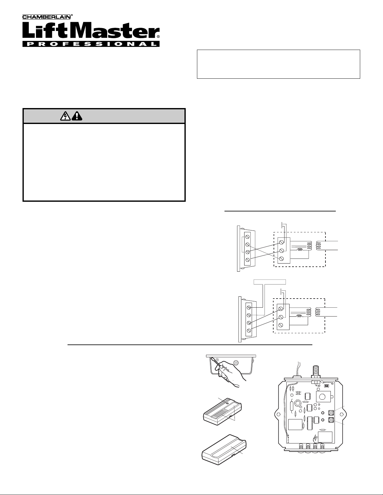
Use a screwdriver to pry open the receiver cover, Figure 3.
Re-connect power to the opener and the accessory
transformer, if used.
• Follow code switch remote control instructions, if applicable.
• Select a remote push button to operate opener #1.
• Press and hold the selected remote button. Then press and
release the “learn” button labeled “A” on the receiver. The
adjacent indicator light will FLASH.
•. Release the remote push button. Opener #1 will now operate
when the selected remote control push button is pressed.
Repeat the procedure, using “learn” button “B”, with the other
remote push button to program the second opener
Note: If a remote control push button is not pressed within
30 seconds, indicator light adjacent to selected "learn"
button will turn OFF. In that case, repeat the programming.
FOR SERVICE DIAL OUR TOLL FREE NUMBER:
1-800-528-2806
Figure 2
1
2
3
1
2
3
Receiver
(Bottom)
Operator
24 v
Trans
Primary
4
Common
Relay
Wall
Button
Figure 3
Figure 1
© 2005, The Chamberlain Group, Inc.
114A3133 All Rights Reserved Printed in Mexico
1
2
3
1
3
Receiver
(Bottom)
Wall
Button
Operator
24 v
Trans
Primary
4
Common
2
Relay
Transformer 95
AB
Learn
Button
"A"
Learn
Button
"B"
Garage door opener #1 (without transformer)
Refer to Figure 1 for wiring connections:
Connect 2-conductor bell wire (not provided) to receiver terminal
screws 3 and 4, and to the opener terminal screws used for the
wall push button.
Also, connect bell wire to receiver terminal 2 and opener
terminal screw 3; use a jumper wire to connect receiver
terminals 1 and 3.
Garage door opener #1 (with transformer 95)
Refer to Figure 2 for wiring connections:
Connect bell wire to receiver terminal screws 1 and 2, and to
transformer terminals. Also, connect bell wire (not provided) to
receiver terminal screws 3 and 4, and to opener terminal screws
used for wall push button.
Garage door opener #2: Connect white and white/red bell wire
from the receiver to the opener terminal screws used for the wall
button.
n
NOTICE: To comply with FCC and or Industry Canada rules (IC), adjustment or modifications of this
receiver and/or transmitter are prohibited, except for changing the code setting or replacing the
battery. THERE ARE NO OTHER USER SERVICEABLE PARTS.
Tested to Comply with FCC Standards FOR HOME OR OFFICE USE. Operation is subject to the
following two conditions: (1) this device may not cause harmful interference, and (2) this device
must accept any interference received, including interference that may cause undesired operation.
WARNING
RECEIVER
RED
Indicator
Light
Select a
Push Butto
Push
Button
 Loading...