

Page 1
OWNERS MANUAL
If power is other than shown in specifications,
Accessory Transformer Model 85 is required.
Accessory Transmitters
Series 50
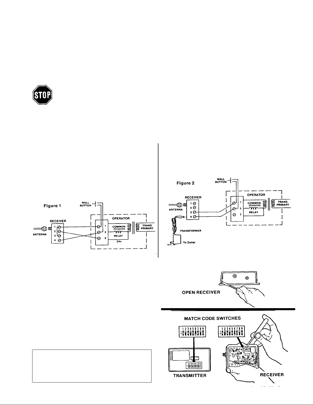
DISCONNECT POWER TO OPERATOR BEFORE INSTALLING RECEIVER OR SETTING/CHANGING CODE.
FIGURE 2 - WITH TRANSFORMER MODEL 85:
Receiver terminals 1 and 2 are not used. Connect bell
wire to receiver terminals 3 and 4 and to operator relay
control terminals 1 and 2. The transformer plugs into a
120V outlet
Printed in Mexico
______________________________________________________________________________________________________
Model 200 Lift- Master Universal Receiver
Manufactured under 1 or more of the following US patents:
3,445,848; 3,906,348; and 4,037,201
SPECIFICATIONS
Output Rating ..................3 Amps 120VAC or DC Max.
Power ..........................................18V to 35V, @ 30ma
RF Frequency ................................................. 390MHz
INSTALLATION INSTRUCTIONS
The receiver and antenna use TV Type F coaxial connectors. The antenna can be plugged directly onto the receiver, or
mounted to a bracket and connected to the receiver with Model 86 Coaxial Cable Kit, depending on your requirements.
Fasten receiver securely with screws through the two holes provided in the cover flanges. Select a location that allows
access to the terminals and space for the antenna (as far from metal structures as possible and preferably in a vertical
position).
FIGURE 1 - WITHOUT TRANSFORMER: Connect bell
wire (not supplied) to receiver terminals 1 and 2, and to
operator radio power terminals. (On operators with the
terminals labeled 1, 2 and 3, it will usually be 1 and 3).
All terminals are unpolarized.
Also, connect the bell wire to receiver terminal 4 and
operator terminal 2. Make a jumper wire connection to
receiver terminals 1 and 3 as shown.
___________________________________________________________________________________________________
SETTING THE CODE IN RECEIVER AND TRANSMITTER(S)
Pry open the receiver cover and locate the 9 code
switches. Open the transmitter case. With a screwdriver
or a pen, slide one or more of the receiver code
switches to a plus, center (0) or minus position. If
transmitter has 8 code switches, set receiver code
switch 9 to (0).
Hold transmitter circuit board alongside the receiver
switches. Set transmitter code switches to matching
positions. Reassemble the receiver and transmitter.
Reconnect power to the operator.
IMPORTANT: Code settings must be exactly the
same in receiver, transmitter and all additional
transmitters used to operate the device.
NO USER SERVICEABLE PARTS.
ACCESSORIES
Model 85 Transformer
114A1025C
Model 86 Coaxial Cable Kit
 Loading...