

Page 1
195LM Ceiling Mount
Garage Door Opener
Track
Down Rod
Bracket
Structural
Supports
Down Rod
Self-Tapping Bolt
5/16˝-18x1˝
Align the
channels
REAR VIEW
Bracket
Track
Structural
Supports
Structural
Support
Lag Screw
5/16˝-9x1-5/8˝
Lag Screw
5/16˝-9x1-5/8˝
Garage Door Opener
Garage Door Opener
OPTION 1
OPTION 2
OPTION 1
Serrated
Hex Flange Nut 5/16˝-18
Down Rod
Bolt 5/16˝-18x3-1/4˝
Slide Mechanism
Tighten nut to secure slide
mechanism to track
Track
Cut from
this end
One-Piece
Doors Only
4˝
X˝
X˝
Down Rod
OR
Wire
Management
Channel
Crown
Pan Head
Screw 6-19
Track
Down Rod
Hex Nut
5/16˝-18
Lock Washer 5/16˝
Hex Head Cap Screw
5/16˝-18x7/8˝
REAR VIEW
Bracket
To avoid possible SERIOUS INJURY from a falling garage door opener, fasten it SECURELY
to structural supports of the garage. Concrete anchors MUST be used if installing track into
masonry.
CARTON INVENTORY
Track
Down rod
Bracket
Crown (2)
Cover (for wire management)
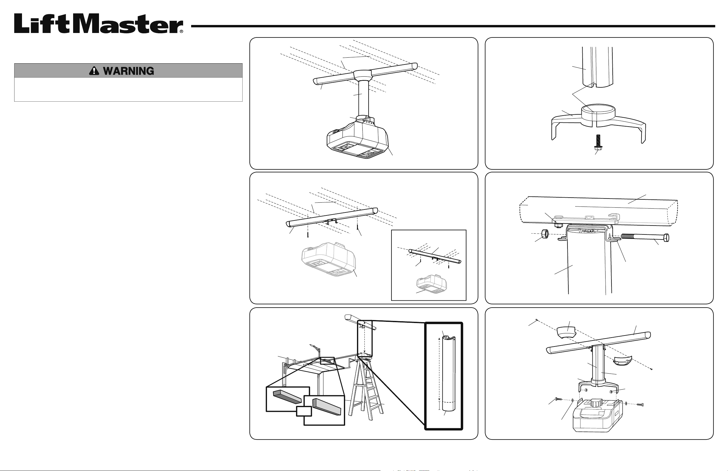
1. FASTEN THE TRACK TO THE CEILING (FIGURE 1)
Determine where the garage door opener will be installed. There are two option for installing the track:
• Option 1 (Recommended): Install track perpendicular to the garage door opener rail.
• Option 2: Install track parallel to the garage door opener rail.
The track MUST be RIGIDLY fastened to structural support on ceiling using lag screws.
NOTE: The down rod rotates +/-11 degrees only in the direction of the garage door. With option 2, the
garage door opener will sway more when operating and the track MUST be centered with the garage
door opener; no rotational adjustability left to right. Otherwise the garage door opener/rail may be at a
slight angle when the garage door opener is mounted.
Hardware bag: Lag screws 5/16"-9x1-5/8" (2),
bolt 5/16"-18x3-1/4", hex nut with serrated washer head 5/16"18, self-tapping bolt 5/16"-18x1", screws 5/16"-18x7/8" (2), lock
washers 5/16" (2), hex nuts 5/16"-18 (2),
and pan head screws 6-19 (2)
OVERVIEW
FIGURE 1
FIGURE 3
FIGURE 4
2. DETERMINE THE LENGTH OF THE DOWN ROD AND CUT TO LENGTH (FIGURE 2)
To determine the length of the down rod, measure the distance from the ceiling to the top of the garage
door opener, and then subtract 4". Cut the down rod using the template provided. DO NOT cut the end of
the down rod with the holes, cut from the other end. Use a fi le to remove burrs from cut end, especially
near the wire management channel.
NOTE: For best results use a power saw with a vise for cutting the down rod straight and to protect the
paint from chipping. A hack saw may be used but may not cut as straight and the paint will be more
prone to chipping.
3. ATTACH THE BRACKET TO THE DOWN ROD (FIGURE 3)
Attach the bracket to the down rod with the self-tapping bolt 5/16"-18 X 1" provided, tighten the bolt.
Ensure the bolt is fully seated and tightened. Make sure the wire management channel on the down rod
is aligned with wire management channel on the bracket.
4. ATTACH THE DOWN ROD TO THE SLIDE MECHANISM IN THE TRACK (FIGURE 4)
Insert the 5/16”-18 X 3-1/4” bolt through the slide mechanism and down rod and attach with the
serrated hex fl ange nut; this is for the pivot point of the kit. Move the slide mechanism along the track
until the down rod is in a vertical orientation and tighten hardware.
5. ATTACH THE BRACKET (WITH DOWN ROD) TO THE GARAGE DOOR OPENER (FIGURE 5)
Attach the bracket to the garage door opener with 5/16" lock washers, 5/16"-18 hex nuts, and 5/16"-18
X 7/8" hex head cap screws. Make sure the wire management channel is facing the power cord on the
garage door opener. Tighten at this point.
6. ROUTE WIRES THROUGH THE WIRE MANAGEMENT CHANNEL (FIGURE 5)
Route the power cord, safety reversing sensor wires and door control wires through the wire
management channel. Measure and cut cover for the wire management channel. Snap cover onto down
rod. Use a zip tie to secure all wires into one of the 4 holes in the slide mechanism.
7. COMPLETE INSTALLATION (FIGURE 5)
Secure the crown together with the pan head screws 6-19 (2) provided.
FIGURE 2 FIGURE 5
Page 2
Montage au plafond 195LM
Supports
structurels
Tige descendante
Rail
Support
Ouvre-porte de garage
VUE ARRIÈRE
Tige descendante
Support
Alignez les canaux
Boulon autotaraudeur de
5/16 po-18x1 po
Supports
structurels
Supports
structurels
Rail
Ouvre-porte de garage
Ouvre-porte de garage
Tire-fond de
5/16 de po-9x1-5/8 de po
Tire-fond de
5/16 po-9x1-5/8 de po
OPTION 2
OPTION 1
Rail
Tige descendante
Mécanisme coulissant
Serrez l’écrou pour fixer le
mécanisme coulissant au rail
Écrou hexagonal à épaulement
strié de 5/16 po-18
Boulon de 5/16 po-18x3-1/4 po
Coupez à partir
de cette extrémité
Tige descendante
Portes d’une seule
pièce seulement
OU
4 po
X po
X
po
Tige descendante
Couronne
Support
Rail
VUE ARRIÈRE
Vis d’assemblage à tête hexagonale
de 5/16 po-18x7/8 po
Écrou hexagonal
de 5/16 po-18
Canal de passage
des fils
Vis à tête cylindrique 6-19
Rondelle d’arrêt de 5/16 po
AVERTISSEMENT
Pour éviter d’éventuelles GRAVES BLESSURES dues à la chute de l’ouvre-porte de garage, fi xez-le SOLIDEMENT aux
supports structurels du garage. Des chevilles d’ancrage à béton DOIVENT être utilisées si le rail est installé sur un
ouvrage de maçonnerie.
INVENTAIRE DE LA BOÎTE
D’EMBALLAGE
Rail
Tige descendante
Support
Couronne (2)
Couvercle (pour canal de câblage)
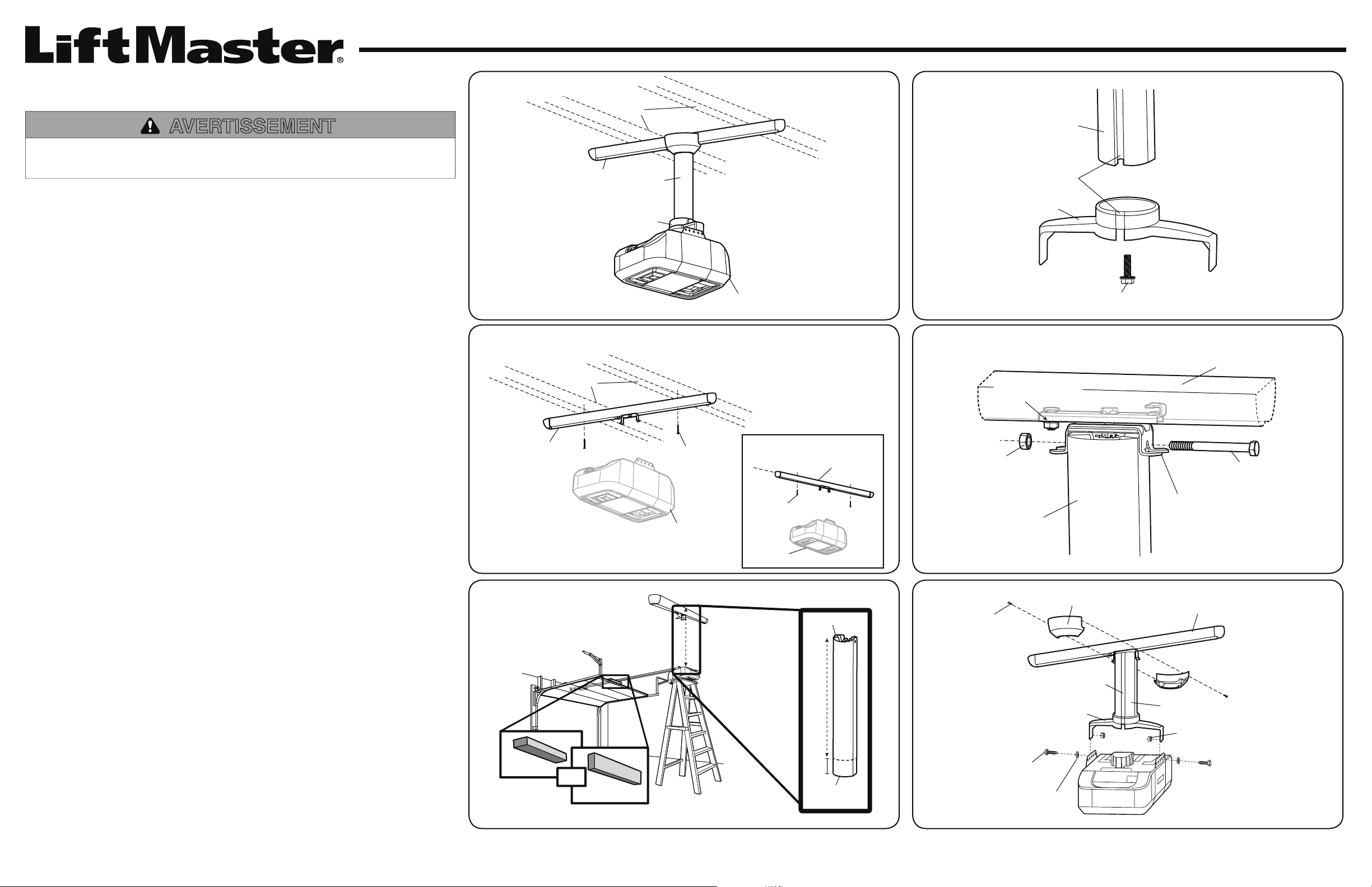
1. FIXEZ LE RAIL AU PLAFOND (FIGURE 1)
• Option 1 (recommandée) : Installez le rail perpendiculaire au rail de l’ouvre-porte de garage.
• Option 2 : Installez le rail parallèle au rail de l’ouvre-porte de garage.
Le rail DOIT être SOLIDEMENT fi xé à un support structurel au plafond à l’aide de tire-fonds.
REMARQUE : La tige descendante pivote de +/-11 degrés uniquement dans le sens de la porte de garage. Avec
l’option 2, l’ouvre-porte de garage se balancera davantage lors de l’utilisation et le rail DOIT être centré sur l’ouvreporte de garage; la rotation n’est pas ajustable de gauche à droite. Par contre, l’ensemble de rail/ouvre-porte de
garage peut être placé légèrement en angle lors du montage de l’ouvre-porte.
Sachet de pièces de quincaillerie : Tire-fond de 5/16 po-9x1-5/8 po (2),
boulon de 5/16 po-18x3-1/4 po, écrou hexagonal avec tête à rondelle striée
de 5/16 po-18, boulon autotaraudeur de 5/16 po-18x1 po, vis de 5/16 po18x7/8 po (2), rondelle d’arrêt de 5/16 po (2), écrou hexagonal de
5/16 po-18 (2) et vis à tête cylindrique 6-19 (2)
VUE D’ENSEMBLE
FIGURE 1
FIGURE 3
FIGURE 4
2. DÉTERMINEZ LA LONGUEUR NÉCESSAIRE DE LA TIGE DESCENDANTE
ET COUPEZ-LA (FIGURE 2)
Pour déterminer la longueur de la tige descendante, mesurez la distance entre le plafond et le dessus de l’ouvre-porte
de garage, puis soustrayez 10,2 cm (4 po). Coupez la tige descendante en utilisant le gabarit fourni. NE coupez PAS
l’extrémité de la tige percée de trous, mais bien l’autre extrémité. Enlevez les ébarbures de la coupe au moyen d’une
lime, particulièrement près du canal de passage des fi ls.
REMARQUE : Pour obtenir les meilleurs résultats, utilisez une scie électrique et un étau afi n de couper la tige en ligne
droite et protégez la peinture contre les éclats. Vous pouvez utiliser une scie à métaux mais la coupe ne sera pas aussi
droite et la peinture est plus susceptible de s’écailler.
3. FIXEZ LE SUPPORT À LA TIGE DESCENDANTE (FIGURE 3)
Fixez le support à la tige descendante avec le bouton autotaraudeur de 5/16 po-18 X 1 po fourni et serrez le boulon.
Assurez-vous que le boulon est complètement appuyé et bien serré. Assurez-vous que le canal de passage des fi ls de
la tige descendante est aligné avec le canal de passage des fi ls du support.
4. FIXEZ LA TIGE DESCENDANTE AU MÉCANISME COULISSANT DANS
LE RAIL (FIGURE 4)
Insérez le boulon de 5/16 po-18 X 3-1/4 po au travers du mécanisme coulissant et de la tige descendante et fi xez-le
avec l’écrou hexagonal à épaulement strié; ceci correspond au point de pivot de l’ensemble. Déplacez le mécanisme
coulissant le long du rail jusqu’à ce que la tige descendante soit à la verticale, puis serrez la quincaillerie.
5. FIXEZ LE SUPPORT (AVEC LA TIGE DESCENDANTE) À L’OUVRE-PORTE
DE GARAGE (FIGURE 5)
Fixez le support à l’ouvre-porte de garage avec les rondelles d’arrêt de 5/16 po, les écrous hexagonaux de 5/16 po-18
et les vis d’assemblage à tête hexagonale de 5/16 po-18X 7/8 po. Assurez-vous que le canal de passage des fi ls fait
face au cordon électrique de l’ouvre-porte de garage. Serrez ce point d’assemblage.
6. ACHEMINEZ LES FILS DANS LE CANAL DE PASSAGE (FIGURE 5)
Acheminez le cordon électrique, les fi ls du capteur d’inversion et les fi ls de la commande de la porte dans le canal
de passage des fi ls. Mesurez et coupez le couvercle du canal de passage des fi ls. Emboîtez le couvercle sur la tige
descendante. Fixez les fi ls à l’aide d’une attache dans l’un des quatre trous du mécanisme coulissant.
7. COMPLÉTEZ L’INSTALLATION (FIGURE 5)
Fixez la couronne avec les vis à tête cylindrique 6-19 (2) fournies.
FIGURE 2 FIGURE 5
Page 3

Montaje en techo 195LM
Soportes
estructurales
Barra de
bajada
Abre-puertas de garaje
Corredera
Soporte
Barra de bajada
Perno autorroscante de
5/16 de pulg.-18x1 pulg.
Alinear los canales
Soporte
VISTA TRASERA
Abre-puertas de garaje
Abre-puertas de garaje
Soportes
estructurales
Tornillos tirafondos
de 5/16 de pulg.9x1-5/8 de pulg.
Tornillos tirafondos de
5/16 de pulg.-9x1-5/8
de pulg.
Soportes
estructurales
Corredera
OPCIÓN 1
OPCIÓN 2
Barra de bajada
Tuerca de brida
hexagonal serrada
5/16 de pulg.-18
Perno de 5/16 de pulg.18x3-1/4 de pulg.
Apretar la tuerca para sujetar
el mecanismo deslizante
a la corredera
Corredera
Mecanismo deslizante
Puertas de una
pieza solamente
4 pulg.
X
pulg.
X
pulg.
O
Barra de bajada
Cortar desde
este extremo
Tornillos de cabeza
redondeada de 6-19
Arandela de
traba de 5/16
de pulg.
Barra de bajada
Tuercas hexagonales
de 5/16 de pulg.-18
Corona
Corredera
Soporte
Tornillo de cabeza
hexagonal de
5/16 de pulg.-18x7/8
de pulg.
Canal de
organización
de cables
VISTA TRASERA
ADVERTENCIA
Para evitar posibles LESIONES GRAVES debidas a la caída de un abridor de puertas de garaje, sujetarlo FIRMEMENTE
a soportes estructurales del garaje. Se DEBEN usar anclajes de hormigón si se instala la corredera en mampostería.
INVENTARIO DE LA
CAJA DE CARTON
Corredera
Barra de bajada
Soporte
Corona (2)
Cubierta (para organizar los cables)
1. SUJETAR LA CORREDERA AL TECHO (FIGURA 1)
Determinar dónde se instalará el abridor de la puerta del garaje. Hay dos opciones para instalar la corredera:
• Opción 1 (recomendada): Instalar la corredera perpendicular al carril del abridor.
• Opción 2: Instalar la corredera paralela al carril del abridor.
La corredera DEBE estar sujeta de forma RÍGIDA al soporte estructural del techo usando tornillos tirafondos.
NOTA: La barra de bajada +/-11 grados solamente en el sentido de la puerta del garaje. Con la opción 2, el abridor
oscilará más al operar y la corredera DEBE estar centrada con el abridor; sin capacidad de ajuste rotacional de
izquierda a derecha. De lo contrario, el abridor/carril debe estar ligeramente inclinado cuando esté montado el abridor.
Bolsa de herrajes: tornillos tirafondos de 5/16 de pulg.-9x1-5/8
de pulg. (2), perno de 5/16 de pulg.-18x3-1/4 de pulg., tuerca hexagonal
con cabeza de arandela serrada de 5/16 de pulg.-18, perno autorroscante
de 5/16 de pulg.-18x1 pulg., tornillos de 5/16 de pulg.-18x7/8 de pulg. (2),
arandelas de traba de 5/16 de pulg. (2), tuercas hexagonales de 5/16
de pulg.-18 (2) y tornillos de cabeza redondeada de 6-19 (2)
VISTA GENERAL
FIGURA 1
FIGURA 3
FIGURA 4
2. DETERMINAR LA LONGITUD DE LA BARRA DE BAJADA Y CORTAR A LA MEDIDA (FIGURA 2)
Para determinar la longitud de la barra de bajada, medir la distancia del techo a la parte superior del abridor, y
después restar 4 pulg. Cortar la barra de bajada con la plantilla suministrada. NO cortar el extremo de la barra de
bajada con los agujeros, cortar por el otro extremo. Usar una lima para quitar las rebabas del extremo cortado,
especialmente cerca del canal de organización de cables.
NOTA: Para obtener los mejores resultados usar una sierra eléctrica con una prensa para cortar la barra de bajada
recto y proteger la pintura contra las astilladuras. También se puede usar una segueta pero tal vez no corte tan recto y
la pintura tendrá más tendencia a astillarse.
3. SUJETAR EL SOPORTE A LA BARRA DE BAJADA (FIGURA 3)
Sujetar el soporte a la barra de bajada con el perno autorroscante 5/16 de pulg.-18 x 1 pulg. suministrado, apretar
el perno. Asegurarse de que el perno esté completamente asentado y apretado. Asegurarse de que el canal de
organización de cables en la barra de bajada esté alineado con el canal de organización de cables en el soporte.
4. SUJETAR LA BARRA DE BAJADA AL MECANISMO DESLIZANTE EN LA
CORREDERA (FIGURA 4)
Insertar el perno 5/16”-18 x 3-1/4 de pulg. por el mecanismo deslizante y barra de bajada y sujetar con la tuerca de
brida hexagonal serrada; esto es para el punto de pivote del juego. Mover el mecanismo deslizante a lo largo de la
corredera hasta la barra de bajada esté en una orientación vertical y apretar los herrajes.
5. SUJETAR EL SOPORTE (CON LA BARRA DE BAJADA) AL ABRIDOR (FIGURA 5)
Sujetar el soporte al abridor con arandelas de traba de 5/16 de pulg., tuercas hexagonales de 5/16 de pulg.-18 y
tornillos de cabeza hexagonal de 5/16 de pulg.-18x7/8 de pulg. Asegurarse de que el canal de organización de cables
apunte al cordón de alimentación en el abridor. Apretar ahora.
6. TENDER LOS CABLES POR EL CANAL DE ORGANIZACIÓN DE CABLES (FIGURA 5)
Tender el cordón de alimentación, los cables del sensor de inversión de seguridad y los cables de control de la
puerta por el canal de organización de cables. Medir y cortar la cubierta del canal de organización de cables. Encajar
la cubierta en la barra de bajada. Use una abrazadera para sujetar todos los cables en uno de los 4 agujeros del
mecanismo de deslizamiento.
7. COMPLETAR LA INSTALACIÓN (FIGURA 5)
Fijar la corona con los tornillos de cabeza redondeada 6-19 (2) suministrados.
FIGURA 2 FIGURA 5
Page 4

© 2013, The Chamberlain Group, Inc.
All Rights Reserved
Tous droits réservés
114A4559B Todos los Derechos Reservados
 Loading...