


MANUALE DI USO E MANUTENZIONE
MANUEL D’UTILISATION ET D’ENTRETIEN
USE AND MAINTENANCE MANUAL
PR Industrial S.r.l.
Località Il Piano, 53031 Casole d’Elsa (SI) - Italy
info@lifter.it
ANLEITUNG FÜR GEBRAUCH UND WARTUNG
MANUAL DE USO Y MANTENIMIENTO
INSTRUÇÕES DE UTILIZAÇAÕ E DE MANUTENÇAÕ
ADVIÉZEN VOOR GEBRIUK EN ONDERHOUD
BRUGERVEJLEDNING OG VEDLIGEHOLDELSESVEJLEDNING
BRUK-OG VEDLIKEHOLDSANVISNING
BRUKSANVISNING OCH SKÖTSEL
KÄYTTÖ-JA HUOLTO-OHJE
VANZI industria grafica - 03/2016 - 100 - REV. 00 - G009400
P
A
D
P
E
L
C
Y
C
E
R
%
0
0
1
R
E
R
1
0
0
%
R
E
C
Y
C
L
E
D
E
P
P
A
GX
GX
SOMMARIO (1.1)
Q kg 1200 1200 1200 1200 1200 1200 1200
c mm 600 600 600 600 600 600 600
x mm 780 780 780 780 780 780 780
y mm 1234 1234 1234 1234 1234 1234 1234
kg 530 545 578 570 585 618 615
kg 543/1187 558/1187 591/1187 583/1187 598/1187 631/1187 628/1187
kg 368/162 383/162 416/162 408/162 423/162 456/162 453/162
100x38 100x38 100x38 100x38 100x38 100x38 100x38
b
10
mm 565 565 565 565 565 565 565
b
11
mm 410 410 410 410 410 410 410
h
1
mm 1787 1987 2250 1787 1987 2250 1965
h
2
mm - - 80 - - 80 1402
h
3
mm 2410 2810 3410 2410 2810 3410 2810
h
4
mm 2992 3392 3916 2992 3392 3916 3372
h
5
mm - - - - - - -
h
14
mm 915/1310 915/1310 915/1310 960/1330 960/1330 960/1330 960/1330
h
13
mm 90 90 90 90 90 90 90
l
1
mm 1760 1760 1760 1760 1760 1760 1760
l
2
mm 609 609 609 609 609 609 609
b
1
mm 800 800 800 800 800 800 800
s/e/l mm 70/150/1150 70/150/1150 70/150/1150 70/150/1150 70/150/1150 70/150/1150 70/150/1150
b
3
mm 650 650 650 650 650 650 650
b
5
mm 560 560 560 560 560 560 560
m
2
mm 20 20 20 20 20 20 20
A
st
mm 2210 2210 2210 2210 2210 2210 2210
W
a
mm 1430 1430 1430 1430 1430 1430 1430
km/h 4,7/5,2 4,7/5,2 4,7/5,2 4,7/5,2 4,7/5,2 4,7/5,2 4,7/5,2
m/s 0,11/0,19 0,11/0,19 0,11/0,19 0,11/0,19 0,11/0,19 0,11/0,19 0,10/0,18
m/s 0,12/0,15 0,12/0,15 0,12/0,15 0,19/0,19 0,19/0,19 0,19/0,19 0,16/0,14
% 5/10 5/10 5/10 5/10 5/10 5/10 5/10
ELETTRICO ELETTRICO ELETTRICO ELETTRICO ELETTRICO ELETTRICO ELETTRICO
kW 0,7 0,7 0,7 0,7 0,7 0,7 0,7
kW 2,2 2,2 2,2 2,2 2,2 2,2 2,2
V/Ah 24/85 (C20) 24/85 (C20) 24/85 (C20) 24/118 (C5) 24/118 (C5) 24/118 (C5) 24/118 (C5)
kg 38 38 38 78 78 78 78
kWh/h 0,9 0,9 0,9 0,9 0,9 0,9 0,9
dB(A) 62 62 62 62 62 62 62
CARATTERISTICHE TECNICHE.......................................................pag.1
DICHIARAZIONE DI EMISSIONE VIBRATORIA................................pag.1
IMPIEGO DELLA MACCHINA ..........................................................pag.1
DESCRIZIONE DEL CARRELLO ......................................................pag.1
DISPOSITIVI DI SICUREZZA............................................................pag.1/2
TARGHETTE .....................................................................................pag.2
TRASPORTO E MESSA IN FUNZIONE............................................pag.2
BATTERIA.........................................................................................pag.2
USO..................................................................................................pag.2/3
MANUTENZIONI...............................................................................pag.3
RICERCA GUASTI............................................................................pag.4
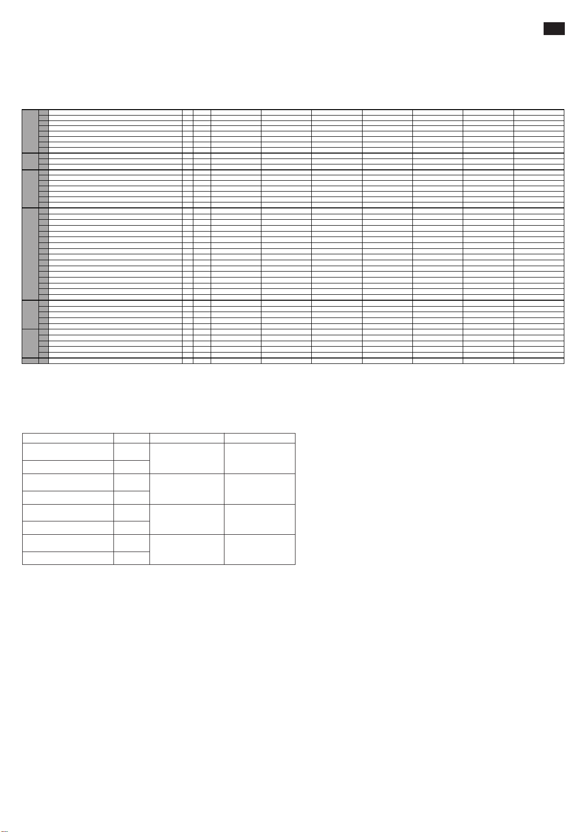
CARATTERISTICHE TECNICHE (3.46)
1.1 COSTRUTTORE PR INDUSTRIAL PR INDUSTRIAL PR INDUSTRIAL PR INDUSTRIAL PR INDUSTRIAL PR INDUSTRIAL PR INDUSTRIAL
1.2 MODELLO GX 12/25 III ED. BASIC GX 12/29 III ED. BASIC GX 12/35 III ED. BASIC GX 12/25 III ED. EVO GX 12/29 III ED. EVO GX 12/35 III ED. EVO GX 12/29 III ED. FL EVO
1.3 PROPULSIONE ELETTRICO ELETTRICO ELETTRICO ELETTRICO ELETTRICO ELETTRICO ELETTRICO
1.4 SISTEMA DI GUIDA ACCOMPAGNAMENTO ACCOMPAGNAMENTO ACCOMPAGNAMENTO ACCOMPAGNAMENTO ACCOMPAGNAMENTO ACCOMPAGNAMENTO ACCOMPAGNAMENTO
1.5 PORTATA
1.6 BARICENTRO
DESCRIZIONEPESITELAIO/RUOTE
1.8 DISTANZA ASSE RUOTE DI CARICO DA BASE FORCA
1.9 PASSO
2.1 MASSA IN SERVIZIO CON BATTERIA (VEDI RIGA 6.5)
2.2 CARICO SUGLI ASSI CON CARICO, ANTERIORE/POSTERIORE
2.3 CARICO SUGLI ASSI SENZA CARICO, ANTERIORE/POSTERIORE
3.1 GOMMATURA * G+P/P G+P/P G+P/P G+P/P G+P/P G+P/P G+P/P
3.2 DIMENSIONI RUOTE ANTERIORI (Ø x larghezza) 250x76 250x76 250x76 250x76 250x76 250x76 250x76
3.3 DIMENSIONI RUOTE POSTERIORI (Ø x larghezza) 82x70 82x70 82x70 82x70 82x70 82x70 82x70
3.4 DIMENSIONI RUOTE LATERALI (Ø x larghezza)
3.5 NUMERO DI RUOTE (x=MOTRICE) ANTERIORE/POSTERIORE 1x+1/2 1x+1/2 1x+1/2 1x+1/2 1x+1/2 1x+1/2 1x+1/2
3.6 CARREGGIATA ANTERIORE
3.7 CARREGGIATA POSTERIORE
4.2 ALTEZZA, MONTANTE CHIUSO
4.3 ALZATA LIBERA
4.4 ALTEZZA DI SOLLEVAMENTO
4.5 ALTEZZA, MONTANTE SFILATO
4.6 ALZATA INIZIALE
4.9 ALTEZZA DEL TIMONE IN POSIZIONE DI GUIDA MIN/MAX
4.15 ALTEZZA FORCHE ABBASSATE
4.19 LUNGHEZZA TOTALE
4.20 LUNGHEZZA UNITÁ MOTRICE
4.21 LARGHEZZA TOTALE
4.22 DIMENSIONI FORCHE
4.24 LARGHEZZA FRONTALE FORCHE
4.25 LARGHEZZA FORCHE
4.32 LUCE LIBERA A METÁ PASSO
4.34 CORRIDOIO DI STIVAGGIO PER PALLET 800x1200 LONGITUDINALMENTE
4.35 RAGGIO DI VOLTA
5.1 VELOCITÁ DI TRASLAZIONE, CON/SENZA CARICO
5.2 VELOCITÁ DI SOLLEVAMENTO, CON/SENZA CARICO
5.3 VELOCITÁ DI DISCESA, CON/SENZA CARICO
5.8 PENDENZA SUPERABILE, CON/SENZA CARICO
5.10 FRENO DI SERVIZIO
PRESTAZIONI DIMENSIONI
6.1 POTENZA MOTORE DI TRAZIONE
6.2 POTENZA MOTORE DI SOLLEVAMENTO
6.4 TENSIONE BATTERIA, CAPACITÁ NOMINALE C5
6.5 MASSA BATTERIA
MOTORI
ELETTRICI
6.6 CONSUMO DI ENERGIA SECONDO CICLO VDI
8.4 RUMOROSITÁ ALL'ORECCHIO DELL'OPERATORE
*G=Gomma, P=Poliuretano, N=Nylon
IT
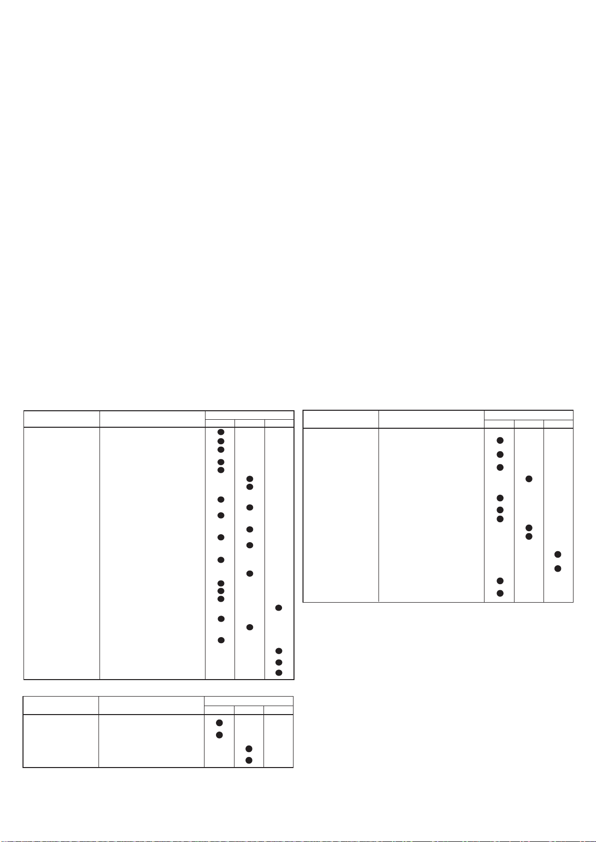
DICHIARAZIONE DI EMISSIONE VIBRATORIA (33.2)
Valori di emissione vibratoria dichiarati conformemente alla EN 12096
Superficie di provaDescrizione Valore Norma Europea (EN)
Valore di emissione vibratoria
misurato, a (m/s
2
)
Incertezza, K (m/s2)
Valore di emissione vibratoria
misurato, a (m/s
2
)
Incertezza, K (m/s2)
Valore di emissione vibratoria
misurato, a (m/s2)
Incertezza, K (m/s2)
Valore di emissione vibratoria
misurato, a (m/s
2
)
Incertezza, K (m/s2)
0.71
0.68
2.3
0.6
0.77
0.39
1.02
0.08
EN ISO 20643
(Mano-Braccio)
EN ISO 20643
(Mano-Braccio)
EN 13059
(Corpo intero)
EN 13059
(Corpo intero)
Pavimento in cemento
liscio industriale
Su pista di prova
secondo EN 13059
Pavimento in cemento
liscio industriale
Su pista di prova
secondo EN 13059
Valori determinati in conformità con la EN ISO 20643 e la EN 13059.
IMPIEGO DELLA MACCHINA (4.1)
Questa macchina è stata progettata per il sollevamento ed il trasporto di unità di carico su pavimenti lisci e senza alcuna asperità. Sullo chassis si trova una targhetta di identificazione che indica la
capacità di sollevamento che non dovrà mai essere superata per la sicurezza del personale e per non danneggiare il veicolo. Si consiglia di rispettare rigorosamente le norme antinfortunistiche e quelle
riguardanti il funzionamento e la manutenzione. Qualsiasi montaggio di attrezzature accessorie sulla macchina dovrà essere autorizzata dalla CASA COSTRUTTRICE.
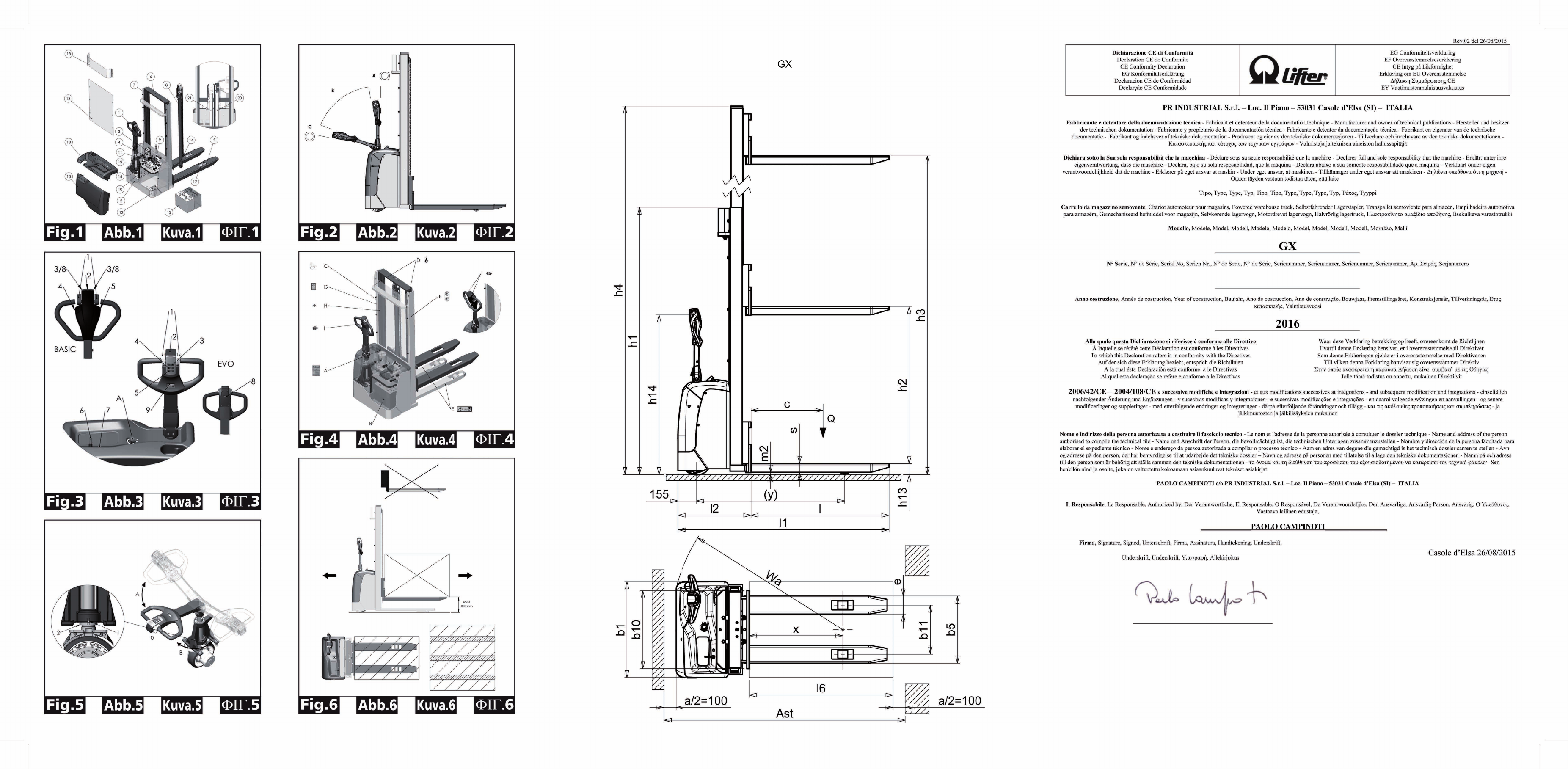
DESCRIZIONE DEL CARRELLO (5.16)
Questo carrello è un elevatore elettrico a forche con guida a timone, ideale per lo stoccaggio e il trasporto di unità di carico su percorsi piani e privi di asperità. Gli organi di comando sono ben visibili
e azionabili comodamente. L’elevatore è conforme a tutte le norme attuali di conforto e sicurezza C.E. Il disegno mostra le principali caratteristiche:
1. TIMONE DI GUIDA 2. MOTORUOTA 3. CENTRALINA IDRAULICA 4. SBLOCCO MANUALE FORCHE 5. FORCA SOLLEVAMENTO 6. SECONDO STADIO 7. TELAIO 8. CILINDRO
SOLLEVAMENTO 9. INTERRUTTORE GENERALE 10. SCHEDA ELETTRONICA CONTROLLO FORCA (EVO) 11. SCHEDA ELETTRONICA 12. RUOTA STABILIZZATRICE 13. CARTER
14. VALVOLA PARACADUTE 15. BATTERIA 16. ELETTROFRENO 17. RULLI DI CARICO 18. PROTEZIONE MANI 19. CARICA BATTERIE 20. CILINDRO SOLLEVAMENTO FORCA (solo versione
Free Lift) 21. CILINDRO SOLLEVAMENTO SECONDO STADIO (solo versione Free Lift)
DISPOSITIVI DI SICUREZZA (6.12) (vedi fig.1)
1. INTERRUTTORE GENERALE (RIF.9) 2. ELETTROFRENO (RIF.16) 3. VALVOLA PARACADUTE (RIF.14) 4. VALVOLA DI MASSIMA PRESSIONE 5. PROTEZIONE PARAURTI: servono a
proteggere dagli urti la ruota motrice (RIF.2), le ruote laterali stabilizzatrici (RIF.12) ed i rulli di carico anteriori (RIF.17); in caso di incidente quindi i piedi ed il carico sono salvaguardati. 6. TASTATORE
“UOMO MORTO” (RIF.2/FIG.3): è un interruttore di sicurezza situato sul timone di guida e protegge il conduttore contro le collisioni in marcia indietro 7. PROTEZIONE MANI (RIF.18) 8. DISPOSITIVO
PER SBLOCCO MANUALE DELLE FORCHE (RIF.4)
Struttura (7.10)
Il montante di sollevamento con le gambe e il cofano formano una struttura saldata molto rigida (rif.7/fig.1). Le forche sono guidate con precisione da 4 rulli che scorrono su tutta l’altezza del montante.
La ruota di trazione, una ruota pivottante e due rulli assicurano al carrello una grande stabilità su 4 punti di appoggio.
I carter (rif.13/fig.1) facilmente apribili consentono una buona accessibilità a tutti i gruppi per il servizio assistenza.
Trazione (8.4)
Il gruppo di trazione aziona la ruota motrice tramite ingranaggi conici e cilindrici. Il senso di marcia si inverte azionando le farfalle poste sul timone di guida (rif.1/fig.3).
Timone (9.12) (rif.1/fig.1)
Il carrello può essere guidato da un conduttore a piedi. L’angolo di sterzata è di 210°.
Il timone agisce direttamente sulla ruota motrice quindi per cambiare direzione bisogna ruotarlo nel senso desiderato. Per azionare il carrello (vedi fig.2) si deve tenere il timone nella posizione centrale
(pos.B), mentre per fermarlo lo si deve portare nella posizione superiore (pos.A) o in quella inferiore (pos.C). Una volta rilasciato il timone ritorna automaticamente nella posizione superiore (pos.A) e
fa ufficio di freno di parcheggio. In modalità “tartaruga”, quando il timone è nella posizione superiore (pos.A) o in quella inferiore (pos.C), premendo il tasto “tartaruga” (rif.8, fig.3) ed agendo sul regolatore
di marcia (rif.1, fig.3), il carrello si muove a velocità ridotta.
1
Freni (10.7)
La frenatura di servizio viene effettuata dal motore, rilasciando l’acceleratore. Il freno elettromagnetico fa ufficio di freno di stazionamento e freno di emergenza. La frenatura di emergenza si effettua
portando il timone alla posizione superiore (pos.A) o alla posizione inferiore (pos.C) (vedi fig.2). Se si disinserisce l’impianto elettrico, il freno elettromagnetico agisce come freno di stazionamento.
Impianto idraulico (11.11)
Per sollevare e abbassare le forche è sufficiente agire sui pulsanti di comando (rif.4.5/fig.3) del gruppo timone in modo che la motopompa (rif.3/fig.1) mandi l’olio idraulico dal serbatoio al cilindro di
sollevamento. L’energia necessaria al lavoro effettivo è fornita dalla batteria (rif.15/fig.1). In caso di guasti al sistema elettrico o di esaurimento dell’energia stoccata nella batteria mentre il carrello ha le
forche sollevate, è possibile farle scendere per spostare il carrello agendo sul sistema di sblocco manuale (RIF.4/FIG.1) installato sull’elettrovalvola.
Nell’impianto idraulico sono installate due valvole di sicurezza:
a) Valvola paracadute, evita che il carico cada improvvisamente in caso di rottura del sistema idraulico ed è integrata nel cilindro.
b) Valvola di massima pressione integrata nella motopompa, protegge il sistema meccanico e idraulico dai sovraccarichi.
Impianto elettrico (12.9)
Costruito secondo le norme in vigore è costituito da un variatore elettronico (rif.11/fig.1) programmabile (dotato di tutte le sicurezze e regolazioni) e da organi di
comando azionabili dalla testata del timone. Le connessioni sono assicurate contro l’allentamento accidentale. I conduttori sono in rame, molto flessibili ed hanno
la sezione adatta alle condizioni di funzionamento ed alle influenze esterne che possono verificarsi.
Tutti i componenti elettrici sono montati in modo da assicurare il funzionamento e facilitare la manutenzione.
TARGHETTE (13.13) (vedi fig.4)
Sulla macchina sono visibili le seguenti targhette: A) Targhetta di identificazione del tipo di veicolo; B) Targhetta batteria; C) Targhetta diagramma di carico in
funzione dell’altezza di sollevamento e posizione del baricentro di carico delle forche; D) Targhette indicanti i punti di imbracatura; E) Targhette pericolo schiacciamento
piedi; F) Targhette divieti d’uso; G) Targhetta leggere manuale; H) Targhetta indicante l’altezza a cui si trova approssimativamente la forca sollevata. I) Targhetta
pulsante “tartaruga”
NB: Le targhette non devono assolutamente essere rimosse o rese illeggibili.
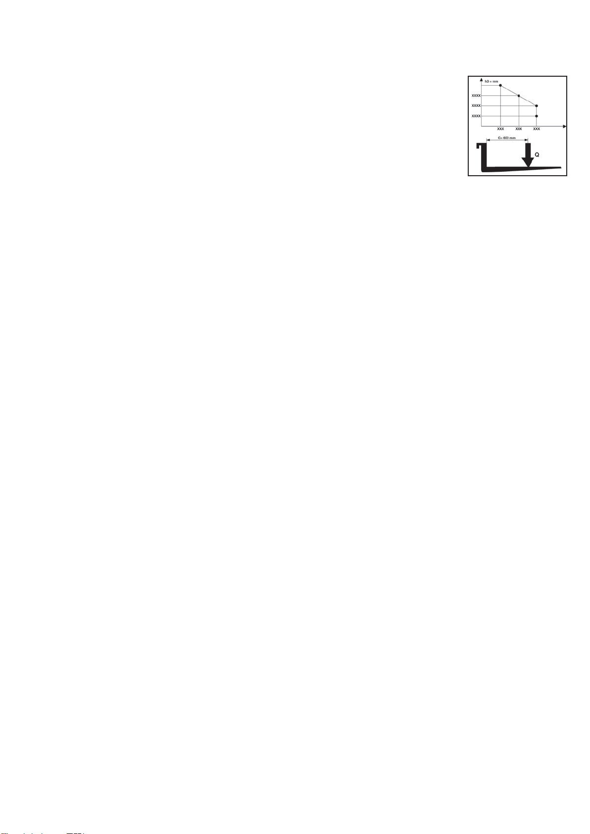
IMPORTANTE: E’ PROIBITO ECCEDERE LA PORTATA FISSATA SULLA TARGHETTA TIPO “C” ATTACCATA ALLA MACCHINA ALL’ATTO DI VENDITA E QUI DI SEGUITO RIPORTATA.
NB: Il presente diagramma illustra il rapporto tra il carico massimo sollevabile e la relativa altezza massima da terra nelle operazioni di carico e scarico di un pallet da uno scaffale.
NB: Lo schema della forca schematizzata qui di fianco indica la posizione del baricentro del carico che però deve essere distribuito più uniformemente possibile su tutta la lunghezza
della forca stessa!!
TRASPORTO E MESSA IN FUNZIONE
Trasporto (14.10)
Per trasportare il carrello sono previsti due punti di imbracatura indicati dalle targhette “D” (fig.4), mentre il peso della macchina è indicato sulla targhetta di identificazione “A” (fig.4). Prima dell’imbracatura
si raccomanda di rimuovere la protezione mani superiore (Rif.18, fig.1) per evitarne la rottura. Rimontare la protezione prima della messa in funzione della macchina. E’ buona norma, durante il trasporto,
assicurare saldamente il carrello in modo che non possa capovolgersi. Verificare che dalla batteria (se presente) non fuoriescano acido o vapori.
Messa in funzione (15.1)
Prima di mettere in funzione la macchina controllare che tutte le parti siano in perfette condizioni, verificare il funzionamento di tutti i gruppi e l'integrità dei dispositivi di sicurezza. Spostare il carrello
con la corrente di batteria e mai con la corrente alternata raddrizzata per non danneggiare i componenti elettrici.
BATTERIA (16.7)
Istruzioni, misure di sicurezza e manutenzione
L’ispezione, la carica e il cambio della batteria deve essere fatto da personale autorizzato seguendo le istruzioni d’uso del costruttore della stessa. E’ vietato fumare e tenere vicino al carrello e
all’apparecchio di carica materiale infiammabile o che provoca scintille. L’ambiente deve essere ben arieggiato. Per una buona manutenzione i tappi degli elementi devono essere asciutti e puliti.
Eliminare l’acido fuoriuscito, spalmare un po’ di vaselina sui morsetti e stringerli. Il peso e le dimensioni della batteria possono influire sulla stabilità del carrello quindi se viene montata una batteria
diversa da quelle standard si consiglia di interpellare la CASA COSTRUTTRICE per la necessaria autorizzazione. Il carrello monta un indicatore di stato batteria che si accende all’accensione della
macchina. In caso di inattività della macchina questo si spegne automaticamente e si riaccende al suo nuovo utilizzo. Il led verde indica che le batterie sono sufficientemente cariche. Quando il livello
di carica comincia a diventare insufficiente si accende la luce gialla, indicando una carica ancora sufficiente solo per alcuni cicli di lavoro. Quando la carica residua raggiunge un livello inferiore al 20%
si accende la luce rossa. In questa condizione non è più possibile sollevare il carico ma la macchina può ancora traslare per raggiungere la presa di corrente per la ricarica. L’indicatore si attiva anche
durante la fase di ricarica per indicarne lo stato di avanzamento.
Carica della batteria
Prima di iniziare la carica verificare l’integrità dei conduttori. Collegare la spina del carica batterie (A) alla rete (vedi fig.3). A fine carica il caricabatterie interrompe l’erogazione di corrente illuminando
la spia verde. Staccare la spina (A) dalla rete. Una ricarica normale richiede dalle 10 alle 12 ore. E’ preferibile ricaricare la batteria alla fine delle ore di utilizzo del carrello. Il caricabatterie è concepito
per assicurare una carica di mantenimento per un certo tempo dopo la carica completa. Non esiste il rischio di sovraccarica quindi non è necessario staccare il caricabatterie dopo la totale ricarica.
NB: non scaricare mai completamente le batterie, ed evitare le cariche incomplete; inoltre lasciare sempre che sia il caricabatterie a segnalare il termine della carica.
ATTENZIONE: scaricare eccessivamente le batterie significa ridurgli la vita.
Cambio della batteria (17.4)
a) Rimuovere il cofano posteriore; b) Sbloccare la batteria dai fermi; c) Staccare i cavi dai poli della batteria; d) Estrarre la batteria; e) Rimontare la batteria secondo l’ordine inverso, fissandola nella
propria sede e collegandola correttamente.
NB: mettere sempre una batteria dello stesso tipo di quella sostituita.
IMPORTANTE: IMPIEGARE CON CURA L’ACIDO SOLFORICO, E’ TOSSICO E CORROSIVO; ATTACCA LA PELLE E I VESTITI CHE EVENTUALMENTE DOVRANNO ESSERE LAVATI CON
SAPONE E ACQUA ABBONDANTE. IN CASO DI INCIDENTE CONSULTARE UN MEDICO!!!
NB: nel caso di sostituzione della batteria consegnare la vecchia al centro di raccolta più vicino.
Verifica batteria
Leggere attentamente le istruzioni di uso e manutenzione del costruttore della batteria. Verificare l’assenza di corrosione, la presenza di vaselina e che l’acido arrivi 15mm sopra le placche. Se gli
elementi sono scoperti rabboccare con acqua distillata. Misurare la densità dell’elettrolita con un densimetro per controllare il livello di carica.
USO (18.17)
Il guidatore dovrà svolgere le seguenti istruzioni d’uso nella posizione di guida; dovrà cioè compiere le operazioni in modo da rimanere ragionevolmente lontano dalle zone pericolose per lo schiacciamento
di mani e/o piedi, quali montanti, forche, catene, pulegge, ruote motrici e stabilizzatrici e qualsiasi altro organo in movimento.
Norme di sicurezza
Il carrello deve essere utilizzato conformemente alle seguenti norme:
a) Il conducente della macchina deve essere adeguatamente formato, conoscere le istruzioni d’uso relative al veicolo, indossare indumenti adatti e portare il casco.
b) Il conducente, responsabile del carrello, deve impedire ai non addetti la guida del mezzo ed evitare che estranei salgano sulle forche.
c) Durante la guida l’operatore deve regolare la velocità in curva, in passaggi stretti, porte o su pavimento irregolare. Deve allontanare dalla zona dove il carrello si muove i non
addetti ed avvisare immediatamente se ci sono persone in pericolo; nel caso nonostante l’avvertimento ci sia ancora qualcuno nella zona di lavoro il conducente è tenuto a fermare
subito il carrello.
d) E’ proibito soffermarsi nelle zone in cui ci siano parti in movimento e salire sulle parti fisse del carrello.
e) Il conducente deve evitare le fermate brusche e le inversioni di marcia veloci.
f) In caso di salita o discesa, con pendenza max consentita, il conducente deve tenere il carico a monte e ridurre la velocità.
g) Durante la guida il conducente deve fare attenzione ad avere una buona visibilità ed avere lo spazio libero durante la retromarcia.
h) Se il carrello viene trasportato su ascensori deve entrare con le forche di carico davanti (accertarsi prima che l’ascensore abbia la portata sufficiente).
i) E’ assolutamente proibito mettere fuori servizio o smontare i dispositivi di sicurezza. Se il carrello lavora in ambienti ad alto rischio d’incendi o di esplosione, questo deve essere
approvato per un tale tipo di utilizzazione
j) La capacità di sollevamento del carrello non può in alcun caso essere superata. Il conducente deve assicurarsi che il carico sia ben sistemato sulle forche ed in perfetto ordine;
non sporgere mai oltre le estremità di queste più di 50mm.
k) E’ vietato movimentare il carrello con le forche in posizione alta, è consentito solo nelle manovre necessarie a depositare o prelevare unità di carico.
l) Prima di iniziare il lavoro il conducente del carrello dovrà controllare:
• il funzionamento del freno di servizio e di stazionamento;
• che le forche di carico siano in perfette condizioni
• le ruote e i rulli siano integri;
• la batteria sia carica, ben fissata e gli elementi ben asciutti e puliti;
• che tutti i dispositivi di sicurezza siano funzionanti;
m) Interrompere l’utilizzo del carrello qualora lo stato della batteria (rif.7/fig.3) segnali circa il 20% di carica disponibile e porlo in ricarica.
n) Il carrello deve essere sempre adoperato o parcheggiato al riparo da pioggia, neve e comunque non deve essere impiegato in zone molto umide.
o) Temperatura di utilizzo -10°/40°C
p) Evitare l’utilizzo del carrello per il traino di rimorchi o di altri carrelli
q) Segnalare immediatamente eventuali danni, guasti o malfunzionamenti al personale responsabile. È vietato l’uso del carrello fino alla sua riparazione
r) Il conducente se sprovvisto della necessaria qualifica non è autorizzato ad effettuare riparazioni sul carrello e non gli è consentito disattivare o modificare i dispositivi di sicurezza
e gli interruttori
2
NB: LA CASA COSTRUTTRICE NON SI ACCOLLA NESSUN ONERE RELATIVO A GUASTI O INFORTUNI DOVUTI AD INCURIA, INCAPACITA’, INSTALLAZIONE DA PARTE DI TECNICI NON
ABILITATI ED UTILIZZO IMPROPRIO DEL CARRELLO.
Traslare
Prima di muovere il carrello controllare il funzionamento dell’avvisatore acustico, del freno e che la batteria sia carica completamente. Girare la chiave in posizione 1 e portare il timone in posizione di
traslazione. Girare il regolatore lentamente e dirigersi nella direzione di lavoro desiderata. Per frenare o fermarsi completamente girare il regolatore nel senso contrario a quello di marcia. Con il carrello
sterzare sempre delicatamente in quanto movimenti bruschi sono causa di situazioni pericolose (in particolar modo quando il carrello si muove ad alta velocità). Spostarsi sempre con il carico in
posizione bassa, ridurre la velocità nelle strettoie e quando si curva.
Impilare
1) Muoversi attentamente vicino alla scaffalatura con il carico in posizione bassa. 2) Essere sicuri che le gambe del carrello abbiano un passaggio libero sotto il pallet o nella scaffalatura. Il modo
migliore è di mettere in perfetta linea il lato del pallet da sollevare con quello ultimo nello scaffale prendendolo come riferimento. In questo modo il lavoro di impilamento e di scarico sarà più facile.
3) Sollevare il carico fino a che esso superi liberamente il livello del piano di stoccaggio. 4) Muoversi lentamente in avanti e fermarsi quando il carico è sopra lo scaffale; a questo punto abbassare le
forche in modo da liberarle dal pallet e da non forzare sopra il ripiano sottostante. Controllare che il carico sia sicuramente posizionato. 5) Muoversi lentamente indietro facendo attenzione che il pallet
rimanga ben impilato. 6) Abbassare le forche nella posizione di traslazione (fig.6).
Scaricare
1) Con le forche in posizione bassa e perpendicolare avvicinarsi allo scaffale ed entrare sotto l’ultimo pallet 2) Tornare con le forche fuori dal pallet 3) Sollevare le forche all’altezza desiderata e lentamente
muoversi verso il pallet da scaricare. Nello stesso tempo guardare che le forche entrino sotto il pallet senza difficoltà e che il carico sia posizionato con sicurezza sulle forche. 4) Sollevare le forche fino a
sollevare il pallet dal livello del ripiano 5) Muoversi lentamente indietro nel corridoio 6) Abbassare il carico lentamente e nello stesso tempo guardare che le forche non trovino ostacoli durante la discesa
Modalità di uso a velocità ridotta (“Tartaruga”)
Per l’utilizzo in spazi angusti oppure per movimentare con precisione e sicurezza merci delicate, è possibile ricorrere all’uso in modalità “tartaruga”. La modalità tartaruga è utilizzabile solo con il timone di
comando completamente sollevato. Per le operazioni in modalità a velocità ridotta tenere premuto il tasto apposito (rif.8/fig.3) su cui è riportato il pittogramma di una tartaruga e agire sui comandi per la
traslazione e il movimento delle forche come fatto nelle operazioni in modalità standard.
ATTENZIONE: Confrontare sempre il peso del carico con la capacità di sollevamento relativa all’altezza indicata sull’apposita targhetta.
ATTENZIONE: Quando il carico è sollevato i movimenti di sterzatura e frenatura devono essere fatti lentamente e con molta attenzione.
Blocco del sollevamento (28.2)
La macchina è dotata di un dispositivo automatico che blocca il sollevamento se le batterie raggiungono un livello di scarica superiore all’80%.
L’intervento del dispositivo è segnalato dal led rosso dell’indicatore stato batteria.
Se tale dispositivo interviene è necessario portare il carrello alla zona di ricarica e procedere come descritto al paragrafo “Carica delle batterie”.
Organi di comando (19.13) (fig. 3)
1) Regolatore di marcia 2) Tastatore “uomo morto” 3) Tasto segnalatore acustico 4) Tasto sollevamento 5) Tasto discesa 6) Interruttore generale 7) Segnalatore stato batteria 8) Tasto “tartaruga”
(velocità ridotta) 9) Display segnalatore stato batteria e contaore
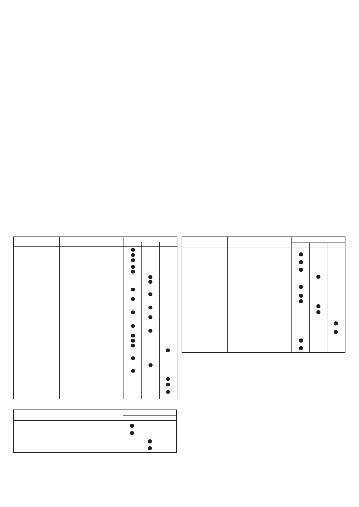
MANUTENZIONE (20.14)
La manutenzione deve essere effettuata da personale specializzato. Il carrello deve essere sottoposto almeno una volta l'anno ad un controllo generale. Dopo ogni manutenzione
deve essere verificato il funzionamento del carrello e dei dispositivi disicurezza. Sottoporre il carrello a periodiche ispezioni per non incorrere in fermi macchina o in pericoli per il
personale! (vedi tabella manutenzione).
Tabella manutenzione
ELEMENTO CONTROLLI
STRUTTURA E FORCA
FRENI
RUOTE
TIMONE
SISTEMA ELETTRICO
SISTEMA IDRAULICO
Tabella di lubrificazione
PUNTI
DI LUBRIFICAZIONE
RUOTE E RULLI
CATENA
DI SOLLEVAMENTO
GUIDE MONTANTI
GRUPPO IDRAULICO
Verifica elementi portanti
Verifica serraggio bulloni e viti
Controllo battute e giochi forca
Verifica funzionamento
Verifica usura ferodo
Verifica potenza di frenatura
Verifica del gioco (circa 0,4 mm)
Verifica usura
Verifica gioco cuscinetti
Verifica ancoraggio
Verifica del gioco
Verifica movimento laterale
Verifica ritorno posiz. verticale
Verifica usura dei teleruttori
Verifica connessioni, guasti di cavi
Verifica interruttore generale
Verifica avvisatore acustico
Verifica tastatore "uomo morto"
Verifica valori fusibili
Verifica funzionamento
Verifica livello olio
Verifica delle perdite e usura
connessioni
Cambiare olio/filtro
Verifica funzionamento valvola
limitatrice di pressione
Verifica valvola limitatrice
di flusso
DI LUBRIFICANTE
Grasso al Litio NLGI-2
Grasso al Litio NLGI-2
Grasso al Litio NLGI-2
Olio ISO VG 32
TIPO
SCADENZA
3 MESI 6 MESI 12 MESI
SCADENZA
3 MESI 6 MESI 12 MESI
ELEMENTO CONTROLLI
CILINDRO
MOTORI ELETTRICI
BATTERIA
ISPEZIONI
Regolazione altezza ruota motrice (Fig. 5)
Regolare l’altezza della ruota motrice secondo la seguente procedura per
compensarne l'usura:
1) Smontare il carter inferiore;
2) Con il timone in posizione “0” inserire un cacciavite nel foro del distanziale rif.1
e ruotare il timone in direzione “A” (1/4 di giro = 0,5 mm di sfilamento della ruota
motrice);
3) Sfilare il cacciavite e ruotare il timone in direzione “B” fino a tornare in posizione
“0”;
4) Ripetere le operazioni ai punti 2 e 3 quante volte necessario (Nel caso in cui
la ruota motrice risultasse troppo sfilata ripetere le operazione 2 e 3 ruotando in
senso opposto);
5) Serrare la ghiera rif.2 contro il distanziale Rif.1 e rimontare il carter inferiore.
N.B. Sostituire la ruota prima che lo spessore del battistrada sia inferiore a 5
mm.
Verifica funzionamento perdite
e usura guarnizioni
Controllo pulegge
Verifica usura spazzole
Verifica relais di avviamento
motore
Verifica densità e livello elettrolita
(non necessario su batterie gel)
Controllo tensione elementi
Verifica ancoraggio e tenuta morsetti
Verifica integrità cavi
Ingrassare morsetti con vaselina
Verifica collegamento a massa
impianto elettrico
Verifica velocità di traslazione
salita e discesa forche carico
Verifica dispositivi di sicurezza
Prova sollevamento e discesa
con carico nominale
SCADENZA
3 MESI 6 MESI 12 MESI
N.B. - Usare olio idraulico escluso olio motore e freni.
Nota: disfarsi dell'olio usato rispettando l'ambiente. Si consiglia l'accumulo in fusti
da consegnarsi successivamente al centro di raccolta più vicino. Non scaricare l'olio
in terra o in luoghi non adatti.
PULIZIA DEL CARRELLO: pulire le parti del carrello, ad esclusione di quelle elettriche ed
elettroniche con uno straccio umido. Non lavare assolutamente con getti d'acqua diretta,
vapore e liquidi infiammabili. Pulire le parti elettriche ed elettroniche con aria compressa
deumidificata a bassa pressione (max 5 bar), oppure con un pennello non metallico.
3
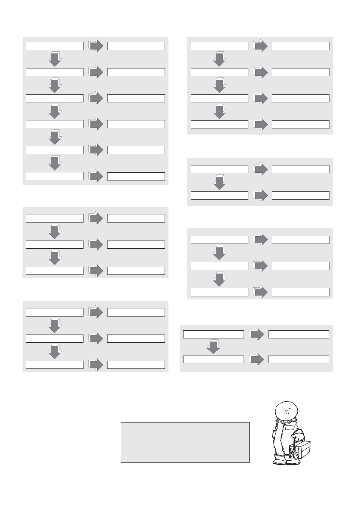
RICERCA GUASTI
LA MACCHINA NON PARTE (21.2)
BATTERIA SCARICA CARICARE BATTERIA
NO
MICRO TIMONE ROTTO SOSTITUIRE
NO
FUSIBILE DI POTENZA BRUCIATO
NO
FUSIBILE AUSILIARIO BRUCIATO SOSTITUIRE
NO
CHIAVE ROTTA MONTARE NUOVA CHIAVE
NO
CORTO CIRCUITO IMPIANTO
ELETTRICO
SI
SI
SI
SOSTITUIRE
SI
SI
SI
CONTROLLARE IMPIANTO
ELETTRICO
LA FORCHE NON RESTANO ALZATE (26.1)
LA FORCHE NON SOLLEVANO (22.1)
PERDITA DI OLIO NEL
SISTEMA IDRAULICO
SI
NO
SOVRACCARICO
SI
NO
BATTERIA SCARICA CARICARE BATTERIA
SI
NO
MANCA L’OLIO NEL SERBATOIO AGGIUNGERE OLIO
SI
VERIFICA CONNESSIONI
DIMINUIRE IL CARICO
IL CARRELLO NON FRENA (23.1)
BASSA COPPIA FRENANTE REGISTRARE IL FRENO
NO
GUASTO NEL SISTEMA FRENANTE
SI
SI
SOSTITUIRE FRENO
PERDITA DI OLIO NEL
CIRCUITO IDRAULICO
SI
VERIFICA CONNESSIONI
NO
VALVOLA DI PRESSIONE SPORCA
SI
PULIRE LA VALVOLA
NO
GUARNIZIONI CILINDRO USURATE
SI
CAMBIARE GUARNIZIONI
LA MOTOPOMPA NON PARTE (24.1)
SPAZZOLE MOTORE USURATE SOSTITUIRE
NO
SWITCH AVVIAMENTO ROTTO SOSTITUIRE
NO
COLLEGAMENTI ELETTRICI
DIFETTOSI
SI
SI
SI
VERIFICA COLLEGAMENTI
E GUARNIZIONI
LA BATTERIA NON SI CARICA
IL CARICABATTERIE NON É
COLLEGATO CORRETTAMENTE
(25.1):
SI
NO
FUSIBILE CARICABATTERIE ROTTO
SI
NO
FUSIBILE RETE PRINCIPALE ROTTO
SI
LA RUOTA MOTRICE SLITTA (34.2):
ALTEZZA RUOTA MOTRICE
NON CORRETTA
NO
RUOTA MOTRICE USURATA
SI
SI
EFFETTUARE REGOLAZIONE
SOSTITUIRE ANELLO RUOTA MOTRICE
VERIFICA CONNESSIONI
SOSTITUIRE
SOSTITUIRE
ATTENZIONE !!!
SE NESSUNA DELLE SOLUZIONI SUGGERITE
RISOLVE IL GUASTO PORTARE IL CARRELLO
ALL'ASSISTENZA PIU' VICINA
4

SOMMAIRE (1.1)
1.1 CONSTRUCTEUR PR INDUSTRIAL PR INDUSTRIAL PR INDUSTRIAL PR INDUSTRIAL PR INDUSTRIAL PR INDUSTRIAL PR INDUSTRIAL
Q kg 1200 1200 1200 1200 1200 1200 1200
c mm 600 600 600 600 600 600 600
x mm 780 780 780 780 780 780 780
y mm 1234 1234 1234 1234 1234 1234 1234
kg 530 545 578 570 585 618 615
kg 543/1187 558/1187 591/1187 583/1187 598/1187 631/1187 628/1187
kg 368/162 383/162 416/162 408/162 423/162 456/162 453/162
b
10
mm 565 565 565 565 565 565 565
b
11
mm 410 410 410 410 410 410 410
h
1
mm 1787 1987 2250 1787 1987 2250 1965
h
2
mm - - 80 - - 80 1402
h
3
mm 2410 2810 3410 2410 2810 3410 2810
h
4
mm 2992 3392 3916 2992 3392 3916 3372
h
5
mm - - - - - - -
h
14
mm 915/1310 915/1310 915/1310 960/1330 960/1330 960/1330 960/1330
h
13
mm 90 90 90 90 90 90 90
l
1
mm 1760 1760 1760 1760 1760 1760 1760
l
2
mm 609 609 609 609 609 609 609
b
1
mm 800 800 800 800 800 800 800
s/e/l mm 70/150/1150 70/150/1150 70/150/1150 70/150/1150 70/150/1150 70/150/1150 70/150/1150
b
3
mm 650 650 650 650 650 650 650
b
5
mm 560 560 560 560 560 560 560
m
2
mm 20 20 20 20 20 20 20
A
st
mm 2210 2210 2210 2210 2210 2210 2210
W
a
mm 1430 1430 1430 1430 1430 1430 1430
km/h 4,7/5,2 4,7/5,2 4,7/5,2 4,7/5,2 4,7/5,2 4,7/5,2 4,7/5,2
m/s 0,11/0,19 0,11/0,19 0,11/0,19 0,11/0,19 0,11/0,19 0,11/0,19 0,10/0,18
m/s 0,12/0,15 0,12/0,15 0,12/0,15 0,19/0,19 0,19/0,19 0,19/0,19 0,16/0,14
% 5/10 5/10 5/10 5/10 5/10 5/10 5/10
kW 0,7 0,7 0,7 0,7 0,7 0,7 0,7
kW 2,2 2,2 2,2 2,2 2,2 2,2 2,2
V/Ah 24/85 (C20) 24/85 (C20) 24/85 (C20) 24/118 (C5) 24/118 (C5) 24/118 (C5) 24/118 (C5)
kg 38 38 38 78 78 78 78
kWh/h 0,9 0,9 0,9 0,9 0,9 0,9 0,9
dB(A) 62 62 62 62 62 62 62
*G=Pneu, P=Polyuréthane, N=Nylon
CARACTERISTIQUES TECHNIQUES ............................................pag.5
DECLARATION DE L'EMISSION VIBRATOIRE ..............................pag.5
EMPLOI DE LA MACHINE...............................................................pag.5
DESCRIPTION DU CHARIOT..........................................................pag.5
NORMES DE SÉCURITÉ.................................................................pag.5/6
PLAQUETTES..................................................................................pag.6
TRANSPORT ET MISE EN FONCTION ..........................................pag.6
BATTERIE........................................................................................pag.6
UTILISATION....................................................................................pag.6/7
ENTRETIEN .....................................................................................pag.7
RECHERCHE DES PANNES...........................................................pag.8
CARACTERISTIQUES TECNIQUES (3.46)
1.2 MODÈLE GX 12/25 III ED. BASIC GX 12/29 III ED. BASIC GX 12/35 III ED. BASIC GX 12/25 III ED. EVO GX 12/29 III ED. EVO GX 12/35 III ED. EVO GX 12/29 III ED. FL EVO
1.3 ENTRAÎNEMENT ELECTRIQUE ELECTRIQUE ELECTRIQUE ELECTRIQUE ELECTRIQUE ELECTRIQUE ELECTRIQUE
1.4 FONCTIONNEMENT ACCOMPAGNANT ACCOMPAGNANT ACCOMPAGNANT ACCOMPAGNANT ACCOMPAGNANT ACCOMPAGNANT ACCOMPAGNANT
1.5 CAPACITÉ DE CHARGE
1.6 CENTRE DE GRAVITÉ
DESCRIPTIONPOIDSCHÂSSIS/ROUESDIMENSIONS
1.8 DISTANCE DE CHARGE DEPUIS LA BASE FOURCHE
1.9 EMPATTEMENT
2.1 MASSE EN SERVICE AVEC BATTERIE (voir ligne 6,5)
2.2 CHARGE PAR ESSIEU CHARGÉ, AVANT/ARRIÈRE
2.3 CHARGE PAR ESSIEU À VIDE, AVANT/ARRIÈRE
3.1 PNEUS * G+P/P G+P/P G+P/P G+P/P G+P/P G+P/P G+P/P
3.2 DIMENSIONS ROUES AVANT (Ø x largeur) 250x76 250x76 250x76 250x76 250x76 250x76 250x76
3.3 DIMENSIONS ROUES ARRIÈRE (Ø x largeur) 82x70 82x70 82x70 82x70 82x70 82x70 82x70
3.4 DIMENSIONS ROUES LATÉRALES (Ø x largeur) 100x38 100x38 100x38 100x38 100x38 100x38 100x38
3.5 NOMBRE DE ROUES (x=MOTRICE) AVANT/ARRIÈRE 1x+1/2 1x+1/2 1x+1/2 1x+1/2 1x+1/2 1x+1/2 1x+1/2
3.6 LARGEUR DE LA VOIE AVANT
3.7 LARGEUR DE LA VOIE ARRIÈRE
4.2 HAUTEUR, MÂT FERMÉ
4.3 HAUTEUR LIBRE
4.4 HAUTEUR DE LEVAGE
4.5 HAUTEUR, MÂT OUVERT
4.6 HAUTEUR INITIALE
4.9 HAUTEUR DU TIMON EN POSITION DE CONDUITE MIN/MAX
4.15 HAUTEUR FOURCHES EN POSITION BASSE
4.19 LONGUEUR TOTALE
4.20 LONGUEUR AVEC ARRIÈRE DE LA FOURCHE
4.21 LARGEUR TOTALE
4.22 DIMENSIONS FOURCHES
4.24 LARGEUR FRONTALE FOURCHES
4.25 LARGEUR FOURCHES
4.32 DÉGAGEMENT AU CENTRE DE L’EMPATTEMENT
4.34 ALLÉE DE TRAVAIL POUR PALETTES 800x1200 LONGITUDINAL
4.35 RAYON DE BRAQUAGE
5.1 VITESSE DE TRANSLATION, AVEC/SANS CHARGE
5.2 VITESSE DE LEVAGE, AVEC/SANS CHARGE
5.3 VITESSE DE DESCENTE, AVEC/SANS CHARGE
5.8 PENTE SURMONTABLE, AVEC/SANS CHARGE
5.10 FREIN DE SERVICE ELECTRIQUE ELECTRIQUE ELECTRIQUE ELECTRIQUE ELECTRIQUE ELECTRIQUE ELECTRIQUE
PERFORMANCES
6.1 PUISSANCE MOTEUR DE TRACTION
6.2 PUISSANCE MOTEUR DE LEVAGE
6.4 TENSION BATTERIE, CAPACITÉ NOMINALE
6.5 MASSE BATTERIE
MOTEURS
ÉLECTRIQUES
6.6 CONSOMMATION D'ENERGIE SELON CYCLE VDI
8.4 NIVEAU SONORE À L’OREILLE DU CONDUCTEUR
FR
DECLARATION DE L'EMISSION VIBRATOIRE (33.2)
Valeurs d'émission vibratoire déclarées conformément à EN 12096
Valeur d'émission vibratoire
mesurée, a (m/s2)
Incertitude, K (m/s
Valeur d'émission vibratoire
mesurée, a (m/s
Incertitude, K (m/s
Valeur d'émission vibratoire
mesurée, a (m/s2)
Incertitude, K (m/s
Valeur d'émission vibratoire
mesurée, a (m/s
Incertitude, K (m/s
2
)
2
)
2
)
2
)
2
)
2
)
Règle Européenne (EN)
0.71
0.68
2.3
0.6
0.77
0.39
1.02
0.08
EN ISO 20643
(Main-Bras)
EN ISO 20643
(Main-Bras)
EN 13059
(Corps entier)
EN 13059
(Corps entier)
Surface d'essaiDescription Valeur
Plancher en ciment
lisse industriel
Sur piste d'essai
selon EN 13059
Plancher en ciment
lisse industriel
Sur piste d'essai
selon EN 13059
Valeurs déterminées conformément à EN ISO 20643 et EN 13059.
EMPLOI DE LA MACHINE (4.1)
Cette machine a été projetée pour soulever et pour transporter des unités de charge sur des sols lisses et sans aucune aspérité. Sur le châssis on trouve une plaquette d’identification qui indique la capacité
de soulèvement qui ne devra jamais être dépassée pour la sécurité du personnel et pour ne pas endommager le véhicule. Il est conseillé de respecter rigoureusement les normes anti-accidents et celles
qui concernent le fonctionnement et l’entretien. N’importe quel montage d’équipements accessoires sur la machine devra être autorisé par la maison de construction.
DESCRIPTION DU CHARIOT (5.16) (voir fig.1)
Les organes de commande sont bien visibles et on peut les actionner facilement. L'élévateur est conforme à toutes les normes actuelles de confort et de sécurité CE. Le dessin montre les principales
caractéristiques:
1) GOUVERNAIL DE GUIDE 2) MOTOROUE 3) PETITE CENTRALE HYDRAULIQUE 4) DISPOSITIF MANUAL POUR DÉVERROUILLER LES FOURCHES 5) FOURCHE SOULEVEMENT 6) SECOND
STADE 7) CHASSIS 8) CYLINDRE SOULEVEMENT 9) INTERRUPTEUR GÉNÉRAL 10) CARTE ELECTRONIQUE CONTROLE FOURCHE (EVO) 11) FICHE ÉLECTRONIQUE 12) ROUE STABILISATRICE
13) CARTER 14) VALVE PARACHUTE 15) BATTERIE 16) ELECTROFREIN 17) ROULEAUX DE CHARGE 18) PROTECTION MAINS 19) REDRESSEUR 20) VERIN D LEVAGE FOURCHE (uniquement
version Free Lift) 21) VERIN DE LEVAGE SECOND STADE (uniquement version Free Lift)
DISPOSITIFS DE SÉCURITÉ (6.12) (voir fig.1)
1) INTERRUPTEUR GÉNÉRAL (ref.9) 2) ELECTROFREIN (ref.16) 3) VALVE POUR LIMITER LE FLUX (ref.14) 4) VALVE DE PROTECTION MAXIMUM 5) PROTECTIONS CONTRE LES CHOCS:
elles servent à protéger la roue motrice (réf. 2) des chocs, ainsi que les roues latérales stabilisatrices (réf. 12) et les rouleaux de charge antérieurs (réf. 17); en cas d'accident les pieds et la charge sont
donc sauvegardés. 6) TATEUR "HOMME MORT' (ref.2/fig.3): c'est un interrupteur de sécurité situé sur le gouvernail de guide et il protège le conducteur des collisions en marche arrière. 7) PROTECTION
MAINS (réf.18). 8) DISPOSITIF MANUAL POUR DÉVERROUILLER LES FOURCHES (réf. 4)
Structure (7.10) (voir fig.1)
Le montant de soulèvement avec les jambes et le coffre forment une structure soudée très rigide (ref. 7). Les fourches sont guidées avec précision par 4 rouleaux qui se déplacent sur toute la hauteur du
montant. La roue d'entraînement, la roue pivotante et deux rouleaux assurent au chariot une grande stabilité sur 4 points d'appui. Les carters (ref. 13) s'ouvrent facilement et permettent d'avoir un bon
accès à tous les groupes pour le service assistance.
Traction (8.4)
Le groupe de traction actionne la roue motrice au moyen d'engrenages coniques et cylindriques. Le sens de marche s'inverse en actionnant les papillons placées sur le gouvernail de guide(ref.1/fig.3).
Gouvernail (9.12) (ref.1 fig.1)
Le chariot peut être guidé par un conducteur à pieds. L’angle de braquage est de 210°. Le gouvernail agit directement sur la roue motrice et donc pour changer de direction, il faut le faire tourner dans le
sens désiré. Pour actionner le chariot (voir fig.2) il faut maintenir le gouvernail dans la position centrale (pos.B), tandis que pour l’arrêter on doit le mettre dans la position supérieure (pos.A) ou inférieure
(pos.C). Une fois que le gouvernail est laissé il retourne automatiquement dans la position supérieure (pos.A) et il sert de frein de parking. En mode “tortue”, lorsque le timon se trouve en position supérieure
(pos.A) ou inférieure (pos.C), pour déplacer le chariot à vitesse réduite, il suffit de pousser sur le bouton touche “tortue” (réf.8, fig.3) et d’agir sur l’interrupteur de freinage (réf.1, fig.3).
5

Frein (10.7)
Le freinage de service est effectué par le moteur, lorsqu’on relâche l’accélérateur. Le frein électromagnétique sert de frein de stationnement et de frein de secours. Le freinage de secours s’effectue en
portant le timon en position supérieure (pos. A) ou bien inférieure (pos. C) (voir fig. 2). En déconnectant l’équipement électrique, le frein électromagnétique sert de frein de stationnement.
Installation hydraulique (11.11)
Pour soulever et abaisser les fourches il est suffisant d’agir sur le levier de commande du groupe gouvernail (ref.4,5/fig.3) de façon à ce que la motopompe (ref.3/fig.1) envoie l’huile hydraulique du réservoir
vers le cylindre de soulèvement. L’énergie nécessaire au travail effectif est fournie par la batterie (ref.15/fig.1).
Dans le cas d'une défaillance du système électrique ou l'épuisement de l'énergie stockée dans la batterie alors que le chariot a soulevé fourches, vous pouvez les faire descendre pour déplacer le chariot
en appuyant sur le système de déverrouillage manuel (RIF.4/FIG.1) installé sur le solénoïde.
Dans l’installation hydraulique deux valves de sécurité sont installées:
a) Valve parachute, évite que la charge tombe à l’improviste en cas de rupture du système hydraulique et elle est intégrée dans le vérin de levage
b) Valve de pression maximum intégrée dans la motopompe, protège le système mécanique et hydraulique en cas de surcharge.
Installation électrique (12.9)
Construite selon les normes en vigueur et constituée d’un variateur électronique (ref.11/fig.1)) programmable (doté de toutes les sécurités et de tous les réglages) et
d’organes de commande actionnables à partir de la tête du gouvernail. Les connexions sont assurées contre le relâchement accidentel. Les conducteurs sont en
cuivre et sont très flexibles avec une section adaptée aux conditions de fonctionnement et aux influences externes qui peuvent se vérifier. Tous les composants
électriques sont montés de façon à assurer le fonctionnement et faciliter l’entretien.
PLAQUETTES (13.13) (voir fig. 4)
Sur la machine sont visibles les plaquettes suivantes: A) Plaquette d'identification du type de véhicule B) Plaquette batterie C) Plaquette diagramme de charge
en fonction de la hauteur de soulèvement et position du barycentre de charge des fourches D) Plaquettes indiquant les points d'élingage E) Plaquettes danger
écrasement pieds F) Plaquette défense d'usage G) Plaquette: lire les instructions H) Plaquettes indiquant la hauteur à laquelle est approximativement la fourche
soulevées. I) Plaquette bouton ‘tortue”
Les plaquettes ne doive absolument pas être enlevées ou être illisibles.
IMPORTANT: IL EST INTERDIT D'EXCEDER LA PORTEE FIXEE SUR LA PLAQUETTE TYPE C ATTACHÉE A LA MACHINE AU MOMENT DE L'ACTE DE VENTRE ET REPORTÉE Cl-DESSOUS:
Ce diagramme illustre le rapport entre la charge maximum que l'on peut soulever et la relative hauteur maximum par rapport à la terre dans les opérations de chargement et déchargement
d'une palette à partir d'un rayon.
Le schéma de la fourche représenté à côté indique la position du barycentre de la charge qui doit être, cependant, distribuée le plus uniformément possible sur toute la longueur de la
fourche-même!!
TRANSPORT ET MISE EN MARCHE
Transport (14.10)
Pour transporter le chariot deux points d'élingage sont prévus et sont indiqués sur les plaquettes type "D" (fig.4), tandis que le poids est indiqué sur la plaquette d'identification type "A" (fig.4).
Avant l’élingage, il est recommandé d’enlever le protection supérieure des mains (Rep.18, fig.1) pour éviter qu’elle ne se casse. On remontera ensuite cette protection avant de mettre la machine en service.
Pendant le transport il est conseillé de bien fixer le chariot pour qu’il ne se renverse pas. Vérifier qu’aucune fuite d’acide ou de vapeurs ne sort de la batterie (si présente).
Mise en marche (15.1)
Avant de mettre en marche la machine contrôler que toutes les parties sont en parfaite condition, vérifier le fonctionnement de tous les groupes et l'intégrité des dispositifs de sécurité. Déplacer le chariot
avec le courant de la batterie et jamais avec le courant alterné relevé pour ne pas endommager les composants électriques.
BATTERIE (16.7)
Instructions, mesures de sécurité et entretien
L'inspection, la charge et le changement de batterie doit être fait par un personnel autorisé en suivant les instructions d'utilisation du constructeur de celle-ci. Il est interdit de fumer et de laisser à côté du chariot
et de l'appareil de charge des matériaux inflammables ou qui provoquent des scintilles. Le milieu doit être bien aéré. Pour un bon entretien les bouchons des éléments doivent être secs et propres. Éliminer l'acide
qui sort, appliquer un peu de vaseline sur les bornes et les serrer. Le poids et les dimensions de la batterie peuvent influer sur la stabilité du chariot et donc si l'on monte une batterie différente des batteries
standard il est conseillé d'interpeller la MAISON DE CONSTRUCTION pour une autorisation nécessaire.
Le chariot monte un indicateur de l’état de la batterie qui s’allume à la mise sous tension de la machine. Lorsque la machine est inactive, celui-ci s’éteint automatiquement pour se rallumer lorsqu’on utilise de
nouveau la machine. La Del verte indique que les batteries sont suffisamment chargées. Quand le niveau de la charge commence à devenir insuffisant, la lampe jaune s’allume pour indiquer que la charge suffit
uniquement pour encore quelques cycles de travail. Lorsque la charge restante atteint un niveau inférieur à 20% de la charge totale, la lampe rouge s’allume. A ce stade, il n’est plus possible de soulever le
chargement mais on peut encore manœuvrer la machine pour atteindre la prise de courant où se produira la recharge. L’indicateur est également activé pendant la phase de recharge, afin d’indiquer l’état d’avancée
de celle-ci.
Rechargement de la batterie
Avant de commencer le rechargement vérifier que les conducteurs sont intègres. Relier la prise du chargeur de batterie (A) au secteur (voir fig.3). Au terme de la recharge, le chargeur de batterie
coupe le débit du courant et le voyant vert s'allume. A ce stade, on détachera la prise (A) du secteur. Une recharge normale suppose de 10 à 12 heures. Il est préférable de recharger la batterie au
terme des heures d'utilisation du chariot. Le recharge-batteries est conçu pour assurer un rechargement d'entretien pour un certain temps après le rechargement complet. Le risque de surcharge
n'existe pas et donc il n'est pas nécessaire de détacher le recharge-batteries après le rechargement total.
Ne jamais décharger complètement les batteries, et éviter les rechargements incomplets; en outre toujours laisser le recharge-batteries signaler la fin de la recharge.
ATTENTION: Décharger excessivement les batteries signifie leur réduire la vie!
Changement de la batterie (17.4)
a) Déposer le capot arrière; b) Détacher les câbles des pôles de la batterie; c) Extraire la batterie; d) Installer à nouveau la batterie de la façon inverse, en la plaçant dans son logement et en la connectant
correctement.
(toujours mettre une batterie du même type de celle que l’on change).
IMPORTANT: EMPLOYER AVEC SOIN L’ACIDE SULFURIQUE, IL EST TOXIQUE ET CORROSIF; IL ATTAQUE LA PEAU ET LES HABITS QUI DEVRONT ÉVENTUELLEMENT ETRE LAVES AVEC DU
SAVON ET DE L’EAU ABONDANTE. EN CAS D’INCIDENT CONSULTER UN MÉDECIN!!!
Si on remplace la batterie, on remettra l’ancienne au centre de collecte le plus proche.
Vérification batterie
Lire attentivement les instructions d’utilisation et d’entretien du Constructeur de la batterie. Vérifier l’absence de corrosion, la présence de vaseline sur les pôles et que l’acide arrive à 15 mm au-dessus
des plaques. Si les éléments sont découverts, remplir avec de l’eau distillée. Mesurer la densité de l’électrolyte avec un densimètre pour contrôler le niveau de charge.
UTILISATION (18.17)
Le conducteur devrà dérouler le mode d’emploi suivant dans la position de conduction; ça pour rester loin des zones dangereuses (comme les montants, les fourches, les chaînes, les poulies, les
roues motrices et stabilisatrices et tous les organes en mouvement), qui impliquent l’écrasement des mains et/ou des pieds.
Normes de sécurité
Le chariot doit être utilisé conformément aux normes suivantes:
a) Le conducteur de la machine aura reçu une formation adéquate, il connaîtra le mode d’emploi du véhicule, il portera les vêtements de sécurité appropriés et son casque de travail.
b) Le conducteur, responsable du chariot, doit empêcher à ceux qui ne sont pas autorisés la conduite du moyen et éviter que des personnes externes sautent sur les fourches ou sur l'estrade.
c) Durant la conduite l'opérateur doit régler la vitesse dans les virages, dans les passages étroits, dans les portes ou sur des sols irréguliers. Il doit éloigner de la zone où le chariot bouge ceux qui sont
étrangers aux travaux et aviser immédiatement s'il y a des personnes en danger; au cas où malgré l'avertissement il y aurait encore quelqu'un dans la zone de travail le conducteur est tenu d'arrêter
immédiatement le chariot.
d) Il est interdit de s'arrêter dans les zones ou il y a des parties en mouvement et de monter sur les parties fixes du chariot.
e) Le conducteur doit éviter les arrêts brusques et les inversions de marche rapides.
f) Dans des cas de montée ou de descente, avec une pente maximum consentie, le conducteur doit tenir la charge en haut et réduire la vitesse
g) Durant la conduite le conducteur doit faire attention à avoir une bonne visibilité et à avoir un espace libre pour faire marche arrière.
h) Si le chariot est transporté sur les ascenseurs il doit entrer avec les fourches de chargement devant (s'assurer avant que l'ascenseur a une portée suffisante)
i) Il est absolument interdit de mettre hors service ou de démonter les dispositifs de sécurité. Si le chariot travaille dans des milieux à haut risque d'incendie ou d'explosion, il doit être approuvé pour
un certain type d'utilisation.
j) La capacité de soulèvement du chariot ne peut en aucun cas être dépassée. Le conducteur doit s'assurer que le chariot est bien arrangé sur les fourches et en parfait ordre; ne jamais dépasser hors
des extrémités de plus de 50mm.
k) C'est interdit de faire bouger le chariot avec les fourches en position haute, il est consenti seulement durant les manœuvres nécessaires pour déposer ou pour prélever des unités de charge
l) Avant de commencer le travail le conducteur du chariot devra contrôler:
- le fonctionnement du frein de service et de stationnement
- que les fourches de charge soient en parfaite condition
- les roues et les rouleaux sont intègres
- la batterie est rechargée, bien fixée et les éléments bien secs et propres
- que tous les dispositifs de sécurité fonctionnent.
m) Interrompre l'utilisation du chariot lorsque le signal de la batterie (réf. 7/fig. 3) marque environ 20% de charge disponible, et le mettre en recharge.
n) Le chariot doit toujours être utilisé ou parqué à l'abri de la pluie, de la neige et ne doit pas être employé dans des zones très humides.
o) Température d'utilisation -10°, +400.
p) On évitera d’utiliser le chariot pour tirer des remorques ou d’autres chariots.
q) On signalera immédiatement les dégâts éventuels, pannes ou défaillances au personnel responsable. L’utilisation du chariot est interdite jusqu’à sa réparation.
r) S’il n’a pas la qualification requise, le conducteur n’est pas autorisé à effectuer les réparations sur le chariot et il ne lui est pas permis de désactiver ou de modifier les dispositifs de sécurité et les
interrupteurs.
6
LA MAISON DE CONSTRUCTION N'EST RESPONSABLE D'AUCUNE DÉPENSE RELATIVE À DES DÉGÂTS OU À DES ACCIDENTS DUS À UN MANQUE DE SOIN, Ô L'INCAPACITÉ, À UNE
INSTALLATION FAITE PAR DES TECHNICIENS NON HABILITÉS, ET À UNE UTILISATION IMPROPRE DU CHARIOT.
Transférer
Avant de bouger le chariot contrôler le fonctionnement de l'avertisseur acoustique, du frein et que la batterie soit complètement rechargée. Tourner la clé dans la position 1 et mettre le gouvernail en position
de translation. Tourner le régulateur lentement et se diriger dans la direction de travail désirée. Pour freiner ou pour s'arrêter complètement tourner le régulateur dans le sens contraire à celui de la marche.
Avec le chariot braquer toujours délicatement car les mouvements brusques sont causes de situations dangereuses (de façon particulière quand le chariot bouge à grande vitesse). Se déplacer toujours
avec la charge en position basse, réduire la vitesse dans les espaces étroits et quand on tourne.
Empiler
1) Bouger avec soin auprès des étagères avec la charge en position basse. 2) Etre sûrs que les pieds du chariot aient un passage libre sous la palette ou dans l'étagère. La meilleure façon est de mettre
de façon parfaitement alignée le côté de la palette à soulever avec le dernier dans l'étagère en le prenant comme référence. De cette fa9on le travail d'empilement et de décharge sera plus facile.
3) Soulever la charge jusqu'à ce qu'elle dépasse librement le niveau du plan de stockage. 4) Bouger lentement en avant et s'arrêter quand la charge est sur l'étagère; à ce moment-là abaisser les fourches
de façon à les libérer de la palette et à ne pas forcer sur la console qui est en dessous. Contrôler que la charge est placée de façon sûre. 5) Bouger lentement en arrière en faisant attention que la palette
reste bien empilée. 6) Abaisser les fourches dans la position de translation (FIG. 6).
Décharger
1) Avec les fourches en position basse et perpendiculaire s'approcher de l'étagère et entrer sous la dernière palette 2) Revenir avec les fourches en dehors de la palette 3) Soulever les fourches à la
hauteur désirée et lentement bouger vers la palette à décharger. En même temps faire attention à ce que les fourches entrent sous la palette sans difficulté et que la charge soit placée avec sécurité
sur les fourches. 4) Soulever les fourches jusqu'au point de soulever la palette par rapport au niveau de la console. 5) Bouger lentement en arrière dans le couloir 6) Abaisser la charge lentement et
en même temps faire attention à ce que les fourches ne rencontrent pas d'obstacles durant la descente
Mode d’emploi à réduite vitesse (“Bouton tortue”)
Pour utiliser le chariot dans espaces étroits ou pour déplacer bien délicats en sécurité, il est possible recourir à le mode d’emploi "tortue". Le mode d’emploi tortue peut être utilisée seulement avec
le command de direction complétement soulagé. Pour les opérations avec le mode de vitesse réduite il faut maintenir pressée le bouton (réf. 8/fig.3) qui montre le pictogramme d'une tortue et actionner
les commandes pour le déplacement et le mouvement des fourches comme cela se fait dans les opérations en mode standard.
ATTENTION: Confronter toujours le poids de la charge avec la capacité de soulèvement relative à la hauteur indiquée sur la plaquette faite exprès.
ATTENTION: Quand la charge est soulevée les mouvements de braquage et de freinage doivent être faits lentement et avec grand soin.
Dispositif de blocage du levage (28.2)
Le chariot est muni d’un dispositif automatique qui bloque le levage si les batteries atteignent un niveau de décharge excédant 80%.
Le déclenchement du dispositif est signalé par l’allumage de la del rouge du témoin de charge de la batterie.
Si le dispositif intervient, il est nécessaire de conduire le chariot à un chargeur de batteries et procéder comme décrit au paragraphe “charge des batteries”.
Organes de commande (19.13) - (voir fig.3)
1) Régulateur de marche; 2) Tâteur “homme mort”; 3) Touche de signalisation acoustique; 4) Bouton de soulèvement; 5) Bouton de descente; 6) Interrupteur général; 7) Signalisation
état batterie 8) Bouton «tortue» (réduit vitesse) 9) Affichage de signalisation état batterie et compteur-horaire
ENTRETIEN (20.14)
L'entretien doit être effectué par un personnel spécialisé. Le chariot doit être soumis au moins une fois par an à un contrôle général. Après chaque opération d'entretien on doit
vérifier le fonctionnement du chariot et des dispositifs de sécurité. Soumettre le chariot à des inspections périodiques pour ne pas risquer des bloquages de la machine ou des
dangers pour le personnel! (voir tableau entretien).
Tableau d’entretien
ÉLÉMENTS CONTROLES
STRUCTURE ET FOURCHE
FREINS
ROUES
GOUVERNAIL
SYSTEME ELECTRIQUE
SYSTEME HYDRAULIQUE
Vérification éléments portants
Vérification serrage boulons et vis
Contrôle feuillures et jeu fourche
Vérifications fonctionnement
Vérifications usure garniture
Vérifications puissance de frein
Vérifications du jeu (environ 0,4 mm)
Vérifications usure
Vérifications jeu coussinets
Vérifications ancrage
Vérifications du jeu
Vérifications mouvement latéral
Vérifications retour position verticale
Vérifications usure des télérupteurs
Vérifications connexions, dégâts
des câbles
Vérifications interrupteur général
Vérifications aviseur acoustique
Vérifications tâteur "homme mort"
Vérifications valeurs fusibles
Vérifications fonctionnement
Vérifications niveau d'huile
Vérifications des pertes et
usure connexions
Changer huile/filtre
Vérifications fonctionnement
valve limitatrice de pression
Vérifications valve limitatrice de flux
Tableau de lubrification
POINTS DE
LUBRIFICATION
ROUES ET ROULEAUX
CHAINE DE SOULEVEMENT
GUIDES MONTANT
GROUPE HYDRAULIQUE
Gras au Lithium NLGI-2
Gras au Lithium NLGI-2
Gras au Lithium NLGI-2
Huile
TYPE DE
LUBRIFIANT
ISO VG 32
TOUS LES:
3 Mois 6 Mois 12 Mois
TOUS LES:
3 Mois 6 Mois 12 Mois
ÉLÉMENTS CONTROLES
CYLINDRE Vérification fonctionnement per tes
MOTEURS ELECTRIQUE
BATTERIE
INSPECTIONS
Réglage hauteur roue motrice (Fig. 5)
Régler la hauteur de la roue motrice selon la procédure qui suit pour en
compenser l’usure:
1) Démonter la protection inférieure;
2) Avec le guidon sur “0”, engager un tournevis dans l’orifice de l’entretoise
Rep. 1 et tourner le guidon vers “A” (1/4 de tour = 0,5 mm de dégagement de
la roue motrice);
3) Sortir le tournevis et tourner le guidon vers “B” jusqu’à retourner sur “0”;
4) Répéter les opérations des points 2 et 3 selon nécessité (Au cas où la roue
motrice est excessivement dégagée, répéter les opérations 2 et 3 en tournant
en sens contraire);
5) Serrer la bague Rep.2 contre l’entretoise Rep.1 et remonter la protection
inférieure.
N.B. On remplacera la roue avant que l’épaisseur de la bande de roulement ne
descende en-dessous de 5mm.
et usure garnisons
Contrôle poulies
Vérification usure brosses
Vérification relais de mise en
marche moteur
Vérification densité et niveau électrolyte
(pas nécessaire sur batteries au gel)
Contrôle tension éléments
Vérification ancrage et tenue bornes
Vérification intégrité câbles
Engraisser bornes avec vaseline
Vérification branchement à masse
installation électrique
Vérification vitesse de translation
montée et descente fourches charge
Vérification dispositifs de sécurité
Essai soulévement et descente
avec charge nominale
TOUS LES:
3 Mois 6 Mois 12 Mois
Utiliser une huile hydraulique en excluant l'huile moteur et freins.
Note: on éliminera l’huile usée en respectant le milieu ambiant. Il est conseillé de
la stocker dans des fûts qu’on remettra ensuite au centre de collecte le plus proche.
Ne pas décharger l'huile sur la terre ou dans des lieux non adaptés.
NETTOYAGE DU CHARIOT: Nettoyer les parties du chariot avec un chiffon humide en
évitant les éléments électriques et électroniques. Ne jamais laver au jet d'eau direct, à la
vapeur ou avec des liquides inflammables. Nettoyer les parties électriques et électroniques
à l'air comprimé déhumidifié à basse pression (5 BAR max.) ou avec un pinceau non
métallique.
7
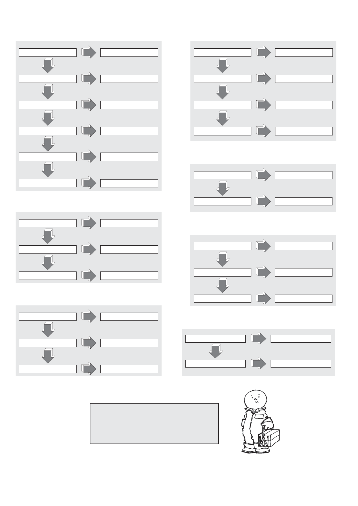
RECHERCHE PANNES
LE MACHINE NE PART PAS (21.2):
BATTERIE DÉCHARGÉE RECHARGER LA BATTERIE
NON
MICRO GOUVERNAIL CASSÉ CHANGER MICRO
NON
FUSIBLE DE PUISSANCE BRÛLÉ CHANGER FUSIBLE
NON
FUSIBLE AUXILIAIRE BRÛLÉ CHANGER FUSIBLE
NON
CLÉ CASSÉE
NON
COURT-CIRCUIT INSTALLATION
ÉLECTRIQUE
OUI
OUI
OUI
OUI
MONTER NOUVELLE CLÉ COMPLÈTE
OUI
OUI
CONTRÔLER INSTALLATION
ÉLECTRIQUE
LES FOURCHES NE RESTENT PAS EN HAUT (26.1):
LES FOURCHES NE SE SOULÈVENT PAS (22.1):
PERTE D’HUILE DANS LE SYSTÈME
HYDRAULIQUE
OUI
NON
SURCHARGE DIMINUER LA CHARGE
OUI
NON
BATTERIE DÉCHARGÉE CHARGER LA BATTERIE
OUI
NON
MANQUE D’HUILE DANS LE RÉSERVOIR
OUI
VÉRIFICATION CONNEXIONS
AJOUTER DE L’HUILE
LES CHARRIOT NE FREINE PAS (23.1):
BAS COUPLE FREINANT ENREGISTRE LE FREIN
NON
P
ANNE DANS LE SYSTÈME FREINANT
OUI
OUI
CHANGER LE FREIN
PERTE D’HUILE DANS LE CIRCUIT
HYDRAULIQUE
OUI
VÉRIFICATION CONNEXIONS ET
NON
V
ALVE DE PRESSION SALE NETTOYER LA VALVE
OUI
NON
JOINTS CYLINDRE USÉS
OUI
CHANGER LES JOINTS
LA MOTOPOMPE NE PART PAS (24.1):
BROSSES MOT. USÉES CHANGER LES BROSSES
NON
SWITCH DE MISE EN MARCHE CASSE
NON
BRANCHEMENTS ÉLECTRIQUES
DÉFECTUEUX
OUI
OUI
OUI
CHANGER LE SWITCH
VÉRIF. BRANCHEMENTS
JOINTS
LA MOTOPOMPE NE PART PAS (24.1):
RECHARGEBATTERIE PAS
BRANCHÉ CORRECTEMENT
NON
FUSIBLE RECHARGE BATTERIES CASSÉ
NON
FUSIBLE CASSÉ LIGNE PRINCIPALE
OUI
OUI
OUI
LA ROUE MOTRICE PATINE (34.2):
HAUTEUR ROUE MOTRICE
ERRONÉE
NON
ROUE MOTRICE USÉE
OUI
OUI
REMPLACER L'ANNEAU DE BANDAGE
VÉRIFICATION CONNEXIONS
CHANGER FUSIBLE
CHANGER FUSIBLE
EFFECTUER LE RÉGLAGE
DE LA ROUE MOTRICE
ATTENTION !!!
SI AUCUNE DES SOLUTIONS CONSEILLEES NE DEVAIT
REPARER LA PANNE, AMENER LE CHARIOT AU SERVICE
D’ASSISTANCE LE PLUS PROCHE.
8
SUMMARY (1.1)
1.1 MANUFACTURER PR INDUSTRIAL PR INDUSTRIAL PR INDUSTRIAL PR INDUSTRIAL PR INDUSTRIAL PR INDUSTRIAL PR INDUSTRIAL
Q kg 1200 1200 1200 1200 1200 1200 1200
c mm 600 600 600 600 600 600 600
x mm 780 780 780 780 780 780 780
y mm 1234 1234 1234 1234 1234 1234 1234
kg 530 545 578 570 585 618 615
kg 543/1187 558/1187 591/1187 583/1187 598/1187 631/1187 628/1187
kg 368/162 383/162 416/162 408/162 423/162 456/162 453/162
b
10
mm 565 565 565 565 565 565 565
b
11
mm 410 410 410 410 410 410 410
h1mm 1787 1987 2250 1787 1987 2250 1965
h
2
mm - - 80 - - 80 1402
h
3
mm 2410 2810 3410 2410 2810 3410 2810
h
4
mm 2992 3392 3916 2992 3392 3916 3372
h
5
mm - - - - - - -
h
14
mm 915/1310 915/1310 915/1310 960/1330 960/1330 960/1330 960/1330
h
13
mm 90 90 90 90 90 90 90
l
1
mm 1760 1760 1760 1760 1760 1760 1760
l
2
mm 609 609 609 609 609 609 609
b
1
mm 800 800 800 800 800 800 800
s/e/l mm 70/150/1150 70/150/1150 70/150/1150 70/150/1150 70/150/1150 70/150/1150 70/150/1150
b
3
mm 650 650 650 650 650 650 650
b
5
mm 560 560 560 560 560 560 560
m
2
mm 20 20 20 20 20 20 20
A
st
mm 2210 2210 2210 2210 2210 2210 2210
W
a
mm 1430 1430 1430 1430 1430 1430 1430
km/h 4,7/5,2 4,7/5,2 4,7/5,2 4,7/5,2 4,7/5,2 4,7/5,2 4,7/5,2
m/s 0,11/0,19 0,11/0,19 0,11/0,19 0,11/0,19 0,11/0,19 0,11/0,19 0,10/0,18
m/s 0,12/0,15 0,12/0,15 0,12/0,15 0,19/0,19 0,19/0,19 0,19/0,19 0,16/0,14
% 5/10 5/10 5/10 5/10 5/10 5/10 5/10
kW 0,7 0,7 0,7 0,7 0,7 0,7 0,7
kW 2,2 2,2 2,2 2,2 2,2 2,2 2,2
V/Ah 24/85 (C20) 24/85 (C20) 24/85 (C20) 24/118 (C5) 24/118 (C5) 24/118 (C5) 24/118 (C5)
kg 38 38 38 78 78 78 78
kWh/h 0,9 0,9 0,9 0,9 0,9 0,9 0,9
dB(A) 62 62 62 62 62 62 62
DESCRIPTION
WEIGHTS
TYRES/CHASSIS
DIMENSIONS
PERFORMANCE
DATA
ELECTRIC
MOTORS
TECHNICAL DATA ...........................................................................pag.9
DECLARATION OF VIBRATION EMISSION ...................................pag.9
USE OF THE MACHINE ..................................................................pag.9
DESCRIPTION OF THE TRUCK .....................................................pag.9
SAFETY DEVICES...........................................................................pag.9/10
PLATES............................................................................................pag.10
TRANSPORT AND SET UP.............................................................pag.10
BATTERY.........................................................................................pag.10
USE ..................................................................................................pag.10/11
MAINTENANCE ..............................................................................pag.11
TROUBLE SHOOTING ....................................................................pag.12
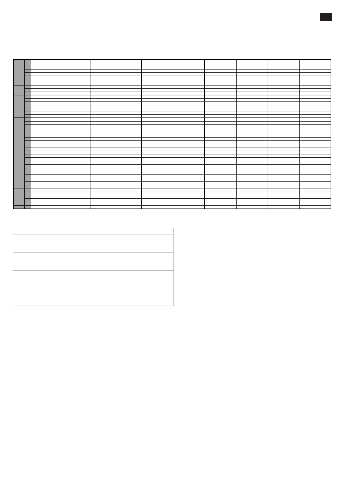
TECHNICAL DATA (3.46)
1.2 MODEL GX 12/25 III ED. BASIC GX 12/29 III ED. BASIC GX 12/35 III ED. BASIC GX 12/25 III ED. EVO GX 12/29 III ED. EVO GX 12/35 III ED. EVO GX 12/29 III ED. FL EVO
1.3 DRIVE ELECTRIC ELECTRIC ELECTRIC ELECTRIC ELECTRIC ELECTRIC ELECTRIC
1.4 OPERATOR TYPE PEDESTRIAN PEDESTRIAN PEDESTRIAN PEDESTRIAN PEDESTRIAN PEDESTRIAN PEDESTRIAN
1.5 LOAD CAPACITY
1.6 LOAD CENTRE DISTANCE
1.8 LOAD DISTANCE, CENTRE OF DRIVE AXLE TO FORK
1.9 WHEEL BASE
2.1 SERVICE WEIGHT
2.2 AXLE LOAD LADED, FRONT/REAR
2.3 AXLE LOAD UNLADEN, FRONT/REAR
3.1 TYRES * G+P/P G+P/P G+P/P G+P/P G+P/P G+P/P G+P/P
3.2 TYRE SIZE, FRONT (Ø x width) 250x76 250x76 250x76 250x76 250x76 250x76 250x76
3.3 TYRE SIZE, REAR (Ø x width) 82x70 82x70 82x70 82x70 82x70 82x70 82x70
3.4 SIDE WHEELS (Ø x width) 100x38 100x38 100x38 100x38 100x38 100x38 100x38
3.5 WHEELS, NUMBER (x=DRIVEN) FRONT/REAR 1x+1/2 1x+1/2 1x+1/2 1x+1/2 1x+1/2 1x+1/2 1x+1/2
3.6 TREAD, FRONT
3.7 TREAD, REAR
4.2 HEIGHT, MAST LOWERED
4.3 FREE LIFT
4.4 LIFT
4.5 HEIGHT, MAST EXTENDED
4.6 INITIAL LIFT
4.9 HEIGHT OF TILLER IN DRIVE POSITION MIN/MAX
4.15 HEIGHT, LOWERED
4.19 OVERALL LENGTH
4.20 LENGHT TO FACE OF FORKS
4.21 OVERALL WIDTH
4.22 FORK DIMENSIONS
4.24 FORK-CARRIAGE WIDTH
4.25 DISTANCE BETWEEN FORK ARMS
4.32 GROUND CLEARANCE, CENTRE OF WHEEL BASE
4.34 AISLE WIDTH FOR PALLETS 800x1200 LENGHTWISE
4.35 TURNING RADIUS
5.1 TRAVEL SPEED, LADEN/UNLADEN
5.2 LIFT SPEED, LADEN/UNLADEN
5.3 LOWERING SPEED, LADEN/UNLADEN
5.8 MAX GRADEABILITY, LADEN/UNLADEN
5.10 SERVICE BRAKE ELECTRIC ELECTRIC ELECTRIC ELECTRIC ELECTRIC ELECTRIC ELECTRIC
6.1 DRIVE MOTOR POWER
6.2 LIFT MOTOR POWER
6.4 BATTERY VOLTAGE, NOMINAL CAPACITY C5
6.5 BATTERY WEIGHT
6.6 ENERGY CONSUMPTION ACC. TO VDI CYCLE
8.4 SOUND LEVEL AT DRIVER'S EAR
*G=Rubber, P=Polyurethane, N=Nylon
EN
DECLARATION OF VIBRATION EMISSION (33.2)
Declared vibration emission values in compliance with EN 12096
Test surfaceDescription Value European Norm (EN)
Measured vibration emission
value, a (m/s
Uncertainty, K (m/s
Measured vibration emission
value, a (m/s
Uncertainty, K (m/s
Measured vibration emission
value, a (m/s2)
Uncertainty, K (m/s
Measured vibration emission
value, a (m/s
Uncertainty, K (m/s
2
)
2
)
2
)
2
)
2
)
2
)
2
)
0.71
0.68
2.3
0.6
0.77
0.39
1.02
0.08
EN ISO 20643
(Hand-Arm)
EN ISO 20643
(Hand-Arm)
EN 13059
(Whole body)
EN 13059
(Whole body)
Industrial smooth
concrete floor
On test track
according to
EN 13059
Industrial smooth
concrete floor
On test track
according to
EN 13059
Values determined in compliance with EN ISO 20643 and EN 13059.
USE OF THE MACHINE (4.1)
This machine has been designed to lift and transport loads on perfectly even floors. An identification plate can be found on the chassis indicating the lifting capacity that must never be exceeded both
for the safety of the personnel and not to damage the vehicle.Please observe the safety, use and maintenance regulations to the letter.Any mounting of extra equipment on the machine must be
authorised by the manufacturers.
DESCRIPTION OF THE TRUCK (5.16) (see fig.1)
This machine is an electric fork lift truck with steering bar drive and is perfect for storing and transporting loads on perfectly even surfaces. The controls are easy to see and use. The machine complies
with all current EEC safety and comfort regulations. The drawing shows its main specifications:
1) STEERING BAR 2) MOTOR WHEEL 3) HYDRAULIC OUTLET 4) FORKS MANUAL RELEASE DEVICE 5) LIFTING FORK 6) SECOND STAGE 7) CHASSIS 8) LIFTING CYLINDER 9) MAIN
SWITCH 10) FORK CONTROL ELECTRONIC BOARD (EVO) 11) ELECTRONIC CARD 12) STABILISING WHEEL 13) COVERS 14) PARACHUTE VALVE 15) BATTERY 16) ELECTRIC BRAKE
17) LOADING ROLLERS 18) HAND GUARD 19) RECTIFIER 20) FORK RAISING CYLINDER (only Free Lift model) 21) SECOND STAGE RAISING CYLINDER (only Free Lift model)
SAFETY DEVICES (6.12) (see fig.1)
1) MASTER SWITCH (ref.9) 2) ELECTRIC BRAKE (ref.16) 3) FLOW LIMITING VALVE (ref.14) 4) MAXIMUM PRESSURE VALVE 5) BUMPERS: they protect the driving wheel (ref. 2), the lateral
stabilizing wheels (ref. 12) and the front loading rollers (ref. 17) from bumps; in case of accidents, therefore, the feet and the load are protected 6) DEAD MAN'S HANDLE (ref.2/fig.3): this is a safety
switch located on the steering bar and protects the driver from collisions when reversing 7) HAND GUARD (ref.18) 8) FORKS MANUAL RELEASE DEVICE (RIF. 4)
Structure (7.10)
The lifting mast, the legs and the hood form a very rigid welded structure (ref. 6). The forks are precision guided by 4 rollers that run up the whole mast. The drive wheel, a pivoted wheel and two rollers
give the truck great stability on 4 points of support. The covers (REF. 13) can be easily opened to allow access to all the units for maintenance.
Drive (8.4)
The drive unit moves the driving wheel by means on conical and cylindrical gears. Movement can be inverted by using the throttle valves located on the steering bar (ref.1/fig.3).
Steering bar (9.12) (rif.1/fig.1)
The truck can be driven by a person. The steering angle is 210°. The steering bar operates directly on the driving wheel, therefore, to change direction turn it in the required direction. To move the truck
(see fig.2) keep the steering bar in its central position (pos.B), while to stop it move it to its upper position (pos.A) or in its lower position (pos.C). When released the steering bar returns automatically
to its upper position (pos.A) and acts as a parking brake. In “tortoise” mode, when the steering wheel is in the upper position (pos. A) or in the lower position (pos. C), if you press the “tortoise” pushbutton
(ref. 8, fig. 3) and act on the start regulator (ref. 1, fig. 3), the carriage will move at a reduced speed.
9

Brakes (10.7)
Service braking is provided by the engine, when releasing the accelerator. The electromagnetic brake acts as a parking brake and emergency brake. Emergency braking is carried out by moving the
tiller to the upper position (pos.A) or to the lower position (pos.C) (see fig.2). If the electrical system is off, the electromagnetic brake acts as a parking brake.
Hydraulic circuit (11.11)
To raise and lower the forks, use the steering bar control buttons (ref.4,5/fig.3) so that the motor pump (ref.3/fig.1) sends the hydraulic oil from the tank to the lifting cylinder. The energy necessary for
effective work is supplied by the battery (ref.15/fig.1).
In the event of an electric failure or battery discharging when the forks are lifted, it is possible to lower them to move the truck away acting on the manual release device (RIF.4/FIG.1) on the power
pack.
Two safety valves are installed in the hydraulic circuit:
a) Hose burst valve stops the load from falling suddenly in case the hydraulic system fails and is contained in the lift cylinder
b) Maximum pressure valve, this is contained in the motor pump and protects the mechanical and hydraulic system from overloading.
Electrical circuit (12.9)
Constructed according to current regulations and comprising a programmable electronic variator (ref.11/fig.1) (supplied with all safety and adjustment devices)
and controls that can be operated from the steering bar handle. The connections are guaranteed against accidental loosening. The copper conductors are very
flexible and have a diameter sufficient for operating conditions and any external events that could occur. All the electrical components are mounted so as to
guarantee operation and facilitate maintenance.
PLATES (13.13)(see fig.4)
The following plates are visible on the machine:
A) Plate that identifies the kind of vehicle B) Battery plate C) Plate showing the loading diagram according to the lifting height and the position of the center of
gravity of the load on the forks D) Plates indicating the harness points E) Plates indicating that feet may be squashed F) Plate forbidding use G) Plate: read the
instructions H) Plate indicating the height to which forks are approximately raised I) “Tortoise” Pushbutton Tag Attention: In no case may the plates be removed
or made illegible.
IMPORTANT: IT IS FORBIDDEN TO EXCEED THE LOAD SHOWN ON THE C TYPE PLATE FIXED TO THE MACHINE AT THE MOMENT OF SALE AND SHOWN HEREUNDER:
This diagram illustrates the relationship between the maximum load that can be lifted and the relative maximum heights from the ground during loading and unloading operations of a
pallet from a shelf.
The fork diagram shown to the side indicates the center of gravity of the load that, however, must be distributed as uniformly as possible along the whole length of the fork!!
TRANSPORT AND SET UP
Transport (14.10)
To transport the truck two harness points are supplied, indicated by the "D" type plates (fig.4), while the weight of the truck is indicated on the "A" type identification plate (fig.4).
Before to sling the truck is recommended to remove the upper hands protection (Ref. 18, fig. 1) in order to avoid its damage. Mount the protection again before to start working with the truck.
While driving, make sure the truck is firmly fixed, to avoid its tilting. Make sure that no acid nor vapor is leaking from the battery (if any).
Set up (15.1)
Before starting the machine check that all the parts are in perfect condition, check the performance of all the units and the safety devices. Move the truck with battery current and never with rectified
alternating current so as not to damage the electrical components.
BATTERY (16.7)
Instructions, safety measures and maintenance
Inspection, charging and substitution of the battery must be carried out by authorized personnel following the manufacturer's instructions. It is forbidden to smoke or keep inflammable or spark-producing
material near the truck or the battery recharger. The area must be kept well aired. The caps of the elements must be kept dry and clean. Remove any acid that has leaked out and spread a little Vaseline
on the terminals and then tighten them. The weight and size of the batteries can effect the stability of the truck, therefore, if a non-standard battery is mounted it is advisable to contact the MANUFACTURERS
for the relative authorization.
The truck is fitted with a battery status indicator that lights when the truck is turned on. In case of inactivity of the truck, the indicator automatically turns off, lighting again with a new usage. The green
LED light indicates that battery charge is sufficient. When the charge is no longer sufficient the light turns yellow, indicating that charge is available only for some further lifting cycles. When the residual
charge is lower than 20%, red LED light turns on. At this stage is no longer possible to lift the forks, but the truck can only move to the nearest charging point. The battery status indicator turns on during
the charging phase, indicating its progress.
Charging the battery
Before charging check the performance of the conductors. Connect the battery charger plug (A) to the grid (check fig.3). Once the batteries are charged, the battery charger stops with the current
supply and the green led of the battery level indicator switches on. Remove the battery charger plug (A) from the grid. A normal battery charge lasts about 10-12 hours. It is better to charge batteries
at the end of the working time of the truck. The battery charger has been designed to maintain charging for a certain period of time after completing charging. There is no risk of overloading and therefore
it is unnecessary to remove the battery charger after completing recharging.
Never completely discharge the battery and avoid partial charging; Allow the battery charger to signal completion of charging. WARNING: If the batteries are allowed to run down too
much their life will be shortened.
Substituting the battery (17.4)
a) Remove the rear cover; b) Remove the cables from the battery terminals; c) Slide out the battery; d) Following the reverse order reassemble the battery, secure it to its seat and connect it
correctly.
(the battery must always be of the same type that it replaces) IMPORTANT: USE THE SULPHURIC ACID WITH CARE, IT IS TOXIC AND CORROSIVE; IF SKIN OR CLOTHES COME INTO CONTACT
WITH THIS
ACID WASH WITH ABUNDANT SOAP AND WATER. IN CASE OF ACCIDENTS CONSULT A DOCTOR!!! After replacing the battery, consign the used one to the nearest collecting center.
Battery check
Carefully read the battery manufacturer’s use and maintenance instructions. Check that there is no corrosion, that Vaseline is present on the poles and that the acid is 15 mm above the plates. If the
elements are not covered, top up with distilled water. Measure electrolyte density with a densimeter to check the charging level.
USE (18.17)
The driver must carry out the following instructions of use in the driving position in way to remain reasonably distant from the dangerous zones (such as masts, forks, chains, pulleys, driving and
stabilizing wheels and any other movable part), that can cause the crushing of hands and/or foots.
Safety Regulations
The truck must be used according to the following regulations:
The driver of the machine must be properly trained, must know the instructions for use of the vehicle and wear appropriate clothing and a helmet.
The driver responsible for the fork lift truck must not allow unauthorized personnel to drive the truck or to step onto the forks or the platform.
While the truck is in movement the operator must reduce speed in curves, in narrow corridors, through doors or on irregular surfaces. He must keep unauthorized personnel away from the area where
the truck is working and immediately warn people if they are in danger; if, in spite of this warning there is still someone in the work area the driver must immediately stop the truck.
It is forbidden to stop in areas where there are moving parts and step on the fixed parts of the truck.
The driver must avoid sudden stops and fast inversions of movement.
In case of slopes with maximum permitted inclination, the driver must keep the load above the truck and reduce speed.
When driving the driver must make sure that visibility is good and that there are no obstructions when reversing.
If the truck is transported in lifts he must enter them with the loading forks in front (first make sure the lift has a sufficient load)
It is absolutely forbidden to disconnect or dismount the safety devices. If the truck is used in areas with a high risk of fire or explosion, it must be approved for this kind of use.
The loading capacity of the truck must in no case be exceeded. The driver must ensure that the load is well placed on the forks and in perfect order; the load must not jut out more than 50mm from the
end of the forks.
It is forbidden to move the truck with the forks in their upper position. This is allowed only when maneuvering to put down and pick up loads
Before beginning work the driver of the truck must check:
- the performance of the service and parking brake
- that the loading forks are in perfect order
- that the wheels and the rollers are not damaged
- that the battery is charged, well fixed and the elements perfectly dry and clean
- that all the safety devices are in working order
Once the battery (ref. 7/fig. 3) signals that it only has 20% charge left, the trolley/truck must stop being used and, therefore, recharged.
The truck must always be used or parked sheltered from rain and snow and in no case must it be used in very damp areas.
Temperature of use -10°, +40°.
Do not use the truck to tow trailers or other trucks
Immediately report damages, failures on malfunctions to the responsible personnel. Do not use the truck until it is repaired
Drivers without the required license cannot repair the truck, furthermore they are not authorized to deactivate or modify the safety devices and switches.
THE MANUFACTURERS SHALL NOT BE HELD LIABLE IN CASE OF FAULTS OR ACCIDENTS DUE TO NEGLIGENCE, INCAPACITY, AND INSTALLATION BY UNQUALIFIED TECHNICIANS
AND IMPROPER USE OF THE TRUCK.
10
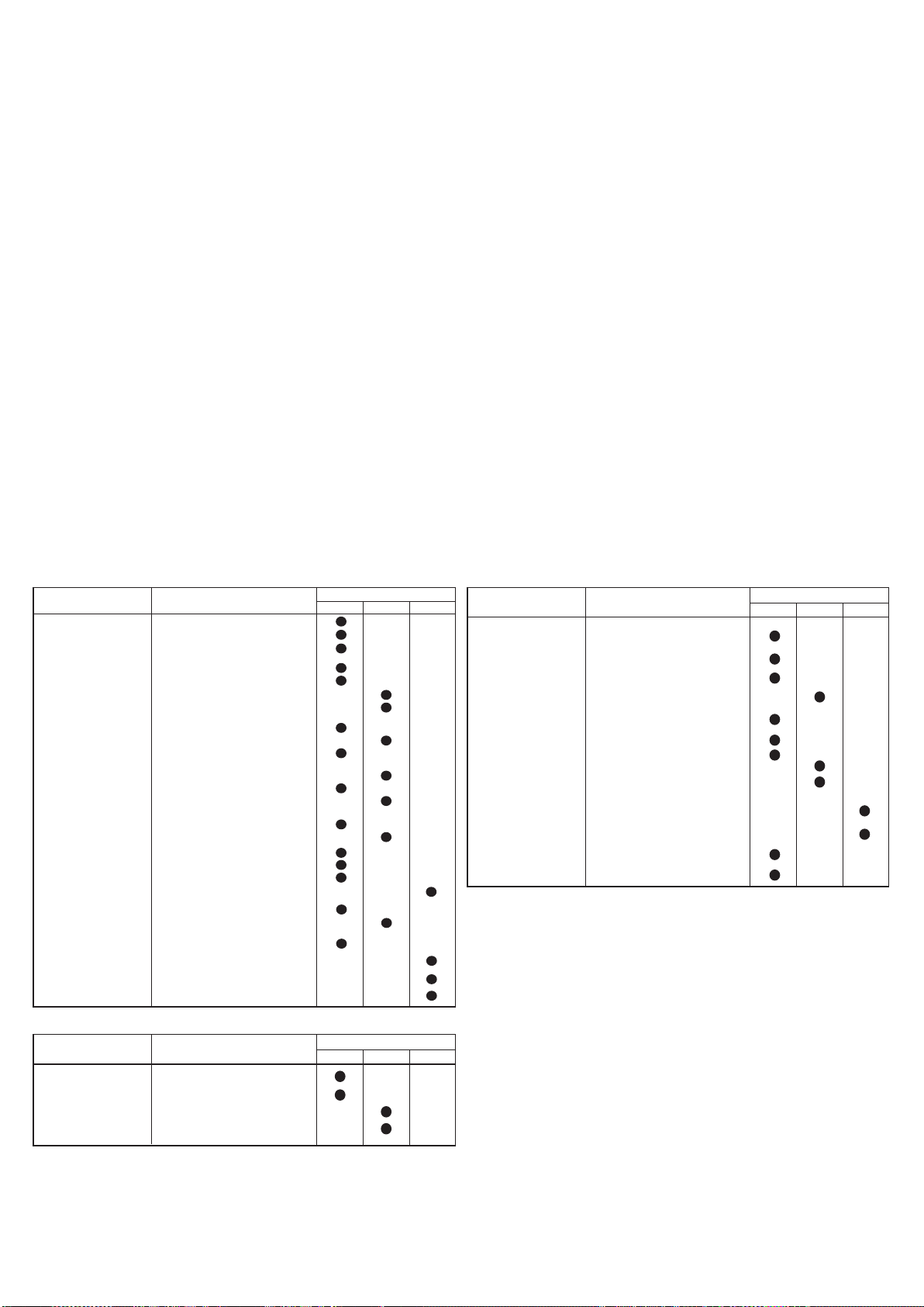
Movement (see fig.6)
Before moving the truck check that the horn and the brake work and that the battery is completely charged. Turn the key to the 1 position and move the steering bar to its movement position. Turn the
governor slowly and move towards the relative work area. To brake or stop turn the governor in the opposite direction. Always steer the truck slowly as sudden movements can provoke dangerous
situations (particularly when the truck moves at high speeds). Always drive with the load in a low position, reduce speed in narrow corridors and on curves.
Stacking
Approach the shelving carefully with the load low.
make sure that the legs of the truck are free to move under the pallet or in the shelving. The best way to do this is to put the side of the pallet to be lifted in a perfect line with the top pallet in the shelving
using it as reference. In this way loading and unloading will be easier.
Lift the load until it rises above the level of the shelf.
Move slowly forwards and stop when the load is above the shelf; at this point lower the forks so as to free them from the pallet and not exert force on the underlying shelf. Make sure that the load is
safely positioned.
Move slowly backwards making sure the pallet remains firmly positioned.
Lower the forks to their position of movement (FIG. 6)
Unloading
1) With the forks lowered and perpendicular approach the shelving and enter under the bottom pallet 2) Return with the forks out of the pallet 3) Raise the forks to the required height and slowly move
towards the pallet to be unloaded. At the same time make sure that the forks enter under the pallet easily and that the load is safely positioned on the forks. 4) Raise the forks until the pallet is lifted
from the level of the shelf 5) Move slowly backwards in the corridor 6) Lower the load slowly at the same time making sure that the forks do not touch obstacles while lowering
Mode of use with reduced speed (“Creep speed”)
To use the truck in narrow spaces or to handle with precision delicate goods, it is possible to use the truck in “creep speed mode”. Creep speed mode is available only with the tiller bar completely
raised. To use the truck with creep speed mode, keep pressed the dedicated button on the rear part of tiller head (ref. 8/fig. 3) on which is impressed a pictogram of a tortoise and operate on translation
and forks moving controls as in standard mode.
WARNING: Always check the weight of the load with the lifting capacity relative to the height indicated on the appropriate plate.
WARNING: When the load is lifted steering and braking maneuvers must be carried out slowly and very carefully.
Lift locking device (28.2)
The lift truck is provided with an automatic device which stops the lifting if the batteries reach a discharge rate over 80%. The action of this device is shown by the red led on the battery level indicator.
If this device intervenes, it is necessary to drive the truck to a battery charger and act as described in the section “Battery charging”.
Controls (19.13) - (see fig.3)
1. Accelerator; 2. Dead man’s handle; 3. Audible detector pushbutton; 4. Raising button; 5. Lowering button; 6. Master switch; 7. Battery warning light; 8. Creep speed button (reduced speed)
9. Battery status and hour-counting display
MAINTENANCE (20.14)
Maintenance must be carried out by specialized personnel. The truck must undergo a general check up at least once a year. After every maintenance operation the performance of the truck and its
safety devices must be checked. Inspect the truck periodically so as not to risk the machine stopping or danger for personnel! (see maintenance table).
Maintenance table
ELEMENT CHECKS
STRUCTURE
AND FORKS
BRAKES
WHEELS
STEERING BAR
ELECTRICAL SYSTEM
HYDRAULIC SYSTEM
Check load bearing elements
Check nuts and bolts are tightened
Check for backstops and play
Check performance
Check lining for wear
Check braking power
Check play (about 0,4 mm)
Check wear
Check bearing play
Check anchorage
Check playu
Check sideways movement
Check return to vertical position
Check wear of remote control switch
Check connections, cable trouble
Check master switch
Check horn
Check dead man's button
Check fuse values
Check performance
Check oil level
Check for leaks and wear
of connections
Change oil/filter
Check performance of pressure
limiting valve
Check flow limiting valve
Lubrication table
LUBRICATION
POINTS
WHEELS AND ROLLERS
LIFTING CHAIR
MAST GUIDES
HYDRAULIC UNIT
Lithium grease NLGI-2
Lithium grease NLGI-2
Lithium grease NLGI-2
ISO VG 32
Oil
KIND OF
LUBRICATOR
3 Months 6 Months 12 Months
EVERY
EVERY
3 Months 6 Months 12 Months
ELEMENT CHECKS
CYLINDER
Check performance leaks and
wear of gaskets
EVERY
3 Months 6 Months 12 Months
Check pulleys
ELECTRIC MOTORS
Check wear of brushes
Check starting motor relay
BATTERY
Check electrolyte density and level
(not necessary for gel batteries)
Check voltage of elements
Check anchorage and hold of terminals
Check cables
Grease terminals with Vaseline
INSPECTIONS
Check connection to electrical
circuit earth
Check ascent and descent
speed of lifting forks
Check safety devices
Test raising and lowering with
nominal load
Setting the drive wheel height (Fig. 5)
Set the drive wheel height following the next steps:
1) Unmount the lower cover;
2) Keeping the tiller in “0” position, insert a screwdriver in the spacer hole rif.1,
then turn the tiller towards “A” direction (1/4 turn = 0,5 mm extraction of the
drive wheel);
3) Remove the screwdriver and rotate the tiller towards “B” direction, returning
in “0” position;
4) Ripeat steps 2 and 3 until it is needed (In case the wheel results excessively
extracted repeat the 2 and 3 steps turning the tiller towards the opposite
direction);
5) Lock the ferrule ref.2 against the spacer ref.1, then replace the lower cover.
Note: replace the wheel before its thickness is lower than 5 mm.
Use hydraulic oil apart from motor and brake oil.
Note: respect the environment when discarging the used oil. The oil should be stored
in adrum that should be consigned to the nearest collecting station. Do not dump the
oil in the ground or in unsuitable places.
CLEANING THE TRUCK: Clean the parts of the truck, except electrical and electronic
elements, with a damp cloth. Do not use direct jets of water, steam or inflammable liquids.
Clean electrical and electronic components with dehumidified compressed air at low pressure
(max. 5 bar) or with a non metallic brush.
11
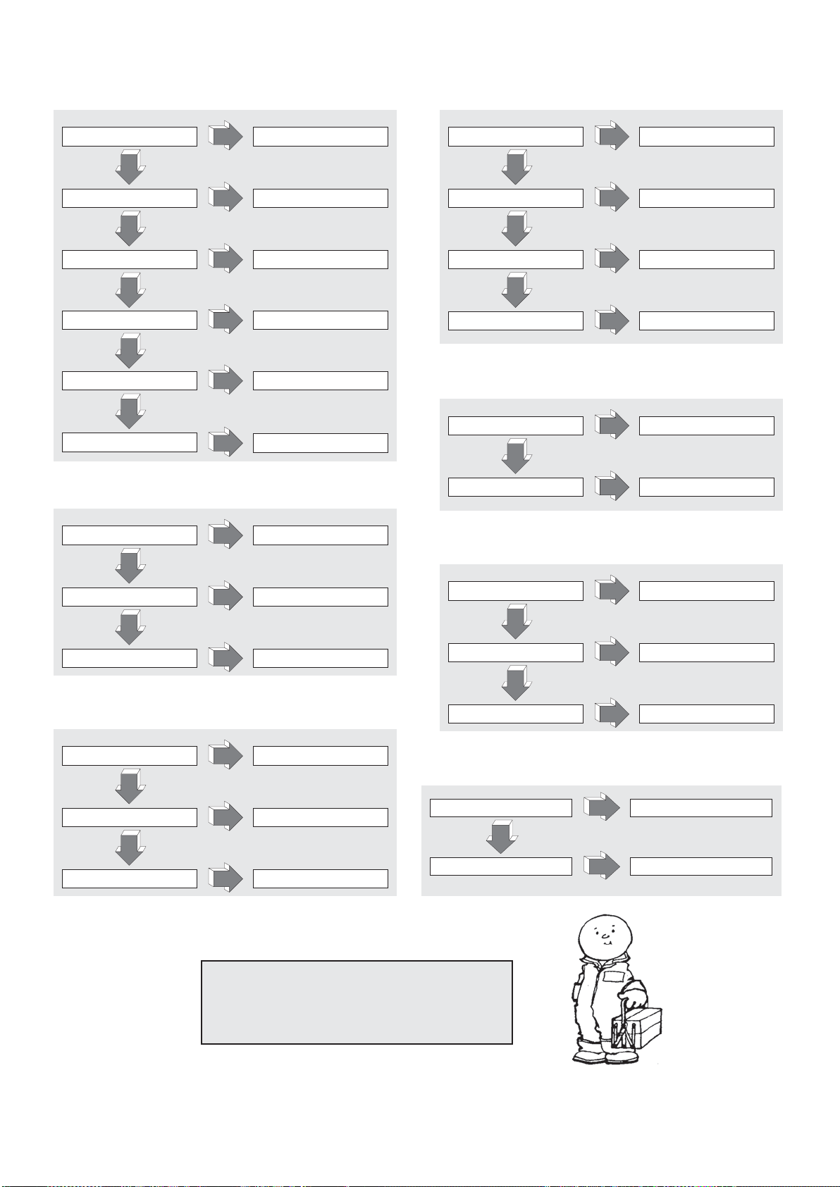
TROUBLE SHOOTING
THE MACHIN DOESN’T START (21.2):
BATTERY FLAT CHARGE BATTERY
NO
DRAWBAR MICRO SWITCH
BROKEN
NO
POWER FUSE BLOWN REPLACE
NO
SECONDARY FUSE BLOWN REPLACE
NO
KEY BROKEN MOUNT NEW COMPLETE KEY
NO
SHORT CIRCUIT IN ELECTRICAL
SYSTEM
YES
YES
YES
YES
YES
YES
REPLACE
CHECK ELECTRICAL SYSTEM
THE FORKS GASKETS DON’T STAY RAISED (26.1):
THE GASKETS DON’T RISE (22.1):
OIL LEAKAGE IN
HYDRAULIC CIRCUIT
NO
OVERLOADING REDUCE LOAD
NO
BATTERY FLAT CHARGE BATTERY
NO
NO OIL IN TANK ADD OIL
YES
YES
YES
YES
CHECK CONNECTIONS AND
THE TRUCK DOESN'T BRAKE (23.1):
LOW BRAKING TORQUE ADJUST BRAKE
NO
F
AULT IN BRAKING SYSTEM REPLACE BRAKE
YES
YES
GASKETS
OIL LEAKAGE IN
HYDRAULIC CIRCUIT
NO
PRESSURE VALVE DIRTY CLEAN VALVE
NO
CYLINDER GASKETS WORN
YES
YES
YES
THE MOTOR PUMP DOESN ’
MOTOR BRUSHES WORN REPLACE
NO
STARTING SWITCH BROKEN REPLACE
NO
ELECTRICAL CONNECTIONS
FAULTY
YES
YES
YES
CHECK CONNECTIONS
T START (24.1):
CHECK CONNECTIONS
AND GASKETS
REPLACE GASKETS
THE BATTERY DOESN'T CHARGE (25.1):
BATTERY CHARGER NOT
CONNECTED CORRECTLY
NO
BATTERY CHARGER FUSE BLOWN
NO
MAINS SUPPLY FUSE BLOWN
YES
YES
YES
THE DRIVE WHEEL SLIPS (34.2):
DRIVE WHEEL HEIGHT
NOT CORRECT
NO
DRIVE WHEEL WORN
YES
YES
CARRY OUT ADJUSTMENT
REPLACE DRIVE WHEEL RING
CHECK CONNECTIONS
REPLACE
REPLACE
A
TTENTION !!!
IF NONE OF THE SOLUTIONS SUGGESTED SOLVES
THE PROBLEM, TAKE THE ELEVATOR TO THE
NEAREST SERVICE CENTER.
12
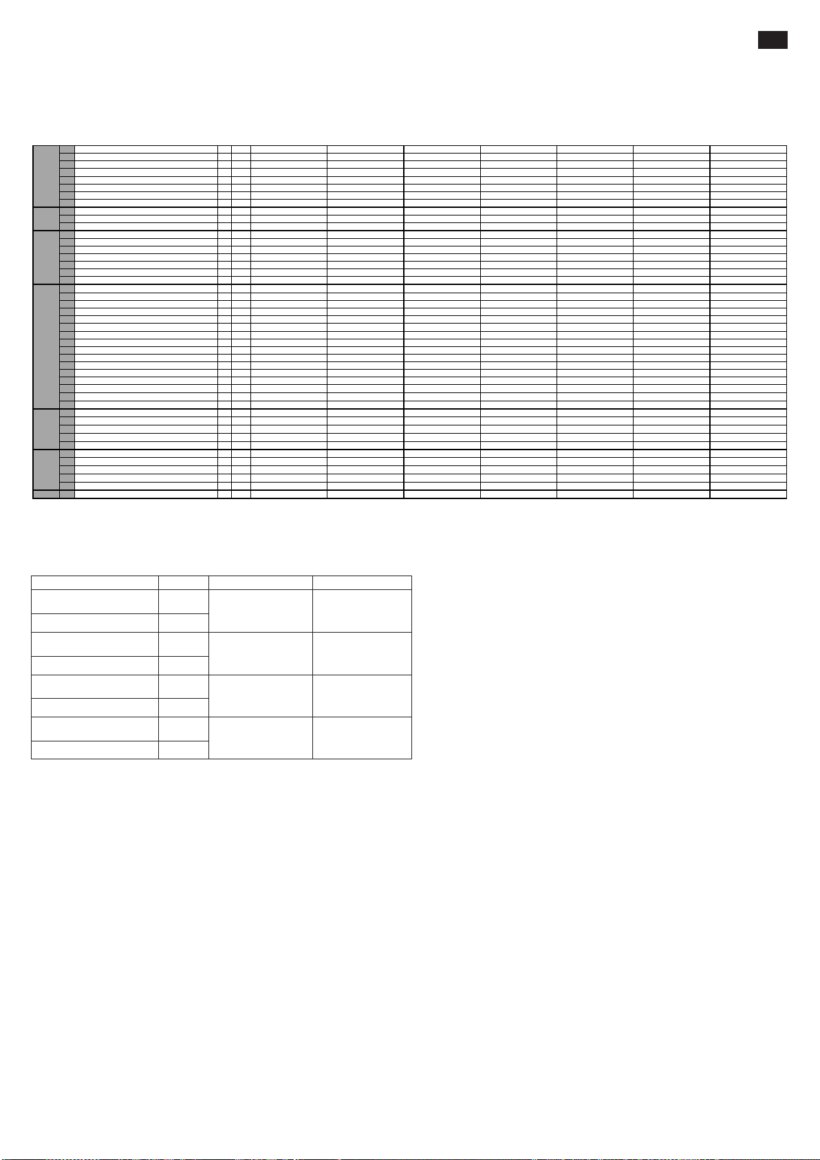
INHALTSVERZEICHNIS (1.1)
TECHNISCHE DATEN..................................................................... s.13
ERKLÄRUNG VON SCHWINGUNGSEMISSION............................ s.13
GEBRAUCH DES GERÄTES ..........................................................s.13
BESCHREIBUNG DES HUBWAGENS............................................ s.13
SICHERHEITSANLEITUNGEN........................................................ s.13/14
SCHILDER .......................................................................................s.14
TRANSPORT UND INBETRIEBNAHME..........................................s.14
BATTERIE........................................................................................s.14
GEBRAUCH ..................................................................................... s.14/15
WARTUNG....................................................................................... s.15
BESTIMMUNG DER SCHÄDEN...................................................... s.16
TECHNISCHE DATEN (3.46)
1.1 HERSTELLER PR INDUSTRIAL PR INDUSTRIAL PR INDUSTRIAL PR INDUSTRIAL PR INDUSTRIAL PR INDUSTRIAL PR INDUSTRIAL
1.2 TYPZEICHEN DES HERSTELLERS GX 12/25 III ED. BASIC GX 12/29 III ED. BASIC GX 12/35 III ED. BASIC GX 12/25 III ED. EVO GX 12/29 III ED. EVO GX 12/35 III ED. EVO GX 12/29 III ED. FL EVO
1.3 ANTRIEB ELEKTRO ELEKTRO ELEKTRO ELEKTRO ELEKTRO ELEKTRO ELEKTRO
1.4 BEDIENUNG GEH GEH GEH GEH GEH GEH GEH
1.5 TRAGFÄHIGKEIT
1.6 LASTSCHWERPUNKT c mm 600 600 600 600 600 600 600
KENNZEICHEN
1.8 LAS
1.9 RADSTAND y
2.1 EIGENGEWICHT kg 530 545 578 570 585 618 615
2.2 ACHSLAST MIT
2.3 ACHSLAST OHNE LAST
GEWICHT
3.1 BEREIFUNG * G+P/P G+P/P G+P/P G+P/P G+P/P G+P/P G+P/P
3.2 REIFENGRÖßE, VORN (Ø x Breite) 250x76 250x76 250x76 250x76 250x76 250x76 250x76
3.3 REIFENGRÖßE, HINTEN (Ø x Breite) 82x70 82x70 82x70 82x70 82x70 82x70 82x70
3.4 ZUSATZRÄDER (Ø x Breite) 100x38 100x38 100x38 100x38 100x38 100x38 100x38
K
3.5 RÄDER,
3.6 SPURWEITE, VORN
RÄDER/FAHRWER
3.7 SPURWEITE, HINTEN
4.2 HÖHE HUBGERÜST EINGEF
4.3 FREIHUB
4.4 HUB
4.5 HÖHE HUBGERÜST
4.6 INITIALHUB
4.9 HÖHE DEICHSEL IN F
4.15 HÖHE GESENKT
4.19 GESAMTLÄNGE
4.20 LÄNGE EINSCHL. GABELRÜCKEN
4.21 GESAMTBREITE
4.22 GABELZINKENMAßE s/e/l mm 70/150/1150 70/150/1
4.24 GABELTRÄGERBREITE
GRUNDABMESSUNGENE-MOTOR
4.25 GABELAUßENABSTAND
4.32 BODENFREIHEIT MITTE RADST
4.34 ARBEITSGANGBREITE BEI PALETTE 800x1200 LÄNGS
4.35 WENDERADIUS
5.1 FAHRGESCHWINDIGKEIT MIT
5.2 HUBGESCHWINDIGKEIT MIT
5.3 SENKGESCHWINDIGKEIT MIT
5.8 MAX STEIGFÄHIGKEIT MIT
5.10 BETRIEBSBREMSE ELEKTRO ELEKTRO ELEKTRO ELEKTRO ELEKTRO ELEKTRO ELEKTRO
LEISTUNGSDATEN
6.1 FAHRMOTOR, LEISTUNG kW 0,7 0,7 0,7 0,7 0,7 0,7 0,7
6.2 HUBMOTOR, LEISTUNG kW 2,2 2,2 2,2 2,2 2,2 2,2 2,2
6.4 BA
6.5 BATTERIEWICHT kg 38 38 38 78 78 78 78
6.6 ENERGIEVERBRAUCH NACH VDI-ZYKLUS kWh/h 0,9 0,9 0,9 0,9 0,9 0,9 0,9
8.4 SCHALLDRUCKPEGEL, FAHREROHR dB(A) 62 62 62 62 62 62 62
* G=Gummi, P=Polyurethan, N=Nylon
/ LAST Q kg 1200 1200 1200 1200 1200 1200 1200
TABSTAND x mm 780 780 780 780 780 780 780
LAST VORN/HINTEN kg 543/1187 558/1187 591/1187 583/1187 598/1187 631/1187 628/1187
VORN/HINTEN kg 368/162 383/162 416/162 408/162 423/162 456/162 453/162
ANZAHL VORN/HINTEN (x=ANGETRIEBEN) 1x+1/2 1x+1/2 1x+1/2 1x+1/2 1x+1/2 1x+1/2 1x+1/2
AHREN h1mm 1787 1987 2250 1787 1987 2250 1965
AUSGEFAHREN
AHRSTELLUNG MIN/MAX
AND
/ OHNE LAST km/h 4,7/5,2 4,7/5,2 4,7/5,2 4,7/5,2 4,7/5,2 4,7/5,2 4,7/5,2
/ OHNE LAST m/s 0,11/0,19 0,11/0,19 0,11/0,19 0,11/0,19 0,11/0,19 0,11/0,19 0,10/0,18
/ OHNE LAST m/s 0,12/0,15 0,12/0,15 0,12/0,15 0,19/0,19 0,19/0,19 0,19/0,19 0,16/0,14
/ OHNE LAST % 5/10 5/10 5/10 5/10 5/10 5/10 5/10
TTERIESPANNUNG, NENNKAPAZITÄT C5 V/Ah 24/85 (C20) 24/85 (C20) 24/85 (C20) 24/118 (C5) 24/1
mm 1234 1234 1234 1234 1234 1234 1234
mm 565 565 565 565 565 565 565
b
10
mm 410 410 410 410 410 410 410
b
11
mm - - 80 - - 80 1402
h
2
mm 2410 2810 3410 2410 2810 3410 2810
h
3
mm 2992 3392 3916 2992 3392 3916 3372
h
4
mm - - - - - - -
h
5
mm 915/1310 915/1310 915/1310 960/1330 960/1330 960/1330 960/1330
h
14
mm 90 90 90 90 90 90 90
h
13
mm 1760 1760 1760 1760 1760 1760 1760
l
1
mm 609 609 609 609 609 609 609
l
2
mm 800 800 800 800 800 800 800
b
1
mm 650 650 650 650 650 650 650
b
3
mm 560 560 560 560 560 560 560
b
5
mm 20 20 20 20 20 20 20
m
2
mm 2210 2210 2210 2210 2210 2210 2210
A
st
mm 1430 1430 1430 1430 1430 1430 1430
W
a
150 70/150/1150 70/150/1150 70/150/1150 70/150/1150 70/150/1150
18 (C5) 24/118 (C5) 24/118 (C5)
DE
ERKLÄRUNG VON SCHWINGUNGSEMISSION (33.2)
Schwingungsemissionswerte gemäß der Normen EN 12096
Gemessener
Schwingungsemissionswert, a (m/s
Unklar, K (m/s
Gemessener
Schwingungsemissionswert, a (m/s
Unklar, K (m/s
Gemessener
Schwingungsemissionswert, a (m/s
Unklar, K (m/s
Gemessener
Schwingungsemissionswert, a (m/s
Unklar, K (m/s
2
)
2
)
2
)
2
)
0.71
2
)
0.68
2.3
2
)
0.6
0.77
2
)
0.39
1.02
2
)
0.08
Europäische Norm (EN)
EN ISO 20643
(Hand-Arm)
EN ISO 20643
(Hand-Arm)
EN 13059
(Ganzer körper)
EN 13059
(Ganzer körper)
TestoberflächeBeschreibung Wert
Fußboden aus
industriell glattem
Zement
Auf Testfläche gemäß
der Normen EN 13059
Fußboden aus
industriell glattem
Zement
Auf Testfläche gemäß
der Normen EN 13059
Werte in Übereinstimmung gemäß der Normen EN ISO 20643 und EN 13059.
GEBRAUCH DES GERÄTES (4.1)
Dieses Gerät wurde für den Transport und zum Heben von Lasten auf einem vollkommen glatten Untergrund ohne Unebenheiten entwickelt. Auf dem Gehäuse befindet sich ein Typenschild mit der
Hubleistung, die zur Sicherheit des Personals und um eine Beschädigung des Hubwagens zu vermeiden, auf keinen Fall überschritten werden darf. Es wird empfohlen, die Anmerkungen zur Unfallverhütung,
zum Betrieb und zur Wartung des Gerätes streng zu befolgen. Das Anbringen von irgendwelchen zusätzlichen Ausrüstungsgegenständen an dem Gerät muß vom Hersteller vorher genehmigt werden.
BESCHREIBUNG DES HUBWAGENS (5.16)
Dieser Wagen ist ein elektrischer Hubwagen mit Gabeln, die über die Deichsel gesteuert werden, geeignet zur Lagerung und zum Transport von Lasten auf ebenen Flächen, die frei von Unebenheiten sind. Die
Steuerorgane sind gut sichtbar und lassen sich leicht bedienen. Der Hubwagen entspricht den derzeitigen Komfort- und Sicherheitsvorschriften der EG.
Die Zeichnung zeigt die wichtigsten Teile:
1) UERDEICHSEL 2) RIEBSRAD 3) RAULISCHE STEUEREINHEIT 4) GABELN HANDENTSPERRUNG 5) GABELN 6) ZWEITE STUFE 7) RGESTELL 8) ZYLINDER 9) HAUPTSCHALTER
10) HAUPTELEKTRONIK GABELSTEUERUNG (EVO) 11) WECHSELRICHTER 12) STUTZRAD 13) GEHAUSE 14) UBERLASTVENTILE 15) BATTERIE 16) ELEKTROBREMSE 17) LASTROLLEN
18) HANDSCHUTZ 19) GLEICHRICHTER 20) GABELHEBEZYLINDER (nur für die Version Free Lift) 21) HEBEZYLINDER ZWEITES STADIUM (nur für die Version Free Lift)
SICHERHEITSANLEITUNGEN (6.12) (s. abb.1)
1) HAUPTSCHALTER (Teil 9) 2) ELEKTROBREMSE (Teil 16) 3) VENTIL ZUR FLUSSREDUZIERUNG (Teil 14) 4) ÜBERDRUCKVENTIL 5) SCHUTZVORRICHTUNGEN STOSSFÄNGER: schützen das
Antriebsrad (Teil 2), die seitlichen Stützräder (Teil 12) und die vorderen Lastrollen (Teil 17) vor Stößen; so werden die Füße und Last im Fall von Stößen geschützt. 6) TASTVORRICHTUNG "TOTER MANN"
(Teil 2/Abb.3): hierbei handelt es sich um einen Sicherheitsschalter auf der Steuerdeichsel, der den Fahrer vor dem Aufprall beim Rückwärtsfahren schützt. 7) HANDSCHUTZ (Teil 18). 8) GABELN
HANDENTSPERRUNG (Teil 4)
Aufbau (7.10)
Der Aufbau, bestehend aus Hubgerüst, Beinen und Motorhaube, ist geschweißt und vollkommen unbiegsam (Teil 7). Die Gabeln werden mit äußerster Genauigkeit von 4 Rollen geleitet, die über die
Gesamthöhe des Hubgerüstes laufen. Das Antriebsrad, ein sich drehende Räder und zwei Rollen verleihen dem Hubwagen auf 4 Stützpunkten große Stabilität. Die Gehäuse (Teil 13) sind einfach zu öffnen
und der Kundendienst kommt leicht an alle Einheiten.
Antrieb (8.4)
Die Antriebseinheit treibt das Antriebsrad über kegel- und zylinderförmige Zahnräder an. Die Fahrtrichtung kann durch Betätigung der Flügel auf der Steuerdeichsel (teil 1/Abb.3) umgekehrt werden.
Deichsel (9.12) (teil 1, abb.1)
Der Hubwagen kann von einem stehenden Fahrer bedient werden. Der Einschlagwinkel beträgt 210°. Der Deichsel steuert direkt das Antriebsrad, so ist er für eine Fahrtrichtungsänderung in die gewünschte
Richtung zu drehen. Um den Hubwagen zu betätigen (siehe Abb. 2), wird der Deichsel in der zentralen Position (pos.B) gehalten. Um ihn zu stoppen, wird er hingegen in die obere (pos.A) oder untere
(pos.C) Position gebracht. Wenn der Deichsel losgelassen wird, kehrt er automatisch in die obere Position (pos.A) zurück und dient als Parkbremse. In “Schildkröten”- Modus gilt, dass, wenn sich das
Steuer in oberer Position (Position A ) oder in unterer Position befindet (Position C) und wenn man durch Drücken die akustische Taste “Schildkröte” betätigt (Siehe 8, Figur 3) und den Betriebsregler aktiviert
(Siehe 1, Figur 3), sich der Wagen bei verringerter Geschwindigkeit fortbewegt.
(s. abb.1)
13
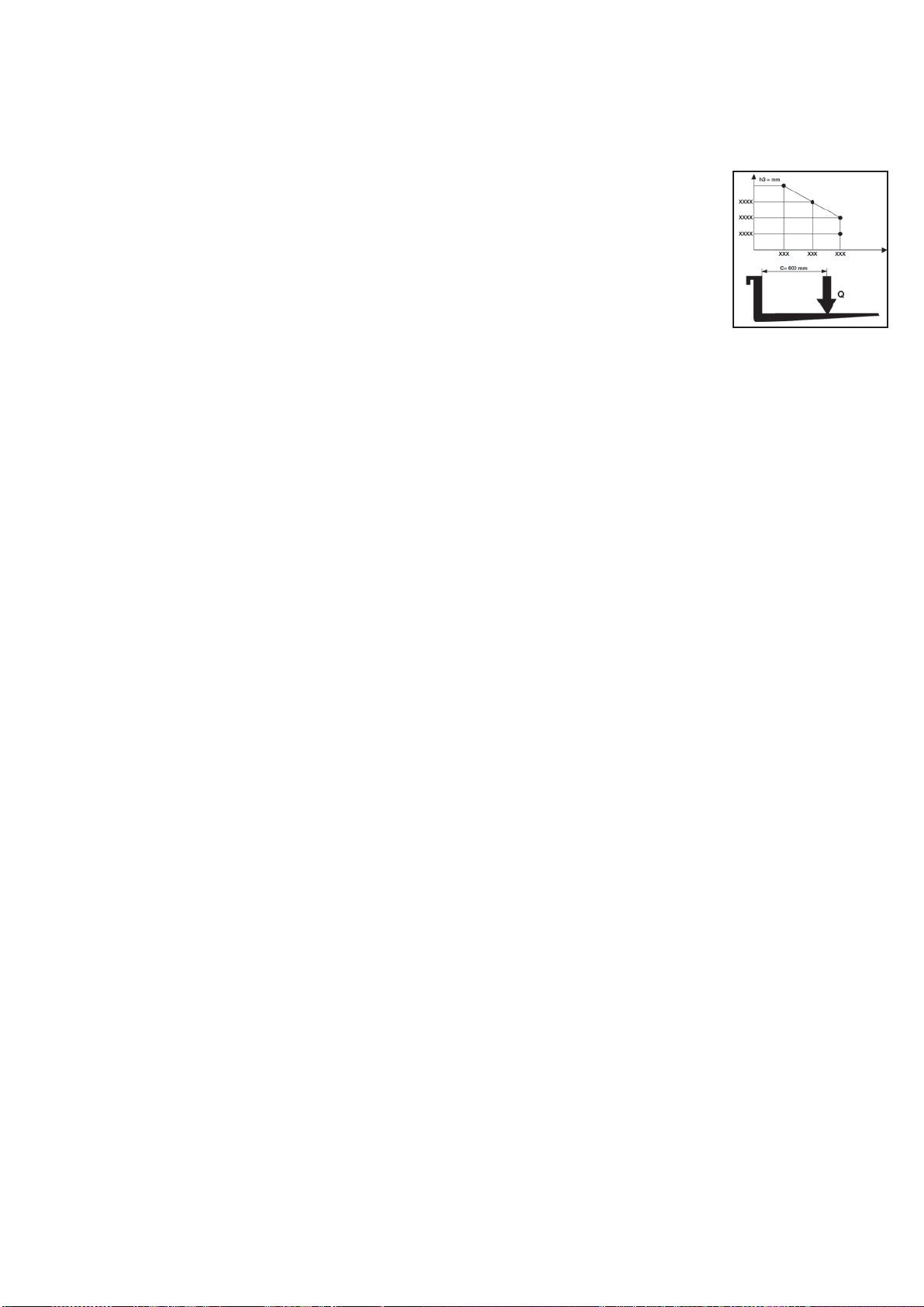
Bremsen (10.7)
Die elektromagnetische Bremse wirkt entweder über, oder durch Einstellen der Deichsel in die höhere Stellung (Stellung A) und in die untere Stellung (Stellung C), s. Abb. 2, direkt auf den Antriebsmotor
ein. Beim Ausschalten der elektrischen Anlage funktioniert die Bremse als Standbremse. Die Bremskraft kann durch Betätigung der Nutmutter der Bremse, s. Abb.3, eingestellt werden. Wenn man im
Uhrzeiger sinn dreht, wird dBrems fraft erhöht.
Hydraulische Anlage (11.11)
Um die Gabeln zu heben und zu senken, bedient man einfach die Steuerdruckknöpfe (Teile 4,5/Abb. 3) der Deichseleinheit, so daß die Motorpumpe (Teil 3/Abb.1) das Hydrauliköl vom Tank zum Hubzylinder
transportiert. Die notwendige Energie, um eine einwandfreie Arbeit zu leisten, kommt von der Batterie (Teil 15/Abb.1).
Im Falle einer Störung am elektrischen System oder falls die in der Batterie vorhandene Energie aufgebraucht ist, während die Gabeln des Staplers hochgefahren wurden, kann man diese senken, indem
man den Stapler durch das manuelle Freigabesystem (Bezug. 4/ Abb. 1), das auf dem E-Ventil montiert ist, bewegt.
Die hydraulische Anlage besitzt zwei Sicherheitsventile:
a) Fangventil: Dieses Ventil sorgt dafür, daß die Last bei Ausfall des Hydrauliksystems nicht plötzlich herunterkommt. Es befindet sich in der hebezylinder.
b) Überdruckventil: es befindet sich in der Motorpumpe und schützt das mechanische und hydraulische System vor Überlastung.
Elektrische Anlage (12.9)
Sie wurde nach den geltenden Normen hergestellt und setzt sich aus einem programmierbaren, elektronischen Regler (Teil 11/Abb.1) (mit sämtlichen Vorrichtungen
zum Einstellen und zur Sicherheit) und aus Steuerorganen, die von der Stirnseite der Deichsel aus bedient werden können, zusammen.
Die Anschlüsse sind gegen zufälliges Lockern geschützt. Die Kupferleiter sind äußert biegsam und besitzen einen Querschnitt, der den Betriebsbedingungen und
möglichen äußeren Einflüssen angepaßt wurde. Alle elektrischen Teile wurden so montiert, daß ein einwandfreier Betrieb und eine leichte Wartung gewährleistet
sind.
SCHILDER (13.13) (s. abb.4)
Auf der Maschine wurden folgende Schilder angebracht: A) Typenschild des Hubwagens B) Schild der Batterie C) Schild mit Lastdiagramm hinsichtlich der
Hubhöhe und der Stellung des Schwerpunktes der Last auf den Gabeln. D) Schilder mit den Angriffspunkten E) Schilder Gefahr der Fußquetschung F) Schild
Zugang verboten G) Schild: das anleitungsheft lesen H) Schild mit Angabe ungefähr die Höhe, in der die Gabeln angehoben I) Kleines Schild
"Schildkröten"-Druckknopf
Keinen Fall abgenommen werden oder unleserlich sein.
WICHTIG: ES IST VERBOTEN, DIE AUF SCHILD C) ANGEGEBENE LEISTUNG ZU ÜBERSCHREITEN. DIESES SCHILD WIRD BEIM VERKAUF AN DEM
GERÄT ANGEBRACHT UND SIEHT FOLGENDERMASSEN AUS:
Vorliegendes Diagramm zeigt das Verhältnis zwischen der zu hebenden Höchstlast und der entsprechenden größten Hubhöhe vom Boden aus gesehen, beim Be- und Entladen einer
Palette von einem Regal.
Das nebenstehende Schema der skizzierten Gabel zeigt die Stellung des Schwerpunktes der Last an. Die Last muß so gleichmäßig wie möglich auf der gesamten Gabellänge verteilt
werden!!
TRANSPORT UND INBETRIEBNAHME
Transport (14.10)
Um den Hubwagen zu transportieren, wurden zwei Angriffspunkte, die auf dem Schild Typ D (Abb.4) zu sehen sind, vorgesehen. Das Gewicht ist auf dem Typenschild Typ A (Abb.4) angegeben.
Vor dem Anlegen der Hebebänder wird geraten, die oberen Handschutzvorrichtungen (Ref.18, Abb.1) zu entfernen, um mögliche Brüche zu vermeiden. Vor der Inbetriebnahme der Maschine Schutzvorrichtungen
wieder einbauen.
Der Stapler sollte während des Transportes ausreichend befestig werden, um ein Umkippen desselben zu vermeiden. Sollte eine Batterie vorhanden sein, stellen Sie sicher, dass keine Saure und kein
Dampf aus der Batterie entweichen.
Inbetriebnahme (15.1)
Bevor der Hubwagen in Betrieb genommen wird, muß man den einwandfreien Zustand aller Teile überprüfen; ebenso den Betrieb aller Einheiten und die Unversehrtheit der Sicherheitsvorrichtungen prüfen.
Den Hubwagen immer über den Batteriestrom und auf keinen Fall über gleichgerichteten Wechselstrom bewegen, um die elektrischen Teile nicht zu beschädigen.
BATTERIE (16.7)
Anleitungen, Sicherheitsmaßnahmen und Wartung
Die Inspektion, Ladung und der Wechsel der Batterie müssen von dazu befugtem Fachpersonal nach der Gebrauchsanweisung der Herstellerfirma vorgenommen werden. In der Nähe des Hubwagens
und des Ladegerätes sind das Rauchen sowie das Aufbewahren von brennbarem oder entzündlichem Material strengstens verboten. Der Raum muß gut gelüftet werden. Zur einwandfreien Wartung müssen
die Deckel der Elemente ganz trocken und sauber sein. Die entwichene Säure entfernen und etwas Vaseline auf die Klemmen auftragen, dann dieselben zusammendrücken. Das Gewicht und die Maße
der Batterie können die Standfestigkeit des Hubwagens beeinflussen, deshalb empfehlen wir den Hersteller anzurufen, um die entsprechende Zustimmung einzuholen, wenn eine andere als die Standardbatterie
eingebaut werden soll.
Am Deichselstapler ist eine Batteriestandsanzeige eingebaut, die beim Anschalten der Maschine sich einschaltet. Bei Maschinenstillstand schaltet sich die Anzeige automatisch ab und schaltet sich bei
erneutem Einsatz wieder ein. Die grüne Kontrollleuchte zeigt an, dass die Batterien ausreichend geladen sind. Sobald der Ladezustand unzureichend ist, schaltet sich die gelbe Kontrollleuchte an und zeigt
somit an, dass die Batterieladung noch für einige Arbeitszyklen ausreichend ist. Geht die Restladung unter 20%, schaltet sich unmittelbar die rote Kontrollleuchte an. In diesem Zustand ist das Anheben
einer Last nicht mehr möglich aber die Maschine kann noch bis zur nächsten Steckdose gefahren werden, wo sie aufgeladen werden kann. Die Batteriestandsanzeige schaltet sich auch während der
Aufladung ein und zeigt den Ladefortschritt an.
Aufladen der Batterie
Vor der Ladung ist die Unversehrtheit der Leiter zu kontrollieren. Den Stecker des Batterieladegeräts (A) an die Netzspeisung (siehe Abb. 3) anschlieflen. Sobald das Ladegerät die Batterie geladen hat, unterbricht
es die Stromversorgung; es leuchtet die grüne Lampe auf. Den Stecker (A) aus der Netzversorgung ziehen. Eine normale Ladung der Batterie fordert zwischen 10 und 12 Stunden. Man sollte die Batterie
vorzugsweise am Ende der Betriebszeit des Wagens laden.
Das Batterieladegerät wurde so entworfen, dass es nach einer kompletten Ladung für eine gewisse Zeit eine Erhaltungsladung gewährleistet. Da es keine Überlastungsgefahr besteht, ist die Abschaltung des
Batterieladegerät nach einer kompletten Ladung nicht notwendig.
Die Batterie niemals vollständig entladen und unvollständige Ladevorgänge vermeiden; außerdem sollte immer das Batterieladegerät das Ende des Ladevorganges anzeigen.
ACHTUNG: Bei übermäßiger Entladung der Batterien, leidet deren Lebensdauer!
Batteriewechsel (17.4)
a) Die hintere Haube entfernen; b) Die Kabel von den Batteriepolen entfernen; c) Die Batterie entfernen; d) Die Batterie in umgekehrter Reihenfolge wieder montieren, befestigen und korrekt anschließen.
(Immer denselben Batterietyp der ursprünglichen Batterie verwenden).
WICHTIG: DIE SCHWEFELSÄURE VORSICHTIG VERWENDEN; ES HANDELT SICH UM EIN KORROSIONSFÖRDERNDES GIFT, DAS DIE HAUT UND KLEIDUNG ANGREIFT. WENN DIESE
IN DIREKTEN KONTAKT MIT DER SCHWEFELSÄURE KOMMEN, MIT AUSREICHEND SEIFE UND WASSER WASCHEN. BEI UNFÄLLEN SOFORT EINEN ARZT RUFEN!!! Bei Austausch der
Batterie muss die Alte an der nächsten Sammelstelle abgegeben werden.
Batteriekontrolle
Lesen Sie aufmerksam die Anleitungen für Gebrauch und Wartung des Batterieherstellers. Sorgen Sie dafür, daß keine Korrosion vorhanden ist, daß sich Vaseline auf den Batteriepolen und die Säure sich 15 mm
über den Anoden befindet. Wenn die Batterieelemente nicht mehr bedeckt sind, destilliertes Wasser nachfüllen. Messen Sie die Dichte des Elektrolyten mit einem Dichtemesser, um den Ladezustand zu prüfen.
GEBRAUCH (18.17)
Der Fahrer muss die folgende Gebrauchsanweisungen in der Fahrposition ausführen, derart dass er weit von der gefährlichen Zonen (d.h. Hubgerüste, Gabeln, Ketten, Scheiben, Antriebs- und
Ausregelungsräder und alle andere bewegliche Elementen) bleibt, die mit der Quetschung von Händen und/oder Füße verbunden sind.
Icherheftsnormen
Sicherheitsnormen Der Hubwagen darf nur unter Berücksichtigung folgender Hinweise benutzt werden:
a) Der Fahrer der Maschine muss angemessen gebildet sein, die Betriebsanweisungen des Fahrzeugs kennen, geeignete Kleidung und einen Helm tragen.
b) Der Fahrer ist für den Hubwagen verantwortlich, er muss Unbefugten das Fahren des Wagens untersagen und vermeiden, dass unbefugte Personen auf die Gabeln oder das Trittbrett steigen.
c) Während des Fahrens muss der Fahrer die Geschwindigkeit in Kurven, an engen Stellen, beim Fahren durch Türen oder auf unebenem Untergrund verringern. Unbefugte müssen vom Einsatzbereich
des Hubwagens ferngehalten und Personen, die sich in Gefahr befinden, müssen gewarnt werden. Sollten sich die bereits gewarnten Personen weiterhin im Arbeitsbereich des Hubwagens aufhalten, muss
der Fahrer den Wagen sofort anhalten.
d) Das Stehenbleiben in Bereichen, in denen sich Teile in Bewegung befinden und das Steigen auf die festen Teile des Hubwagens ist ausdrücklich untersagt.
e) der Fahrer muss scharfe Bremsvorgänge und schnelle Richtungswechsel vermeiden.
f) Bei ansteigenden oder abfallenden Strecken innerhalb der Höchstneigung, muss der Fahrer die Last hochhalten und die Geschwindigkeit reduzieren.
g) Während des Fahrens muss der Fahrer auf eine gute Sicht und beim Rückwärtsfahren auf genügend Freiraum achten.
h) Wenn der Hubwagen in Aufzügen fährt, muss er mit den Gabeln nach vorne hineinfahren (und es muss darauf geachtet werden, dass die Höchstlast des Aufzugs nicht überschritten wird).
i) Es ist ausdrücklich untersagt, die Sicherheitsvorrichtungen außer Betrieb zu setzen oder abzumontieren. Wenn ein Hubwagen in einer Umgebung mit hoher Brand- oder Explosionsgefahr eingesetzt
wird, muss er für diesen Einsatz geeignet sein.
j) I) Die Hubleistung des Wagens darf auf keinen Fall überschritten werden. Der Fahrer muss darauf achten, dass die Last gut auf den Gabeln verteilt und ordnungsgemäß gestapelt ist; die Last auf keinen
Fall mehr als 50 mm über die Gabeln herausragen lassen.
k) Es ist untersagt, mit dem Hubwagen zu fahren, wenn sich die Gabeln in der hohen Stellung befinden. Dies ist nur für die nötigen Fahrmanöver erlaubt, um die Lasten zu deponieren oder zu entnehmen.
l) Vor jedem Arbeitsbeginn muss der Fahrer des Hubwagens folgenden Kontrollen vornehmen:
- den einwandfreien Betrieb der Bremse und Standbremse
- dass sich die Lastgabeln in einwandfreiem Zustand befinden
- die Unversehrtheit von Rädern und Rollen
- dass die Batterie geladen, fest angebracht ist und die Elementverschlüsse trocken und sauber sind.
- dass alle Sicherheitsvorrichtungen funktionieren.
m) Wenn die Batterieanzeige (Nr. 7/Abb. 3) nur noch ca. 20% der verfügbaren Ladung angibt, den Gebrauch des Hebewagens einstellen und auf Wiederaufladen stellen
n) Der Hubwagen muss sowohl beim Gebrauch als auch bei der Aufbewahrung immer vor Regen und Schnee geschützt werden und darf auf keinen Fall in feuchter Umgebung in Betrieb genommen
werden.
o) Gebrauchstemperatur:10°, +40°
p) Mit dem Deichselstapler dürfen keine Anhänger oder andere Stapler abgeschleppt werden.
q) Unmittelbar Schäden, Mängel oder Fehlfunktionen an das zuständige Personal melden. Bis zu seiner Reparatur darf der Deichselstapler nicht benutzt werden.
r) Sollte der Fahrer nicht angemessen ausgebildet sein, darf er keine Reparaturen am Deichselstapler ausführen und er darf die Schutzeinrichtungen und Schalter weder abschalten noch verändern.
14

IM FALL VON SCHADEN ODER UNFÄLLEN WEGEN NACHLÄSSIGKEIT, INSTALLATIONEN DURCH NICHT FACHGERECHTE TECHNIKER UND UNSACHGEMÄßEN GEBRAUCH ÜBERNIMMT
DER HERSTELLER KEINERLEI HAFTUNG.
Fahren (s. abb.6)
Bevor der Hubwagen bewegt wird, den einwandfreien Betrieb der Hupe und Bremse prüfen. Weiter darauf achten, dass die Batterie vollkommen geladen ist. Den Schlüssel auf 1 stellen und die Deichsel
in die Fahrstellung bringen. Den Regler langsam drehen und sich in Richtung des gewünschten Arbeitsplatzes bewegen. Um zu bremsen oder vollkommen stillzustehen, den Regler in die entgegengesetzte
Richtung als zum Fahren drehen. Den Hubwagen immer vorsichtig lenken, denn plötzliche Bewegungen können gefährliche Situationen hervorrufen (ganz besonders bei hoher Geschwindigkeit des
Hubwagens). Immer mit gesenkten Gabeln fahren, die Geschwindigkeit an engen Stellen und beim Kurvenfahren drosseln.
Stapeln
1) Vorsichtig, mit tiefgestellter Last an die Regale heranfahren. 2) Sich vergewissern, dass die Beine des Hubwagens unter der Palette oder in dem Regal einen Freiraum haben. Am besten darauf achten, dass
sich die Seite der zu hebenden Palette und die Seite des Regals als Bezugspunkt in einer Linie befinden. Auf diese Weise werden das Stapeln und Entladen erleichtert. 3) Die Last anheben, bis diese eindeutig
über der Lagerfläche steht. 4) Sich langsam nach vorne bewegen und stehenbleiben, wenn die Last über dem Regal steht; jetzt die Gabeln so senken, dass die Palette ohne auf das untere Regal zu drücken,
entladen werden kann. Prüfen, dass die Last ganz genau ausgerichtet wurde. 5) Sich langsam nach hinten bewegen und darauf achten, dass die Palette weiterhin gut gestapelt liegenbleibt. 6) Die Gabeln zum
Fahren vollkommen senken (Abb. 6).
Entladen
1) Sich mit den rechtwinkligen Gabeln in der Tiefstellung dem Regal nähern und unter die letzte Palette fahren. 2) Mit den Gabeln außerhalb der Palette zurückstoßen. 3) Die Gabeln auf die gewünschte
Höhe heben und sich langsam auf die zu entnehmende Palette zubewegen. Gleichzeitig darauf achten, daß die Gabeln ganz leicht unterhalb der Palette eingeführt werden können und die Last sicher
auf den Gabeln sitzt. 4) Die Gabeln heben bis die Palette vom Regal gehoben wird. 5) Sich langsam auf dem Gang nach hinten bewegen. 6) Die Last langsam senken und gleichzeitig darauf achten,
dass die Gabeln während des Senkvorgangs auf keinerlei Hindernis stoßen.
Betriebsmodus bei reduzierter Geschwindigkeit (“Schildkröte”)
Für einen Einsatz in engen Bereichen bzw. für eine Beförderung der Ware mit hoher Präzision und Sicherheit, kann man den Betriebsmodus “Schildkröte” wählen. Die “Schildkröten”-Funktion kann
nur mit einem vollkommen hochgezogenen Steuerrad erfolgen. Für alle Operationen mit reduzierter Geschwindigkeit stets die dazu vorgesehene Taste (Bezug 8/ Abb. 3), die das Symbol der Schildkröte
aufweist, gedrückt halten und die Befehle wie bei einer Beförderung und der Steuerung der Gabel im Standardmodus betätigen.
ACHTUNG: Stets das Ladegewicht mit der Hubleistung für die auf dem entsprechenden Schild jeweils angegebene Höhe vergleichen.
ACHTUNG: Nachdem die Last angehoben wurde, müssen die Lenk- und Bremsbewegungen langsam und sehr vorsichtig durchgeführt werden.
Hubsperrsystem (28.2)
Der Wagen ist mit einer automatischen Vorrichtung ausgestattet, die den Hub blockiert, wenn die Batterien einen Entladungswert über 80% erreichen. Die Aktivierung der Vorrichtung wird durch die
rote Led des Anzeigers des Batteriezustands angezeigt. Wenn diese Vorrichtung eingeschaltet ist, ist der Wagen zum Ladegerät zu führen und wie im Paragraph “Batterieladung” vorzugehen.
Steuerorgane (19.13) (s. abb. 3)
1) Gangregler; 2) Tastvorrichtung “Toter Mann”; 3) Taste akustisches Signal; 4) Taste zum Heben; 5) Taste zum Senken; 6) Hauptschalter; 7) Batterieanzeige 8) Key "Schildkröte"
(langsame Geschwindigkeit) 9) Batterieanzeige und Betriebsstundenzähler
WARTUNG (20. 14)
Die Wartung darf ausschließlich von Fachpersonal durchgeführt werden. Der Hubwagen muß mindestens einmal pro Jahr generalüberholt werden. Nach jeder Wartungsarbeit müssen der einwandfreie Betrieb des
Hubwagens und die Sicherheitsvorrichtungen überprüft werden. Den Hubwagen von Zeit zu Zeit überholen, um einen Arbeitsausfall zu vermeiden oder um keine Personen zu gefährden. (s. Wartungstabelle).
Tabelle des Schmiervorgangs
ELEMENT KONTROLLEN
AUFBAU UND GABELN
BREMSEN
RÄDER
DEICHSEL
ELEKTRISCHE ANLAGE
HYDRAUL. SYSTEM
Trägerelemente prüfen
Überprüfen, ob Bolzen
und Schrauben angezogen sind.
Anschläge und Spiel der Gabeln prüfen
Betrieb überprüfen
Verschleiß des Bremsbelags prüfen
Bremsleistung prüfen
Spiel prüfen (ca. 0,4 mm)
Verschleiß prüfen
Radlagerspiel prüfen
Verankerung prüfen
Spiel prüfen
Seitenbewegung prüfen
Rückkehr in senkrechte Stellung prüfen
Verschleiß der Fernschalter prüfen
Verschleiß von Anschlüssen,
Kabelschäden prüfen
Hauptschalter prüfen
Hupe prüfen
Tastvorrichtung "Toter Mann" prüfen
Werte der Sicherungen prüfen
Betrieb prüfen
Ölstand prüfen
Undichtigkeit und Verschleiß
der Anschlüsse prüfen
Öl/Filterwechsel
Betrieb der Druckreduzierventile
prüfen
Flußreduzierventil prüfen
3 Monate 6 Monate 12 Monate
Tabelle des Schmiervorgangs
ZU SCHMIERENDE
STELLEN
RÄDER UND ROLLEN
HUBKETTE
HUBGERÜSTFÜRUNGEN
HYDRAULIKEINHEITÖl
Stets Hydrauliköl, auf keinen Fall Motoröl oder Bremsflüssigkeit verwenden.
Hinweis: gebrauchtes Öl umweltfreundlich entsorgen. Wir raten, Altöl in Fässer zu
sammeln und an einer Sammelstelle abzugeben. Das Öl auf keinen Fall auf den
Boden schütten oder an ungeeigneten Orten entsorgen.
SCHMIERART
3 Monate 6 Monate 12 Monate
Fett Lithium NLGI-2
Fett Lithium NLGI-2
Fett Lithium NLGI-2
ISO VG 32
Alle:
Alle:
ZYLINDER
ELEKTROMOTOREN
BATTERIE
INSPEKTION
Höhenjustierung des Antriebsrades (Abb. 5)
Um den Verschleiß auszugleichen, die Höhe des Antriebsrades gemäß der
nachfolgenden Prozedur justieren:
1)Unteres Gehäuse abmontieren;
2)Mit der Deichsel in “0”-Position einen Schraubenzieher im Loch des
Distanzstückes Ref. 1 einführen und die Deichsel Richtung “A” drehen (1/4
Umdrehung = Antriebsrad um 0,5 mm heraus gezogen);
3) Schraubenzieher herausziehen und Deichsel in Richtung “B” drehen bis sie
wieder in “0”-Position ist. 4) Punkte 2 und 3 des Vorgangs solange nach Bedarf
wiederholen (Sollte der Antriebsrad zu weit herausgezogen sein muss man die
Punkte 2 und 3 in entgegengesetzter Richtung ausführen);
5) Gewindering Ref. 2 gegen das Distanzstück Ref. 2 festziehen und unteres
Gehäuse wieder anbringen.
ANMERKUNG: Bevor die Profildicke unter 5 mm liegt, wechseln Sie das Rad
aus.
REINIGEN DES HUBWAGENS: Alle Teile des Hubwagens, mit Ausnahme der elektrischen
und elektronischen, mit einem feuchten Tuch reinigen. Auf keinen Fall einen direkten
Wasserstrahl, Dampf oder entzündbare Flüssigkeiten zum Reinigen verwenden. Die elektrischen
und elektronischen Teile können mit entfeuchteter Druckluft bei niedrigem Druck (max. 5 bar)
oder mit einem Pinsel (nicht aus Metall) gereinigt werden.
15
ELEMENT KONTROLLEN
Betrieb, Undichtigkeit und Verschleiß
Dichtungen prüfen
Riemenscheiben prüfen
Verschleiß der Bürsten prüfen
Relais zum Motorstart prüfen
Dichtigkeit und Stand Elektrolyt prüfen
(nicht nötig für Gelbatterien)
Spannung der Elemente prüfen
Verankerung und Dichtigkeit
der Klemmen prüfen
Unversehrtheit der Kabel prüfen
Klemmen mit Vaseline fetten
Erdanschluß elektrische Anlage prüfen
Geschwindigkeit Hub- und Senk-
bewegung der Lastgabeln prüfen
Sicherheitsvorrichtungen prüfen
Hub- und Senkkontrolle mit Nominallast
3 Monate 6 Monate 12 Monate
Alle:
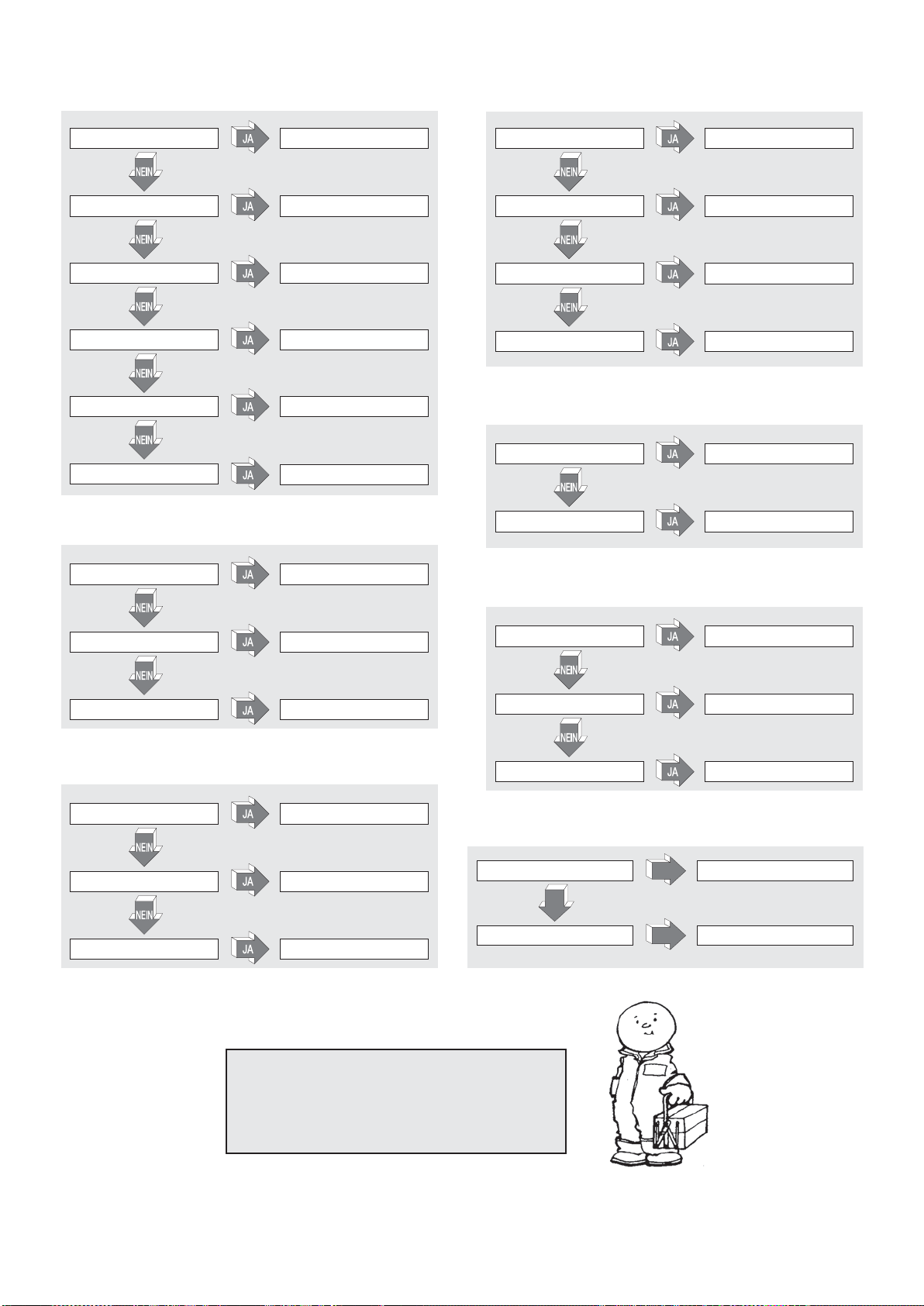
BESTIMMUNG DER SCHÄDEN
DER HUBWAGEN SPRINGT NICHT ANGEHOBEN (21.2):
BATTERIE LEER BATTERIE AUFLADEN
MIKRO DEICHSEL BESCHÄDIGT MIKRO AUSWECHSELN
ABSCHMELZSICHERUNG DURCHGEBRANNT ABSCHMELZSICHERUNG AUSTAUSCHEN
HILFSSICHERUNG DURCHGEBRANNT
ZÜNDSCHLÜSSEL DEFEKT
KURZSCHLUß ELEKTRISCHE ANLAGE
SICHERUNG AUSTAUSCHEN
NEUEN SCHLÜSSEL EINSTECKEN
ELEKTRISCHE ANLAGE KONTROLLIEREN
DIE GABELN BLEIBEN NICHT OBEN (26.1):
DIE GABELN WERDEN NICHT ANGEHOBEN (22.1):
HYDRAULISCHES SYSTEM VERLIERT ÖL ANSCHLÜSSE UND DICHTUNGEN PRÜFEN
ÜBERLASTUNG LAST VERMINDERN
BATTERIE LEER BATTERIE AUFLADEN
ES FEHLT ÖL IM TANK ÖL NACHFÜLLEN
DER HUBWAGEN BREMST NICHT (23.1):
BREMSDREHMOMENT TIEF BREMSE NEU EINSTELLEN
BREMSSYSTEM BESCHÄDIGT BREMSE AUSTAUSCHEN
HYDRAULISCHES SYSTEM VERLIERT ÖL
DRUCKVENTIL SCHMUTZIG VENTIL REINIGEN
ZYLINDERDICHTUNGSVERSCHLEIß
ANSCHLÜSSE UND DICHTUNGEN PRÜFEN
DICHTUNGEN AUSTAUSCHEN
DIE MOTORPUMPE SPRINGT NICHT AN (24.1):
MOTORBÜRSTEN VERBRAUCHT
STARTSCHALTER
ELEKTRISCHE ANSCHLÜSSE DEFEKT
MOTORBÜRSTEN AUSTAUSCHEN
STARTSCHALTER AUSTAUSCHEN
ANSCHLÜSSE PRÜFEN
DIE BATTERIE WIRD NICHT GELADEN (25.1):
BATTERIELADER IST NICHT RICHTIG
ANGESCHLOSSEN
BATTERIELADESICHERUNG DEFEKT
HAUPTNETZES DEFEKT
ANSCHLÜSSE PRÜFEN
ABSCHMELZSICHERUNG DES
AUSTAUSCHEN
ABSCHMELZSICHERUNG DES
AUSTAUSCHEN
DAS ANTRIEBSRAD RUTSCHT WEG (34.2):
DIE HÖHE DES ANTRIEBSRADS
IST NICHT KORREKT
NEIN
DAS ANTRIEBSRAD IST
VERSCHLISSEN
JA
DIE EINSTELLUNG DURCHFÜHREN
JA
DEN RING DES ANTRIEBSRADS
AUSTAUSCHEN
ACHTUNG !!!
SOLLTE KEINE DER VORGESCHLAGENEN LÖSUNGEN ZUR
BEHEBUNG DES SCHADENS BEITRAGEN, DEN HUBWAGEN
ZUM NÄCHSTEN KUNDENDIENST BRINGEN.
16

SUMARIO (1.1)
Q kg 1200 1200 1200 1200 1200 1200 1200
c mm 600 600 600 600 600 600 600
x mm 780 780 780 780 780 780 780
y mm 1234 1234 1234 1234 1234 1234 1234
kg 530 545 578 570 585 618 615
kg 543/1187 558/1187 591/1187 583/1187 598/1187 631/1187 628/1187
kg 368/162 383/162 416/162 408/162 423/162 456/162 453/162
b
10
mm 565 565 565 565 565 565 565
b
11
mm 410 410 410 410 410 410 410
h1mm 1787 1987 2250 1787 1987 2250 1965
h
2
mm - - 80 - - 80 1402
h
3
mm 2410 2810 3410 2410 2810 3410 2810
h
4
mm 2992 3392 3916 2992 3392 3916 3372
h
5
mm - - - - - - -
h
14
mm 915/1310 915/1310 915/1310 960/1330 960/1330 960/1330 960/1330
h
13
mm 90 90 90 90 90 90 90
l
1
mm 1760 1760 1760 1760 1760 1760 1760
l
2
mm 609 609 609 609 609 609 609
b
1
mm 800 800 800 800 800 800 800
s/e/l mm 70/150/1150 70/150/1150 70/150/1150 70/150/1150 70/150/1150 70/150/1150 70/150/1150
b
3
mm 650 650 650 650 650 650 650
b
5
mm 560 560 560 560 560 560 560
m
2
mm 20 20 20 20 20 20 20
A
st
mm 2210 2210 2210 2210 2210 2210 2210
W
a
mm 1430 1430 1430 1430 1430 1430 1430
km/h 4,7/5,2 4,7/5,2 4,7/5,2 4,7/5,2 4,7/5,2 4,7/5,2 4,7/5,2
m/s 0,11/0,19 0,11/0,19 0,11/0,19 0,11/0,19 0,11/0,19 0,11/0,19 0,10/0,18
m/s 0,12/0,15 0,12/0,15 0,12/0,15 0,19/0,19 0,19/0,19 0,19/0,19 0,16/0,14
% 5/10 5/10 5/10 5/10 5/10 5/10 5/10
kW 0,7 0,7 0,7 0,7 0,7 0,7 0,7
kW 2,2 2,2 2,2 2,2 2,2 2,2 2,2
V/Ah 24/85 (C20) 24/85 (C20) 24/85 (C20) 24/118 (C5) 24/118 (C5) 24/118 (C5) 24/118 (C5)
kg 38 38 38 78 78 78 78
kWh/h 0,9 0,9 0,9 0,9 0,9 0,9 0,9
dB(A) 62 62 62 62 62 62 62
*G=Goma, P=Polìuretano, N=Nylon
CARACTERISTICAS TECNICAS.....................................................s.17
DECLARACIÓN DE EMISIÓN DE VIBRACIONES..........................s.17
EMPLEO DE LA MÁQUINA..............................................................s.17
DESCRIPCIÓN DE LA CARRETILLA ..............................................s.17
DISPOSITIVOS DE SEGURIDADS .................................................s.17/18
PLACAS ...........................................................................................s.18
TRANSPORTE Y PUESTA EN MARCHA ........................................s.18
BATERÍA...........................................................................................s.18
UTILIZACIÓN ...................................................................................s.18/19
MANUTENCIÓN...............................................................................s.19
BÚSQUEDA DE LAS AVERÍAS........................................................s.20
CARACTERISTICAS TECNICAS (3.46)
1.1 FABRICANTE PR INDUSTRIAL PR INDUSTRIAL PR INDUSTRIAL PR INDUSTRIAL PR INDUSTRIAL PR INDUSTRIAL PR INDUSTRIAL
1.2 MODELO GX 12/25 III ED. BASIC GX 12/29 III ED. BASIC GX 12/35 III ED. BASIC GX 12/25 III ED. EVO GX 12/29 III ED. EVO GX 12/35 III ED. EVO GX 12/29 III ED. FL EVO
1.3 SISTEMA PROPULSOR ELECTRICO ELECTRICO ELECTRICO ELECTRICO ELECTRICO ELECTRICO ELECTRICO
1.4 SISTEMA DE CONDUCCIÓN ACOMPAÑAMIENTO ACOMPAÑAMIENTO ACOMPAÑAMIENTO ACOMPAÑAMIENTO ACOMPAÑAMIENTO ACOMPAÑAMIENTO ACOMPAÑAMIENTO
1.5 CAPACIDAD DE CARGA
1.6 BARICENTRO
DESCRIPCIÓNPESOS
1.8 DISTANCIA ENTRE EJE RUEDAS DE CARGA Y BASE HORQUILLA
1.9 DISTANCIA ENTRE EJES DE RUEDAS ANTERIORES Y POSTERIORES
2.1 PESO EN SERVICIO CON BATERÍA (Ver línea 6,5)
2.2 CARGA EN EJES CON CARGA, ANTERIOR/POSTERIOR
2.3 CARGA EN EJES SIN CARGA, ANTERIOR/POSTERIOR
3.1 NEUMÁTICOS * G+P/P G+P/P G+P/P G+P/P G+P/P G+P/P G+P/P
3.2 DIMENSIÓN RUEDAS ANTERIORES (Ø x anchura) 250x76 250x76 250x76 250x76 250x76 250x76 250x76
3.3 DIMENSIÓN RUEDAS POSTERIORES (Ø x anchura) 82x70 82x70 82x70 82x70 82x70 82x70 82x70
3.4 DIMENSIÓN RUEDAS LATERALES (Ø x anchura) 100x38 100x38 100x38 100x38 100x38 100x38 100x38
3.5 CANTIDAD RUEDAS (x=DE TRACCIÓN) ANT./POST. 1x+1/2 1x+1/2 1x+1/2 1x+1/2 1x+1/2 1x+1/2 1x+1/2
3.6 DISTANCIA ENTRE RUEDAS ANTERIORES
BASTIDOR/RUEDAS
3.7 DISTANCIA ENTRE RUEDAS POSTERIORES
4.2 ALTURA, MONTANTE CERRADO
4.3 ELEVACIÓN LIBRE
4.4 ALTURA ELEVACIÓN
4.5 ALTURA, MONTANTE EXTRAIDO
4.6 ELEVACIÓN INICIAL
4.9 ALTURA DEL TIMÓN EN POSICIÓN DE CONDUCCIÓN MÍN./MÁX.
4.15 ALTURA HORQUILLAS BAJAS
4.19 LONGITUD TOTAL
4.20 LONGITUD GRUPO MOTRIZ
4.21 ANCHURA TOTAL
DIMENSIONES
4.22 DIMENSIÓN HORQUILLAS
4.24 ANCHO FRONTAL HORQUILLAS
4.25 ANCHURA HORQUILLAS
4.32 HUELGO HORQUILLAS-PAVIMENTO (EN PUNTO CENTRAL ENTRE RUEDAS ANT. Y POST.)
4.34 ESPACIO OPERATIVO NECESARIO PARA PALLETS 800x1200 EN POS. LONGITUDINAL
4.35 RADIO DE GIRO
5.1 VELOCIDAD DE TRASLACIÓN, CON/SIN CARGA
5.2 VELOCIDAD DE ELEVACIÓN, CON/SIN CARGA
5.3 VELOCIDAD DE BAJADA, CON/SIN CARGA
ES
5.8 RAMPA, CON/SIN CARGA
PRESTACION
5.10 FRENO DE SERVICIO ELECTRICO ELECTRICO ELECTRICO ELECTRICO ELECTRICO ELECTRICO ELECTRICO
6.1 POTENCIA MOTOR DE TRACCION
6.2 POTENCIA MOTOR DE ELEVACIÓN
6.4 TENSIÓN BATERÍA, CAPACIDAD NOMINAL
6.5 PESO BATERÍA
MOTORES
ELÉCTRICOS
6.6 CONSUMO DE ENERGÍA SEGUN CICLO VDI
8.4 RUIDO (EN EL OÍDO DEL OPERADOR)
ES
DECLARACIÓN DE EMISIÓN DE VIBRACIONES
Valores de emisión de vibraciones declarados de conformidad con la normativa EN 12096
(33.2)
Superficie de ensayoDescripción Valor Norma Europea (EN)
Valor de emisión de
vibraciones medido, a (m/s
Incertidumbre, K (m/s
Valor de emisión de
vibraciones medido, a (m/s
Incertidumbre, K (m/s
Valor de emisión de
vibraciones medido, a (m/s2)
Incertidumbre, K (m/s
Valor de emisión de
vibraciones medido, a (m/s
Incertidumbre, K (m/s
2
)
2
)
2
)
2
)
0.71
2
)
0.68
2.3
2
)
0.6
0.77
0.39
1.02
2
)
0.08
EN ISO 20643
(Mano-Brazo)
EN ISO 20643
(Mano-Brazo)
EN 13059
(Cuerpo completo)
EN 13059
(Cuerpo completo)
Pavimento de
cemento liso
industrial
En pista de ensayo
según EN 13059
Pavimento de
cemento liso
industrial
En pista de ensayo
según EN 13059
Valores determinados de conformidad con EN ISO 20643 y EN 13059.
EMPLEO DE LA MÁQUINA (4.1)
Esta máquina ha sido proyectada para el transporte y la elevación de unidades de carga, sobre pisos lisos y sin asperidades. Sobre el chasis se encuentra una placa de identificación que, indica la
carga útil de levantamiento, la cual, no deberá superarse nunca para la seguridad del personal y para no dañar el vehículo. Les aconsejamos cumplir rigurosamente con las disposiciones
antinfortunio y con aquellas relativas al funcionamiento y a la manutención. Qualquier montaje de herramientas accesorias sobre la máquina, deberá ser autorizado por la Casa Constructora.
DESCRIPCIÓN DE LA CARRETILLA (5.16) (ver fig. 1)
Esta carretilla es un elevador eléctrico a horquilla con dirección a timón, ideal para el almacenamiento y para el transporte de unidades de carga, en trayectos planos y privos de asperidades. Los
órganos de mando son bien visibles y pueden maniobrarse con comodidad. El elevador está conforme a todas las normas actuales de confort y seguridad CE.
El dibujo muestra las características principales:
1) TIMON DE DIRECCION 2) MÓTORUEDA 3) CENTRALITA HIDRAULICA 4) DESBLOQUEO MANUAL HORQUILLA 5) HORQUILLA LEVANTAMIENTO 6) SEGUNDA ETAPA 7) CHASIS
8) CILINDRO LEVANTAMIENTO 9) INTERRUPTOR GENERAL 10) TARJETA ELECTRÓNICA CONTROL HORQUILLA (EVO) 11) TARJETA ELECTRONICA 12) RUEDA ESTABILIZADORA
13) CÁRTER 14) VÁLVULA PARACAÍDAS 15) BATERIA 16) ELECTROFRENO 17) RODILLOS DE CARGA 18) PROTECCIÓN MANOS 19) RECTIFICADOR 20) CILINDRO ELEVACION
HORQUILLA (sölo versiön Free Lift) 21) CILINDRO ELEVACION MECANISMO DESLIZANTE INTERNO (sölo versiön Free Lift)
DISPOSITIVOS DE SEGURIDAD (6.12) (ver fig. 1)
1) INTERRUPTOR GENERAL (ref. 9) 2) ELECTROFRENO (ref. 16) 3) VÁLVULA PARACAIDAS (ref. 14) 4) VÁLVULA DE MÁXIMA PRESIÓN 5) PROTECCIONES PARACHOQUES: sirven para proteger de
los choques la rueda motriz (ref. 2), las ruedas laterales estabilizadoras (ref. 12) y los rodillos de carga anteriores (ref. 17); por lo tanto, en caso de accidente los píes y la carga están salvaguardados.
6) PALPADQR "HOMBRE MUERTO" (ref. 2 / Fig. 3): es un interruptor de seguridad situado sobre el timón de dirección y protege el conductor contra los choques durante la marcha atrás. 7) PROTECCION
MANOS (ref. 18) 8) DISPOSITIVO DE DESBLOQUEO MANUAL DE LA HORQUILLA (RIF. 4)
Estructura (7.10)
El montante de elevación con las patas y el capó, forman una estructura soldada muy rígida (ref. 7). Las horquillas están guiadas con precisión por 4 rodillos que se deslizan por toda la altura del
montante. La rueda motriz, la rueda giratoria y dos rodillos, garantizan a la carretilla una grande estabilidad con 4 puntos de apoyo. Los cárter (ref.13), que pueden abrirse fácilmente, consienten de
tener una buena accesibilidad a todos los grupos para el servicio de asistencia.
Tracción (8.4)
El grupo de tracción acciona la rueda motriz por medio de engranajes cónicos y cilíndricos. El sentido de la marcha se invierte accionando las mariposas situadas sobre el timón de dirección (ref. 1 / fig. 3)
Timón (9.12) (ref.1/fig.1)
La carretilla la puede conducir un conductor caminando a pié.
El ángulo de viraje es de 210°. El timón trabaja directamente con la rueda motriz, por lo tanto, para cambiar la dirección es necesario girarlo en el sentido deseado. Para poner en función la
carretilla (ver fig. 2) se debe tener el timón en la posición central (pos. B), mientras que para pararlo, se debe colocar en la posición superior (pos. A) o bien en la posición inferior (pos. C). Cuando
se suelta el timón este vuelve automáticamente a la posición superior (pos. A) y funciona como freno de aparcamiento.
Cuando en el modo operativo “velocidad reducida”, el manillar está en la posición superior (A) o en la inferior (C) puede presionarse la tecla “velocidad reducida” (ref. 8 de Fig. 3); en este caso, el
regulador de marcha (ref. 1 de Fig. 3) permite mover el carro a velocidad reducida.
17

Frenos (10.7)
Es el motor el que realiza el frenado de servicio, soltando el acelerador. El freno electromagnético actúa como freno de estacionamiento y como freno de emergencia. El frenado de emergencia se
realiza llevando el timón a la posición superior (pos. A) o a la posición inferior (pos. C) (ver fig. 2). Al desconectar la instalación eléctrica, el freno electromagnético actúa como freno de estacionamiento.
Instalación hidráulica (11.11)
Para levantar o bajar las horquillas, es suficiente actuar con los pulsadores de mando (ref. 4,5 / fig. 3) del grupo timón de manera que la motobomba (ref. 3/ fig.
1) mande el aceite hidráulico del tanque al cilindro de levantamiento.
La energía necesaria para el trabajo efectivo la procura la batería (ref. 15 / fig. 1).
En el caso de una falla en el sistema eléctrico o el agotamiento de la energía almacenada en la batería mientras la carretilla ha horquillas elevadas, usted puede
hacerlas más baja para mover el carro pulsando el sistema de desbloqueo manual (RIF.4/FIG.1) instalado en el solenoide.
En la instalación hidráulica han sido instaladas dos válvulas de seguridad:
a) Válvula sistema prevención de caídas: evita que la carga se caiga de improviso, en caso de ruptura del sistema hidráulico y está integrada en el cilindro
elevador.
b) Válvula de máxima presión, esta está integrada en la motobomba y protege el sistema mecánico e hidráulico contra las sobrecargas.
Instalación eléctrica (12.9)
Construída según las normas en vigor, está constituída por un variador electrónico (ref. 11 / fig. 1) programable (dotado con todas las seguridades y
regulaciones) y con órganos de mando que se pueden maniobrar desde la cabeza del timón. Las conexiones están protegidas contra el aflojamiento
accidental. Los conductores de cobre son muy flexibles y tienen una sección adecuada a las condiciones de funcionamiento y a las influencias externas que
pudieran verificarse. Todos los componentes eléctricos han sido montados de manera de asegurar el buen funcionamiento y facilitar la manutención.
PLACAS (13.13) (ver fig. 4)
Sobre la máquina son visibles las siguientes placas: A) Placa de identificación del tipo de vehículo. B) Placa batería. C) Placa diagrama de carga según la altura de levantamiento y posición del
baricentro de carga de las horquillas. D) Placas indicantes los puntos de embragadura. E) Placas peligro aplastamiento píes. F) Placa de usos prohibidos. G) Placa: leer manual de instrucciones.
H) Placa que indica la altura a la que está aproximadamente a la horquilla elevada I) Identificador pulsador “marcha a velocidad reducida”
No se deben, absolutamente, quitar las placas de su sitio ni volverlas ilegibles.
IMPORTANTE: ESTA PROHIBIDO SUPERAR LA CARGA UTIL INDICADA EN LA PLACA TIPO C, ADJUNTA A LA MÁQUINA EN EL ACTO DE VENTA Y QUE CITAMOS SEGUIDAMENTE:
El presente diagrama ilustra la relación existente entre la carga máxima elevable y la relativa altura máxima desde el suelo, en las operaciones de carga y descarga de un pallet de una
estantería.
El esquema de la horquilla, que se puede ver esquematizada aquí al lado, indica la posición del baricentro de la carga que, debe ser distribuída lo más uniformemente posible por toda
la largura de la misma horquilla.
TRANSPORTE Y PUESTA EN MARCHA
Transporte (14.10)
Para transportar la carretilla están previstos dos puntos de embragadura, indicados por las placas tipo "D" (Fig. 4), mientras que el peso de la misma está indicado sobre la placa de identificación
tipo "A" (Fig. 4).
Se recomienda quitar la protección de las manos superior (Ref. 18, Fig. 1) antes de realizar las maniobras de enganche con los accesorios para evitar su rotura, volviendo a instalar la misma en su
posición antes de poner la máquina en servicio nuevamente.Mientras se conduce es preciso asegurarse de que la carrettilla sea bien enganchada, de manera que no pueda volcarse. Asegurarse
de que ningùn acido o vapor se salga de la bateria (si està).
Puesta en marcha (15.1)
Antes de poner en marcha la máquina, controlar que todas las partes estén en perfectas condiciones, verificar el funcionamiento de todos los grupos y la integridad de los dispositivos de seguridad.
Mover la carretilla con la corriente de la batería y nunca con la corriente alternada rectificada, para no dañar los componentes eléctricos.
BATERÍA (16.7)
Instrucciones, medidas de seguridad y manutención.
La inspección, la carga y el cambio de la batería, lo debe efectuar el personal autorizado, siguiendo las instrucciones para el uso del constructor de la misma. Está prohibido fumar y tener cerca de
la carretilla y del aparato de carga, material inflamable o que provoque chispas. El ambiente debe estar bien ventilado. Para una buena manutención, los tapones de los elementos deben estar
secos y limpios. Eliminar el ácido que pudiera haber salido, untar los bornes con un poco de vaselina y apretarlos. El peso y las dimensiones de la batería pueden influir sobre la estabilidad de la
carretilla, por lo tanto, si se monta una batería diferente a la standard es aconsejable interpelar la CASA CONSTRUCTORA para la autorización necesaria.
La carretilla cuenta con un indicador del estado de su batería. Este indicador se enciende cuando se enciende la máquina y se apaga automáticamente cuando la máquina se pone fuera de
servicio, volviendo a encenderse apenas se usa nuevamente. El LED verde indica que la carga de la batería es suficiente. Un nivel de carga de la batería considerado insuficiente se reconoce al
encenderse el LED amarillo: en estas condiciones la carga residual de la batería resulta suficiente para ejecutar solamente algunos ciclos. Cuando la carga es menor del 20% se enciende el LED
rojo: en estas condiciones será imposible elevar la carga pero la máquina podrá trasladarse para llegar al punto de recarga (toma de corriente). El indicador se activa incluso durante la operación
de recarga, indicando el nivel de carga de la batería durante su ejecución
Carga de la batería
Antes de comenzar la carga, verificar la integridad de los conductores. Conectar el enchufe del cargador de la batería (A) a la red (Fig. 3). Cuando el ciclo de carga concluye, el cargador de la
batería abre el circuito para interrumpir el paso de la corriente y se enciende el piloto verde para indicar la condición. Desenchufar el enchufe (A) de la red. Un ciclo de carga normal requiere entre
10 y 12 horas. Se recomienda recargar la batería al final del turno de trabajo en que debe utilizarse la carretilla. La carga de batería está concebida para asegurar una carga de mantenimiento, por
un cierto periodo de tiempo, después de la carga completa. No existe el riesgo de sobrecarga, por lo tanto, no es necesario desconectar la carga de batería después de la recarga completa.
No descargar nunca completamente las baterías y evitar las cargas incompletas. Dejar siempre que sea la carga de batería a señalar el final de la carga.
ATENCION: Descargar excesivamente las baterías significa reducirles la vida.
Cambio de la batería (17.4)
a) Quitar la cubierta posterior; b) Desconectar los cables de los polos de la batería; c) Extraer la batería; d) Volver a montar la batería siguiendo el orden inverso, fijarla en su alojamiento y
conectarla correctamente.
(Utilizar siempre una batería del mismo tipo de aquella substituída).
IMPORTANTE: EMPLEAR CON CUIDADO EL ACIDO SULFÚRICO, ES TÓXICO Y CORROSIVO; ATACA LA PIEL Y LOS VESTIDOS QUE, EVENTUALMENTE, DEBERÁN SER LAVADOS
CON JABÓN Y AGUA ABUNDANTES. !EN CASO DE ACCIDENTE CONSULTAR UN MÉDICO!
Cuando se sustituye una batería ha de entregarse la batería vieja al centro de recogida y tratamiento especializado más cercano.
Control Batería
Leer atentamente las instrucciones de uso y manutención del Constructor de la batería. Controlar que no haya corrosión, que haya vaseline sobre los polos y que el ácido llegue a 15 mm. por
encima de las placas. Se los elementos están descubiertos, restaurar el nivel con agua destilada. Medir la densidad del electrólito con un densímetro para controlar el nivel de carga.
UTILIZACIÓN (18.17)
El conductor tiene que desarrollar las siguientes instrucciones de empleo en la posición de mando, de manera de quedarse lejano de las zonas peligrosas (como mástils, horquillas, cadenas,
roldanas, ruedas catalinas y estabilizadoras y cualquier otro órgano en movimiento), que puedan implicar el achatamiento de las manos y/o de los pies.
Normas de seguridad
La carretilla debe utilizarse en conformidad a las siguientes normas:
El operador de la máquina debe ser debidamente capacitado en la materia (formación/training específico), conocer las instrucciones de uso del vehículo perfectamente y usar
indumentaria de trabajo apta y un casco. El conductor, responsable de la carretilla, debe impedir la dirección del vehículo a personas no encargadas y evitar que personas ajenas
suban encima de las horquillas o de la plataforma.
Durante la dirección, el operador debe regular la velocidad en curva, en pasajes estrechos, puertas o suelos irregulares. Debe alejar, de la zona en donde la carretilla se mueve,
a las personas no encargadas y avisar inmediatamente si hubieran personas en peligro; en el caso que, no obstante la advertencia, hubieran todavía personas en la zona de
trabajo, el conductor está obligado a parar inmediatamente la carretilla.
Está prohibido detenerse en las zonas en donde hayan partes en movimiento y subir encima de las partes fijas de la carretilla.
El conductor debe evitar las paradas bruscas y las inversiones de marcha veloces.
En caso de subida o bajada, con inclinación máxima cosentida, el conductor debe tener la carga en la parte trasera de las horquillas y reducir la velocidad.
Durante la dirección del vehículo, el conductor debe prestar atención a tener una buena visibilidad y el espacio libre durante la marcha atrás.
Si la carretilla debe ser transportada en ascensores, debe entrar con las horquillas de carga por delante (cerciorarse antes que el ascensor tenga una carga útil suficiente).
Está absolutamente prohibido poner fuera de servicio o desmontar los dispositivos de seguridad. Si la carretilla trabaja en ambientes con un alto riesgo de incendios o de explosiones,
esta debe ser aprobada para un tipo tal de utilización.
La carga útil de levantamiento de la carretilla no debe, en ningún caso, ser superada. El conductor debe asegurarse de que la carga esté bien colocada y en orden perfecto sobre
las horquillas; no sobresalir con la carga por más de 50 mm.desde la extremidad de las mismas.
Está prohibido mover la carretilla con las horquillas en posición alta, está consentido solamente durante las maniobras necesarias para depositar o retirar unidades de carga.
Antes de comenzar el trabajo, el conductor de la carretilla deberá controlar:
- el buen funcionamiento del freno de servicio y de aparcamiento;
- que las horquillas de carga estén en condiciones perfectas;
- que las ruedas y los rodillos estén íntegros;
- que la batería esté cargada, bien sujeta y los elementos bien secos y limpios;
- que todos los dispositivos de seguridad sean eficientes.
Interrumpa el uso del carro cuando el indicador de la bateria (ref. 7/fig. 3) se encuentre en torno al 20% de carga disponible, y pongalo a recargar.
La carretilla debe ser siempre utilizada o aparcada al amparo de la lluvia y de la nieve y de todos modos no debe ser empleada en zonas muy húmedas.
Temperatura de uso -10°, +40°.
La carretilla no debe usarse como medio de tracción de remolques u otras carretillas
Es obligatorio señalar todo daño, anomalía, funcionamiento defectuoso y condición irregular de cualquier tipo al personal responsable. Queda terminantemente prohibido usar la
carretilla hasta que se repare debidamente
Un operador que no posee la competencia ni la especialización necesarias no puede considerarse autorizado a realizar trabajos de reparación de la carretilla y nunca debe modificar
ni desactivar los interruptores y/o dispositivos de protección destinados a garantizar la seguridad por ningún motivo, sin excepción
18

LA CASA CONSTRUCTORA NO SE HACE CARGO DE NINGÚN GRAVAMEN RELATIVO A AVERÍAS O INFORTUNIOS DEBIDOS A INCURIA, INCAPACIDAD, INSTALACIÓN POR PARTE DE
TÉCNICOS NO CAPACITADOS O POR UTILIZACIÓN IMPROPIA DE LA CARRETILLA.
Trasladar
Antes de mover la carretilla, controlar el buen funcionamiento del avisador acústico, del freno y que la batería esté completamente cargada. Girar la llave en posición 1 y colocar el timón en la posición
de traslación. Girar lentamente el regulador y dirigirse hacia la dirección de trabajo deseada. Para frenar o parar completamente, girar el regulador en el sentido contrario al de la marcha. Con la
carretilla hay que virar siempre con delicadeza porque, los movimientos bruscos son la causa de situaciones peligrosas (de manera particular cuando la carretilla se mueve con una velocidad alta).
Moverse siempre con la carga en posición baja, reducir la velocidad en los puntos estrechos y cuando se hace una curva.
Apilar
Moverse con atención cuando se está cerca de una estantería con la carga en posición baja.
Estar seguros de que las patas de la carretilla tengan un pasaje libre debajo de los pallets o en la estantería. La mejor manera es la de poner en línea perfecta el lado del pallet que se debe levantar
con el último que está en la estantería, tomándolo como punto de referencia. De esta manera el trabajo de apilaje y de descarga será más fácil.
Levantar la carga hasta que la misma supere libremente el nivel del plano de almacenamiento.
Moverse lentamente hacia adelante y pararse cuando la carga está encima de la estantería; en este momento bajar las horquillas de manera que puedan liberarse del pallet sin forzar el estante que
está debajo. Controlar que la carga esté colocada de manera segura.
Moverse lentamente hacia atrás, prestando atención a que el pallet quede bien apilado.
Bajar las horquillas en la posición de traslación (fig. 6)
Descargar
1) Con las horquillas en la posición baja y perpendicular, acercarse a la estantería y entrar por debajo del último pallet. 2) Volver atrás con las horquillas fuera del pallet. 3) Levantar las horquillas
hasta la altura deseada y lentamente, moverse hacia el pallet que se debe descargar. Al mismo tiempo, prestar atención a que las horquillas entren por debajo del pallet sin ninguna dificultad y que
la carga esté colocada de manera segura encima de las horquillas. 4) Levantar las horquillas hasta que el pallet se encuentre por encima del nivel del estante. 5) Moverse lentamente hacia atrás en
el pasillo; 6) Bajar la carga lentamente y al mismo tiempo, prestar atención a que las horquillas no encuentren obstáculos durante la bajada.
Condiciones para el uso a velocidad reducida ("tortuga")
Para su uso en espacios reducidos o para la manipulación de mercancías delicadas con precisión y seguridad, se puede recurrir al uso en modalidad "tortuga". La modalidad tortuga sólo se puede
utilizar con el control del timón completamente aliviado. Para las operaciones en velocidad reducida mantenga pulsada la tecla adecuada (rif.8/fig.3) que muestra el pictograma de una tortuga y operar
los controles para la traslación y el movimiento de la horquilla como se hace en las operaciones en modo estándar.
ATENCIÓN: Comparar siempre el peso de la carga con la carga útil de levantamiento relativa a la altura indicada en la placa apropiada.
ATENCION: cuando se levanta la carga durante los movimientos de viraje y de frenada, estos deben ser efectuados lentamente y con mucha atención.
Bloqueo de la elevación (28.2)
La carretilla está dotada de un dispositivo automático que bloquea la elevación si las baterías alcanzan un nivel de descarga superior al 80%. El LED rojo del indicador del estado de la baterÌa indica
que el dispositivo está funcionando. Si este dispositivo interviene es necesario llevar la carretilla a la zona de recarga y actuar como se describe en el párrafo “carga de las baterías”.
Órganos de mando (19.13) (fig. 3)
1. Regulador de marcha; 2. Palpador “hombre muerto”; 3. Tecla del dispositivo indicador acústico; 4. Pulsador levantamiento; 5. Pulsador descenzo; 6. Interruptor general; 7. Señalador condiciones
batería 8. Pulsador “tortuga” (velocidad reducida) 9. Visualización señalador condiciones batería y Cuenta horas
MANUTENCIÓN (20.14)
La manutención debe ser efectuada por el personal especializado. La carretilla debe ser sometida, al menos una vez al año, a un control general. Después de cada manutención, debe verificarse el funcionamiento
de la carretilla y de los dispositivos de seguridad. Someter la carretilla a inspecciones periódicas para no incurrir en paradas de la máquina o en peligros para el personal. (ver tabla manutención)
Tabla de manutención
ELEMENTO CONTROLES
ESTRUCTURA Y HORQUILLAS
FRENOS
RUEDAS
TIMON
SISTEMA ELECTRICO
SISTEMA HIDRAULICO
Control elementos portantes
Control apretamiento pernos y tornillos
Control topes y juegos horquillas
Control functionamiento
Control desgaste ferodo
Control potencia de frenada
Control del juego (áprox. 0,4 mm)
Control desgaste
Control juego cojinetes
Control sujeción
Control del juego
Control movimiento lateral
Control retorno posición vertical
Control desgaste de los telerruptores
Control conexiones, averías de cables
Control interruptor general
Control avisador acústico
Control palpador "hombre muerto"
Control valores fusibles
Control funcionamiento
Control nivel aceite
Control pérdidas y desgaste
conexiones
Cambiar aceite/filtro
Control funcionamiento válvula
limitadora de presion
Control válvula limitadora
de flujo
3 Meses 6 Meses 12 Meses
Tabla de lubricación
PUNTOS
DE LUBRICACION
RUEDAS Y RODILLOS
CADENA DE LEVANTAMIENTO
GUIAS MONTANTES
GRUPO HYDRAULICO
Usar aceite hidráulico excluído el aceite motor y frenos.
Nota: La eliminación de los aceites usados ha de realizarse de conformidad con
las disposiciones aplicables en materia de medio ambiente. Se recomienda
acumular este tipo de fluido en bidones que habrán de entregarse exclusivamente
al centro de recogida y tratamiento especializado más cercano. No descargar el
aceite por tierra o en lugares no idóneos.
Grasa al Litio NLGI-2
Grasa al Litio NLGI-2
Grasa al Litio NLGI-2
Aceite
TIPO
DE LUBRICANTE
ISO VG 32
3 Meses 6 Meses 12 Meses
CADA:
CADA:
CILINDRO
MOTORES ELECTRICOS
BATERIA
INSPECCIONES
Regulación de la altura de la rueda motriz (Fig. 5)
Siga los pasos enumerados a continuación para regular la altura de la rueda
motriz a fin de compensar su desgaste.
1) Desmontar el resguardo inferior.
2) Comprobar que el timón esté en la posición “0”. Introducir un destornillador
en el agujero del suplemento espaciador (Ref. 1) y girar el timón en el sentido
“A”: a un 1/4 de revolución corresponde a una extracción de la rueda motriz
equivalente a 0,5 mm.
3) Quitar el destornillador y girar el timón en el sentido “B” hasta retornar a la
posición “0”.
4) Repetir los puntos 2) y 3) según se requiera. Si la extracción de la rueda motriz
es excesiva, los pasos 2) y 3) deben repetirse en sentido opuesto.
5) Apretar el anillo de seguridad (Ref. 2) contra el suplemento espaciador (Ref.
2). Montar el resguardo.
N.B.: Sustituya la rueda antes de que el espesor de la banda de rodamiento sea
menor de 5 mm.
LIMPIEZA DE LA CARRETILLA: Limpiar las partes de la carretilla, excluídas aquellas
eléctricas y electrónicas, con un paño húmedo. No lavar absolutamente con chorros de
agua directa, vapor o líquidos inflamables. Limpiar las partes eléctricas y electrónicas
con aire comprimido deshumidificado a baja presión (máx. 5 bar), o bien con un pincel
no metálico.
19
ELEMENTO CONTROLES
Control funcionamiento pérdidas y
desgaste empaquetaduras
Control poleas
Control desgaste escobillas
Control relé de arranque motor
Control densidad y nivel electrólito
(no necesario para baterías de gel)
Control tensión elementos
Control sujeción y estanqueidad bornes
Control integridad cables
Engrasar bornes con vaselina
Control conexión a tierra
instalación eléctrica
Control velocidad de traslación subida
y bajada horquillas de carga
Control dispositivos de seguridad
Prueba levantamiento y bajada
con carga nominal
3 Meses 6 Meses 12 Meses
CADA:

BÚSQUEDA DE LAS AVERÍAS
LA MÁQUINA NO ARRANCA (21.2):
BATERÍA DESCARGADA CARGAR LA BATERÍA
NO
MICRO TIMÓN ROTO SUBSTITUIR
NO
FUSIBLE DE POTENCIA QUEMADO
NO
FUSIBLE AUXILIAR QUEMADO SUBSTITUIR
NO
LLAVE ROTA MONTER NY NØGLE
NO
CORTOCIRCUITO INSTALACIÓN
ELÉCTRICA
SI
SI
SUBSTITUIR
SI
SI
SI
CONTROLAR INSTALACIÓN ELÉCTRICA
SI
LAS HORQUILLAS NO QUEDAN LAVANTADOS (26.1):
LAS HORQUILLAS NO SE LEVANTAN (22.1):
PÉRDIDA DE ACEITE SISTEMA
HIDRÁULICO
NO
CARGA EXCESIVA DISMINUIR LA CARGA
NO
BATERÍA DESCARGADA CARGAR BATERIA
NO
FALTA ACEITE EN EL TANQUE AÑADIR ACEITE
SI
SI
SI
SI
CONTROLAR CONEXIONES Y
EMPAQUETADURAS
LA CARRETILLA NO SE FRENA (23.1):
BAJA TORSIÓN DE FRENAJE APRETAR EL FRENO
NO
AVERÍA EN EL SISTEMA FRENANTE
SI
SI
SUBSTITUIR FRENO
PÉRDIDA DE ACEITE EN EL
CIRCUÍTO HIDRÁULICO
NO
VÁLVULA DE PRESIÓN SUCIA LIMPIAR LA VÁLVULA
NO
EMPAQUETADURAS CILINDRO
DESGASTADAS
CONTROLAR CONEXIONES Y
SI
SI
SI
EMPAQUETADURAS
CAMBIAR EMPAQUETADURAS
LA MOTOBOMBA NO ARRANCA (24.1):
ESCOBILLAS MOTOR DESGASTADAS
NO
SWITCH DE ARRANQUE SUBSTITUIR SWITCH
NO
CONEXIONES ELÉCTRICAS
DEFECTUOSAS
SI
SI
SI
SUBSTITUIR ESCOBILLAS
CONTROLAR CONEXIONES
LA MOTOBOMBA NO ARRANCA (24.1):
CARGA DE BATERÍA NO
CONECTADA CORRECTAMENTE
NO
FUSIBLE CARGA DE BATERÍA ROTO
NO
FUSIBLE RED PRINCIPAL ROTO
SI
SI
SI
LA RUEDA MOTRIZ PATINA (34.2):
ALTURA INCORRECTA RUEDA
RUEDA MOTRIZ DESGASTADA
MOTRIZ
NO
SI
SI
CONTROLAR CONEXIONES
SUBSTITUIR FUSIBLE
SUBSTITUIR FUSIBLE
SUSTITUIR ANILLO RUEDA MOTRIZ
REGULAR
ATENCION !!!
SI NINGUNA DE LAS SOLUCIONES SUGERIDAS
SOLUCIONAN L’AVERIA, LLEVAR EL CARRETILLA
A LA ASISTENCIA MAS CERCANA
20

INDICE (1.1)
1.1 CONSTRUTOR PR INDUSTRIAL PR INDUSTRIAL PR INDUSTRIAL PR INDUSTRIAL PR INDUSTRIAL PR INDUSTRIAL PR INDUSTRIAL
Q kg 1200 1200 1200 1200 1200 1200 1200
c mm 600 600 600 600 600 600 600
x mm 780 780 780 780 780 780 780
y mm 1234 1234 1234 1234 1234 1234 1234
kg 530 545 578 570 585 618 615
kg 543/1187 558/1187 591/1187 583/1187 598/1187 631/1187 628/1187
kg 368/162 383/162 416/162 408/162 423/162 456/162 453/162
b
10
mm 565 565 565 565 565 565 565
b
11
mm 410 410 410 410 410 410 410
h
1
mm 1787 1987 2250 1787 1987 2250 1965
h
2
mm - - 80 - - 80 1402
h
3
mm 2410 2810 3410 2410 2810 3410 2810
h
4
mm 2992 3392 3916 2992 3392 3916 3372
h
5
mm - - - - - - -
h
14
mm 915/1310 915/1310 915/1310 960/1330 960/1330 960/1330 960/1330
h
13
mm 90 90 90 90 90 90 90
l
1
mm 1760 1760 1760 1760 1760 1760 1760
l
2
mm 609 609 609 609 609 609 609
b
1
mm 800 800 800 800 800 800 800
s/e/l mm 70/150/1150 70/150/1150 70/150/1150 70/150/1150 70/150/1150 70/150/1150 70/150/1150
b
3
mm 650 650 650 650 650 650 650
b
5
mm 560 560 560 560 560 560 560
m
2
mm 20 20 20 20 20 20 20
A
st
mm 2210 2210 2210 2210 2210 2210 2210
W
a
mm 1430 1430 1430 1430 1430 1430 1430
km/h 4,7/5,2 4,7/5,2 4,7/5,2 4,7/5,2 4,7/5,2 4,7/5,2 4,7/5,2
m/s 0,11/0,19 0,11/0,19 0,11/0,19 0,11/0,19 0,11/0,19 0,11/0,19 0,10/0,18
m/s 0,12/0,15 0,12/0,15 0,12/0,15 0,19/0,19 0,19/0,19 0,19/0,19 0,16/0,14
% 5/10 5/10 5/10 5/10 5/10 5/10 5/10
kW 0,7 0,7 0,7 0,7 0,7 0,7 0,7
kW 2,2 2,2 2,2 2,2 2,2 2,2 2,2
V/Ah 24/85 (C20) 24/85 (C20) 24/85 (C20) 24/118 (C5) 24/118 (C5) 24/118 (C5) 24/118 (C5)
kg 38 38 38 78 78 78 78
kWh/h 0,9 0,9 0,9 0,9 0,9 0,9 0,9
dB(A) 62 62 62 62 62 62 62
*G=Borracha, P=Polìuretano, N=Nylon
CARACTERÍSTICAS TÉCNICAS ....................................................pág.21
DECLARAÇÃO DE EMISSÃO VIBRATÓRIA................................... pág.21
FUNCIONAMENTO DO APARELHO ...............................................pág.21
DESCRIÇAO DA CARRETILHA.......................................................pág.21
DISPOSITIVO DE SEGURANÇA.....................................................pág.21/22
PLAQUETAS....................................................................................pàg.22
TRANSPORTE E FUNCIONAMENTO............................................. pág.22
BATERIA ..........................................................................................pàg.22
USO.................................................................................................. pág.22/23
MANUTEN........................................................................................ pág.23
PORQUE NÃO FUNCIONA..............................................................pág.24
CARACTERÍSTICAS (3.46)
1.2 MODELO GX 12/25 III ED. BASIC GX 12/29 III ED. BASIC GX 12/35 III ED. BASIC GX 12/25 III ED. EVO GX 12/29 III ED. EVO GX 12/35 III ED. EVO GX 12/29 III ED. FL EVO
1.3 PROPULSÃO ELECTRICO ELECTRICO ELECTRICO ELECTRICO ELECTRICO ELECTRICO ELECTRICO
1.4 SISTEMA DE GUIA PASSAGEIRO PASSAGEIRO PASSAGEIRO PASSAGEIRO PASSAGEIRO PASSAGEIRO PASSAGEIRO
1.5 CAPACIDADE
1.6 CENTRO DE GRAVIDADE
DESCRIÇÃOPESOS
1.8 DISTÂNCIA EIXO RODAS DE CARGA DA BASE DO GARFO
1.9 PASSO
2.1 MASSA EM SERVIÇO COM BATERIA (veja a linha 6,5)
2.2 CARGA NOS EIXOS COM CARGA, DIANTEIRA/TRASEIRA
2.3 CARGA NOS EIXOS SEM CARGA, DIANTEIRA/TRASEIRA
3.1 REVESTIMENTO EM BORRACHA * G+P/P G+P/P G+P/P G+P/P G+P/P G+P/P G+P/P
3.2 DIMENSÕES RODAS DIANTEIRAS (Ø x largura) 250x76 250x76 250x76 250x76 250x76 250x76 250x76
3.3 DIMENSÕES RODAS TRASEIRAS (Ø x largura) 82x70 82x70 82x70 82x70 82x70 82x70 82x70
3.4 DIMENSÕES RODAS LATERAIS (Ø x largura) 100x38 100x38 100x38 100x38 100x38 100x38 100x38
3.5 NÚMERO DE RODAS (x=MOTORA) DIANTEIRA/TRASEIRA 1x+1/2 1x+1/2 1x+1/2 1x+1/2 1x+1/2 1x+1/2 1x+1/2
3.6 BITOLA DIANTEIRA
ESTRUTURA/RODAS
3.7 BITOLA TRASEIRA
4.2 ALTURA, MONTANTE FECHADO
4.3 ELEVAÇÃO LIVRE
4.4 ALTURA DE ELEVAÇÃO
4.5 ALTURA, MONTANTE EXTENDIDO
4.6 ELEVAÇÃO INICIAL
4.9 ALTURA DO TIMÃO EM POSIÇÃO DE GUIA MÍN/MÁX
4.15 ALTURA GARFO ABAIXADO
4.19 COMPRIMENTO TOTAL
4.20 COMPRIMENTO UNIDADE MOTORA
4.21 LARGURA TOTAL
DIMENSÕES
4.22 DIMENSÕES GARFO
4.24 LARGURA FRONTAL FORQUILHAS
4.25 LARGURA GARFO
4.32 ESPAÇO LIVRE (METADE DO PASSO)
4.34 CORREDOR DE ARMAZENAMENTO PARA PALETES 800x1200 LONGITUDINAL
4.35 RAIO DE VIRAGEM
5.1 VELOCIDADE DE TRANSLADAÇÃO, COM/SEM CARGA
5.2 VELOCIDADE DE ELEVAÇÃO, COM/SEM CARGA
5.3 VELOCIDADE DE DESCIDA, COM/SEM CARGA
5.8 DECLIVE SUPERAVEL, COM/SEM CARGA
DESEMPENHO
5.10 FREIO DE SERVIÇO ELECTRICO ELECTRICO ELECTRICO ELECTRICO ELECTRICO ELECTRICO ELECTRICO
6.1 POTÊNCIA MOTOR DE TRAÇÃO
6.2 POTÊNCIA MOTOR DE ELEVAÇÃO
6.4 TENSÃO BATERIA, CAPACIDADE NOMINAL
6.5 MASSA BATERIA
MOTORES
ELÉTRICOS
6.6 CONSUMO DE ENERGIA CONFORME CICLO VDI
8.4 RUÍDO NO OUVIDO DO OPERADOR
PT
DECLARAÇÃO DE EMISSÃO VIBRATÓRIA (33.2)
Valores de emissão vibratória declarados conforme à EN 12096
Superfície de testeDescrição Valor Norma européia (EN)
Valor de emissão vibratória
medido, a (m/s
Incerteza, K (m/s
Valor de emissão vibratória
medido, a (m/s2)
Incerteza, K (m/s
Valor de emissão vibratória
medido, a (m/s2)
Incerteza, K (m/s
Valor de emissão vibratória
medido, a (m/s2)
Incerteza, K (m/s
2
)
2
)
2
)
2
)
2
)
0.71
0.68
2.3
0.6
0.77
0.39
1.02
0.08
EN ISO 20643
(Mão-Braço)
EN ISO 20643
(Mão-Braço)
EN 13059
(Corpo inteiro)
EN 13059
(Corpo inteiro)
Piso em concreto
lizo industrial
Em pista de teste
conforme à EN 13059
Piso em concreto
lizo industrial
Em pista de teste
conforme à EN 13059
Valores determinados conforme à EN ISO 20643 e à EN 13059.
FUNCIONAMENTO DO APARELHO (4.1)
Este aparelho foi projetado para a elevação e o transporte de unidades de carga sobre pisos lisos e não áspera. Sobre os chassis se encontra uma placa de identificação que indica a capacidade de
elevação qual não deve nunca ser superada, para a segurança do trabalhador e para manter a integridade do veículo. Aconselhamos de respeitar rigorosamente as normas ante acidentes e aquelas
que requerem a manutenção do aparelho. Qualquer tipo de modificação no aparelho deve ser autorizada pela casa e construção.
DESCRIÇÃO DA CARRETILHA
Esta carretilha é um transpallet eletrônico a garfos com guia a timão, ideal para o armazenamento e o transporte de unidades de carga sobre percursos planos e não áspera. Os comandos são bem
visíveis e acionáveis comodamente. O transpallet è conforme todas as normas atuais de, conforto e segurança CE.
A figura representa as principais características:
1) TIMAO_DE GUIA 2) MOTOR A RODA 3) CENTRAL HIDRÁULICA 4) DISPOSITIVO MANUAL DE LIBERAÇAO GARFO 5) GARFO DE ELEVAÇAO 6) SEGUNDO ESTADIO 7) CHASSIS
8) CILINDRO DE ELEVAÇAO 9) INTERRUPTOR GERAL 10) PLACA ELETRÔNICA DE CONTROLE DO GARFO (EVO) 11) INVERTER 12) RODA ESTABILIZADORA 13) CÁRTER 14) VÁLVULA
PÁRA-QUEDAS 15) BATERIA 16) FREIO ELÉTRICO 17) ROLO DE CARGA 18) PROTEÇÃO PARA AS MÃOS 19) RECTIFICADOR 20) CILINDRO LEVANTAMENTO GARFO (só versão Free
Lift) 21) CILINDRO LEVANTAMENTO SEGUNDA SECÇÃO (só versão Free Lift)
(5.16) (ver fig.1)
DISPOSITIVOS DE SEGURANÇA (6.12) (ver fig.1)
1) INTERRUPTOR GERAL (rif.9) 2) FREIO ELÉTRICO (rif.16) 3) VÁLVULA PARA-QUEDA (rif.14) 4) VÁLVULA DE MÁXIMA PRESSÃO 5) PROTEÇÃO PÁRA-CHOQUE: serve para a proteção
contra batidas da roda motriz (rif.2), e as rodas laterais estabilizadoras (rif.12) em caso de acidentes os pés e a carga são ao seguro. 6) INTERRUPTOR "HOMEM MORTO" (rif.2/fig.3) è um interruptor
de segurança situado no timão de guia. Protege o condutor contra batidas em marcha ré. 7) PROTEÇAO PARAAS MAOS (rif. 18) 8) DISPOSITIVO MANUAL DE LIBERAÇAO GARFO (rif.4)
Estrutura (7.10)
Os garfos de elevação com as pernas e o capo formam uma estrutura soldada de alta resistência e muito rígida. Os rolos anteriores de carga (rif.13) e a roda motriz asseguram um ótimo escorrimento.
Os cárter (rif.7) se pode abrir facilmente consentem um bom acesso a todos os grupos para a assistência.
Tração (8.4)
O grupo de tração aciona a roda motriz através das engrenagens. O sentido de marcha se inverte acionando as fivelas sobre o timão de guia (rif.1/fig.3).
Timão (9.12) (rif.1/fig.1)
O carrinho pode ser guiado por um condutor a pé. O angulo de virada è de 210°.
O timão age diretamente na roda motriz e para trocar de direção deve-se roda-lo no sentido desejado. Para acionar o carrinho (ver fig.2) deve-se segurar o timão na posição central (pos. B), para
para-lo deve-se levar o carrinho para a posição superior (pos. A) ou inferior (pos. C). Quando largar o timão ele voltara para a posição superior (pos. A) automaticamente, e o freio de estacionamento
entrara em função. No modo “tartaruga”, quando o timón estiver na posição superior (pos. A) ou naquela inferior (pos. C), apertando o botão “tartaruga” (ref. 8, fig. 3) e agindo no regulador de marcha
(ref. 1, fig. 3), o carro se move de velocidade reduzida.
Freios (10.7)
A travagem de serviço é efectuada pelo motor, ao deixar o acelerador. O travão electromagnético funciona como travão de estacionamento e travão de emergência. A travagem de emergência
efectua-se colocando o timão para a posição superior (pos.A) ou para a posição inferior (pos.C) (veja fig.2). Se desligar a instalação eléctrica, o travão electromagnético funcionará como travão de
estacionamento.
21

Implanto Hidráulico (11.11)
Para levantar e abaixar as forcas è suficiente, precionar os botões de comando (rif.4,5 / fig. 3) do grupo timão in modo que a bombo motriz (rif.3 / fig.1) mande o oleo hidrulico do tanque ao cilindro
de elevão. A energia necessaria para o trabalho è fornecida da bateria (rif 15/fig.1).
No caso de uma falha no sistema elétrico ou esgotamento da energia armazenada na bateria enquanto o carrinho tem da forquilha levantada, você pode fazê-los ir para baixo para mover o carro,
agindo sobre o sistema de liberação manual (RIF.4/FIG.1) instalado no solenóide.
No implanto hidráulico são instaladas duas válvulas de segurança:
a) válvula pára-quedas, evita que a carga caia de repente, no caso que quebre o sistema.
b) válvula de máxima pressão, integrada à bomba do motor, protege os sistemas mecânico e hidráulico de sobrecargas.
Implanto elétrico (12.9)
Construído segundo as normas em vigor, è constituído de um Variador eletrônico (rif.11/fig.1) dotado de todas as seguranças e regulações, de comandos acionáveis
do painel do timão. As conecções são asseguradas contra o afrouxamento acidental. Os condutores são de cobre e muito flexíveis e tem a sessão ajustada para
as condições de funcionamento e as influências externas que possam verificar-se. Todos os componentes elétricos são montados em modo de assegurar o
funcionamento e facilitar a manutenção.
PLAQUETAS (13.13) (ver fig.4)
Sobre o aparelho são visíveis as seguintes plaquetas:
A) Plaquetas de identificação do tipo de veiculo, indica a capacidade máxima; B) Plaqueta bateria C) Plaqueta diagrama de carga segundo a altura de elevacao
e posição do baricntro do garfo D) Plaquetas que indicam os pontos da braçadeira E) Plaqueta perigo de dano aos pés F) Plaquetas proibido usar
G) Plaqueta consulte o manual H) Plaqueta que indica a altura em que é aproximadamente o garfo levantada I) Placa do botão “tartaruga”
As plaquetas não devem ser retiradas e devem ser mantidas legíveis.
Importante: è proibido superar a capacidade de carga indicada na plaqueta tipo C. E deve ser colada no aparelho no ato da venda.
Este diagrama ilustra o relacionamento entre a carga máxima e a relativa altura máxima do chão nas operações de carga e descarga de um pallet de uma prateleira.
O esquema do garfo esquematizado ao lado, indica a posição do baricentro da carga que deve ser distribuído mais uniformemente possível em todo o garfo.
TRANSPORTE E MEIO DE FUNCIONAMENTO
Trasporte (14.10)
Para transportar o carrinho são previstos três pontos na braçadeira indicada nas plaquetas tipo "D" (fig.) grudadas no aparelho, o peso è indicado na plaqueta de identificação de tipo "A".
Antes da lingagem, aconselhamos de remover a proteção superior das mãos (ref. 18, fig. 1) para não quebrá-la. Remonte a proteção antes de arrancar a máquina.
È aconsehavel, durante o transporte, assegurar firmemente o carrinho para que não emborque. Verifique que da bateria (se estiver presente) não saiam acido ou vapores.
Meio de funcionamento (15.1)
Antes de colocar em função o aparelho controlar que todas as partes estejam em perfeitas condições, verificar o funcionamento e os dispositivos de segurança.
BATTERIA (16.7)
Medida de segurança manutenção
A inspeção, o carregamento e a troca da bateria, devem ser feitos através de operários autorizados seguindo a instrução de uso da casa de construção. È proibido fumar, e deixar material inflamável
perto do carrinho, pode provocar chamas. O ambiente deve ser bem arejado. Para uma boa manutenção as tampas dos elementos devem ser sempre secas e limpas. Eliminar o acido em excesso,
passar um pouco de vaselina nos tornos e aperta-los. O peso e as dimensões da bateria podem influir na estabilidade do carrinho, e se a bateria for diferente da estandard se aconselha de consultar
a CASA DE CONSTRUÇAO para a autorização.
O empilhador é provido de um indicador do estado da bateria que liga ao ligar a máquina. Em caso de inatividade da máquina, o indicador é desligado e ligado novamente quando for utilizada
novamente. O led verde indica que as baterias estão suficientemente carregadas. Quando o nível de carga torna-se insuficiente, a luz amarela é ligada, indicando uma carga ainda insuficiente para
alguns ciclos de trabalho. Quando a carga residual cai abaixo de 20%, a luz vermelha é ligada. Nesta condição a carga não pode ser mais levantada, mas a máquina ainda pode se mover para
alcançar a tomada para se recarregar. O indicador liga também durante a fase de recarga, sinalizando o estado de avanço.
Carga da bateria
Antes de iniciar o carregamento verificar a integridade do condutor. Ligar a tomada do carregador de bateria (A) na rede (veja a fig. 3). M terminar da carga, o carregador interrompe a salda da corrente
e liga o indicador verde. Desligar a tomada (A) da rede. Uma carga normal necessita de 10 a 12 horas. É aconselhável recarregar a bateria no fim do turno de utilização do carro. O carregador foi
feito para assegurar uma carga de manutenção pôr um certo período de tempo, após o carregamento completo. Não existe o risco de sobrecarga, não è necessário desligar o recarregador de bateria
depois da recarga total.
Não descarregar nunca completamente a bateria, evitar cargas incompletas e deixas sempre que seja o recarregador de bateria a determinar o final do carregamento.
ATENÇAO: descarregar excessivamente as baterias reduz a vida das mesmas.
Substituição da bateria (17.4)
a) Remover o resguardo traseiro; b) desligar os fios dos pólos da bateria; c) extrair a bateria; d) Remontar a bateria seguindo a ordem inversa, fixando-a na própria sede e ligando-a correctamente.
(Colocar sempre uma bateria do mesmo tipo da substituída.)
IMPORTANTE : MANUSEAR COM CURA O ACIDO SULFÙRICO, È TOXICO E CORROSIVO. DESTRUI A PELE E OS VESTIDOS, EM CASO NECESSÁRIO DEVERÃO SER LAVADOS COM
SABÃO E ÁGUA CORRENTE EM ABUNDÂNCIA. EM CASO DE ACIDENTES CONSULTAR O MEDICO!!! Em caso de substituição da bateria, entregue a bateria velha para o ponto de recolha
mais próximo.
Observação da bateria
Ler atentamente as instruções de uso e a manutenção do construtor da bateria. Observar a ausência de corrosão, a presença de vaselina, e que o acido esteja 15mm sobre as plaquetas. Se os
elementos estão descobertos, versar água destilada. Medir a densidade do eletrodo com o densímetro para controlar o nível da carga.
UTILIZAÇÃO (18.17)
O condutor devera seguir as seguintes instruções de uso na posição de guia. Devera exercer as seguintes operações, em modo tal de distanciar-se das áreas perigosas para evitar o esmagamento
de mãos e pés, nos quais montados garfos, correntes, rodas motrizes e estabilizador e qualquer outra peça em movimento.
Normas de segurança:
O carrinho deve ser usado conforme as seguintes normas:
a) O operador da máquina deve ser adequadamente treinado, conhecer as instruções de uso do veículo, vestir roupa apropriada e o capacete.
b) O condutor responsável do carrinho deve impedir aos não adaptas a direção do meio, evitar que desconhecidos o pilotem.
c) Durante a guia o operador deve regular a velocidade nas curvas, em lugares estreitos, portas ou pavimento irregular. Deve afastar da zona onde o carrinho se movem os não encarregados, e avisar
imediatamente se tem pessoas em perigo. No caso em que depois do aviso, encontrem-se ainda pessoas na zona de transito o condutor è obrigado a parar imediatamente o carrinho.
d) E' proibido parar na zona em movimento e subir nas partes fixas do carrinho.
e) O condutor deve evitar as paradas bruscas e as inversões de marcha velozes.
f) No caso de subida au descida, com a pendenza max permidida, o condutor deve ter a carga na frente e reduzir a velocidade.
g) Durante a guia o condutor deve prestar atenção e ter uma boa visibilidade, haver o espaço durante a marcha ré.
h) Se o carrinho è transportado no elevador deve entrar com os garfos de carregamento na frente;
i) E absolutamente proibido desmontar ou desligar os dispositivos de segurança. Se o carrinho trabalha em ambiente de risco de acidentes ou de explosão este deve ser aprovado para este tipo de
utilização;
j) A medida máxima do carrinho não pode em algum caso ser superada; O condutor deve assegurar-se que a carga seja bem colocada nos garfos e em perfeita ordem não distanciar alem da sua
extremidade mais de 50mm;
k) E' proibido movimentar o carrinho com as forcas na posição alta, è permitido so nas manobras necessarias a depositar ou retirar a unidade de carga.
l) Antes de começar o trabalho o condutor do carrinho deve controlar:
- o funcionamento dos freios de serviço e de estacionamento;
- que os garfos de carregamento sejam em perfeitas condições;
- que as rodas e os rolos sejam perfeitos;
- que a bateria seja carregada, e os elementos enxutos e limpos;
- que todos os dispositivos de segurança estejam funcionando.
m) Interromper o uso do carrinho quando a bateria esta fraca (20%), e coloca-la para carregar.
n) O carrinho deve ser sempre usado e estacionado fora da chuva, neve e longe de umidade.
o) Temperatura de uso: -10°, +40°.
p) Evite usar o empilhador para reboque, também de outros empilhadores.
q) Informe imediatamente o pessoal responsável sobre qualquer dano, falha ou mal funcionamento. É proibido o uso do empilhador enquanto estiver falhado.
r) O operador desprovido da qualificação necessária não é autorizado para realizar consertos no empilhador, nem também para desativar ou modificar os dispositivos de segurança e os interruptores.
A CASA DE CONSTRUÇÃO NÃO ASSUME NENHUMA RESPONSABILIDADE EM CASO DE INCAPACIDADE DE INSTALAÇÃO DA PARTE DOS TÉCNICOS NÃO HABILITADO À UTILIZAÇÃO
DO CARRINHO.
Deslocamento (ver fig. 6)
Antes de mover o carrinho controlar o funcionamento do sinal acústico, do freio e que a bateria seja carregada completamente. Girar a chave na posição 1 e colocar o volante na posição do movimento.
Girar o regulador delicadamente e dirigir na direção desejada. Para parar completamente girar o regulador no sentido contrario à marcha. Com o carrinho vire delicadamente, os movimentos bruscos
são causas de situações perigosas ( principalmente quando o carrinho se move em alta velocidade) reduzir a velocidade nas curvas.
Empilhar
1)Movimentar-se com atenção perto das estantes com a carga em posição baixa. 2)Tenha certeza que as pernas do carrinho tenham passagem livre embaixo do pallet ou nas estantes. O modo
melhor è de colocar em perfeita linha o lado do pallet que temos que levantar com o ultimo da estante como referimento. Assim empilhar será mais fácil. 3)Levantar a carga ate que esta supere
livremente o nível do plano do estoque. 4)Movimentar-se um pouco para frente e parar quando a carga esta em cima da estante; abaixar os garfos. 5)Dar uma pequena ré 6)Abaixar os garfos em
posição para deslocar (fig. 6).
22

Descarregar
1) Com os garfos em posição baixa e perpendicular chegar perto da estante e entrar embaixo do ultimo pallet 2) Voltar os garfos fora do pallet 3) Levantar os garfos da altura desejada e lentamente
mova-se ate o pallet que deve ser descarregado. Ao mesmo tempo verificar que os garfos entrem sem dificuldades embaixo do pallet e que a carga seja posicionada com segurança. 4) Levantar o
garfo ate a altura da estante 5) Mova-se lentamente para traz 6) Abaixar a carga e no mesmo tempo verificar que os garfos não encontrem obstáculos durante a descida.
Condições para uso em baixa velocidade ("tartaruga")
Para uso em espaços confinados ou para manuseamento de mercadorias delicadas com precisão e segurança, é possível recorrer à utilização em modo "tartaruga". O modo de tartaruga só pode
ser usado com o controle do leme totalmente aliviada. Para o modo de operação em velocidade reduzida pressione e segure a tecla apropriada (rif.8/fig.3), que mostra a imagem gráfica de uma
tartaruga e operar os controles para o deslocamento eo movimento dos garfos como feito em operações de modo padrão.
Atençao: Gonfiandor sempre o peso da carga con a capacidade de elevaçao relativa a alture indicada sobre a plagueta .
Atençao: ihuando a ranga è levandoda o momendo de sterzar e freiar devem ser fei dos lentamente e com mui ta atençao.
Trava de elevação (28.2)
O carro elevador possui um dispositivo automático que trava a elevação se as baterias atingem um nível de
descarga superior a 80%. A ativação do dispositivo é assinalado pelo led vermelho do indicador do estado da bateria.
PAINEL DE CONTROLE (19.13) (fig. 3)
1) Regulador de marcha; 2) Botão “homem morto”; 3) Botão assinalador acústico; 4) Botão elevação; 5) Botão decida; 6) Interruptor general; 7) Sinalizador do estado da bateria 8) Botão
"tartaruga" 9) Indicador de status da bateria Display e horímetro
MANUTENÇÃO (20.14)
A manutenção deve ser efetuada através de operários especializados. O carrinho tem que ser controlado uma vez pôr ano. O carrinho tem que ser controlado uma vez pôr ano; Depois de cada
manutenção tem que ser verificado o funcionamento do carrinho e dos dispositivos de segurança. Controlar o carrinho periodicamente, para evitar dano ao aparelho, ou pôr em perigo o operário! (Ver
tabela de manutenção).
Tabela de manutençào
ELEMENTOS CONTROLE
ESTRUTURA
FREIOS
RODAS
VOLANTE
SISTEMA ELÉTRICO
SISTEMA HIDRÁULICO
Verificar elementos portadores
Verificar parafusos
Verificar os jogos dos garfos
Verificar funcionamento
Verificar gasto ferodo
Verificar a potência da freada
Verificar o jogo (cerca 0,4mm)
Verificar uso
Verificar jogo de almofadinhas
Verificar ancoragem
Verificar o jogo
Verificar o movimento lateral
Verificar o retorno à posição vertical
Verificar gasto telerotor
Verificar conecção, cabos mal funcionantes
Verificar interruptor general
Verificar aviso acústico
Verificar botão "homem morto"
Verificar o valor dos fusíveis
Verificar funcionamento
Verificar nível do óleo
Verificar perdas e gasto
das conecções
Trocar óleo/filtro
Verificar funcionamento válvula
limitadora de pressão
Verificar válvula limitadora
de fluxo
Tabela de lubrifiçào
PONTOS DE
LUBRIFICAÇÃO
RODAS E ROLOS
CORRENTE DE ASCENSÃO
GUIA ASCENDENTE
GRUPO HIDRÁULICO
LUBRIFICAÇÃO
Gordura NLGI-2
Gordura al Litio NLGI-2
Gordura al Litio NLGI-2
ISO VG 32
Óleo,
TIPOS DE
VALIDADE
3 MESES 6 MESES 12 MESES
VALIDADE
3 MESES 6 MESES 12 MESES
ELEMENTOS CONTROLE
CILINDRO
MOTORES ELÉTRICOS
BATERIA
INSPEÇÃO
Regulação da altura da roda motora (fig. 5)
Regule a altura da roda motora de acordo com o procedimento seguinte, para
compensar o desgaste:
1) Desmonte o resguardo inferior.
2) Com o timão em posição “0”, insira uma chave de fenda no furo do separador
(ref. 1) e gire o timão para a direção “A” (1/4 de volta = 0,5 mm de extração da
roda motora).
3) Extraia a chave de fenda e gire o timão para a direção “B” até voltar para a
posição “0”;
4) Repita as operações nos pontos 2 e 3 quantas vezes for necessário. No caso
em que a roda motora estiver para fora demais, repita as operações 2 e 3 girando
para o sentido oposto.
5) Aperte a união (ref. 2) contra o separador (rif. 1) e remonte o resguardo inferior.
OBS: substitua a roda antes que a profundidade do piso esteja abaixo de 5 mm.
Verificar o funcionamento e perdas
(gasto) nos tubos
Controle da polias
Verificar gasto das escovas
Verificação dos relês de accionamento motor.
Verificar densidade e nível do eletrólito
(Não necessário para as baterias de gel)
Controlar a tensão dos elementos
Verificar a ancora e braçadeira
Verificar a integridade dos cabos
Passar vaselina nas braçadeiras
Verificar conexão do sistema elétrico
Verificar a velocidade de translação (subida
descida) dos garfos de carregamento
Verificar os dispositivos de segurança
Provar a levantar e abaixar com carga normal
VALIDADE
3 MESES 6 MESES 12 MESES
Usar o óleo hidráulico exclusivamente no motor e nos freios.
OBS: elimine o óleo usado sempre respeitando o ambiente. Aconselhamos a acumulação
em barris para entrega sucessiva ao ponto de recolha mais próximo. Não jogar o óleo
na terra ou em lugar não adapto.
Limpeza do carrinho: limpar todas as partes do carrinho, menos as partes elétricas ou eletrônicas
com um pano úmido. Não lavar com jatos d'água, vapor ou líquidos inflamáveis. Limpar as
partes elétricas com ar compresso desumidificado, ou com um pincel não metálico.
23
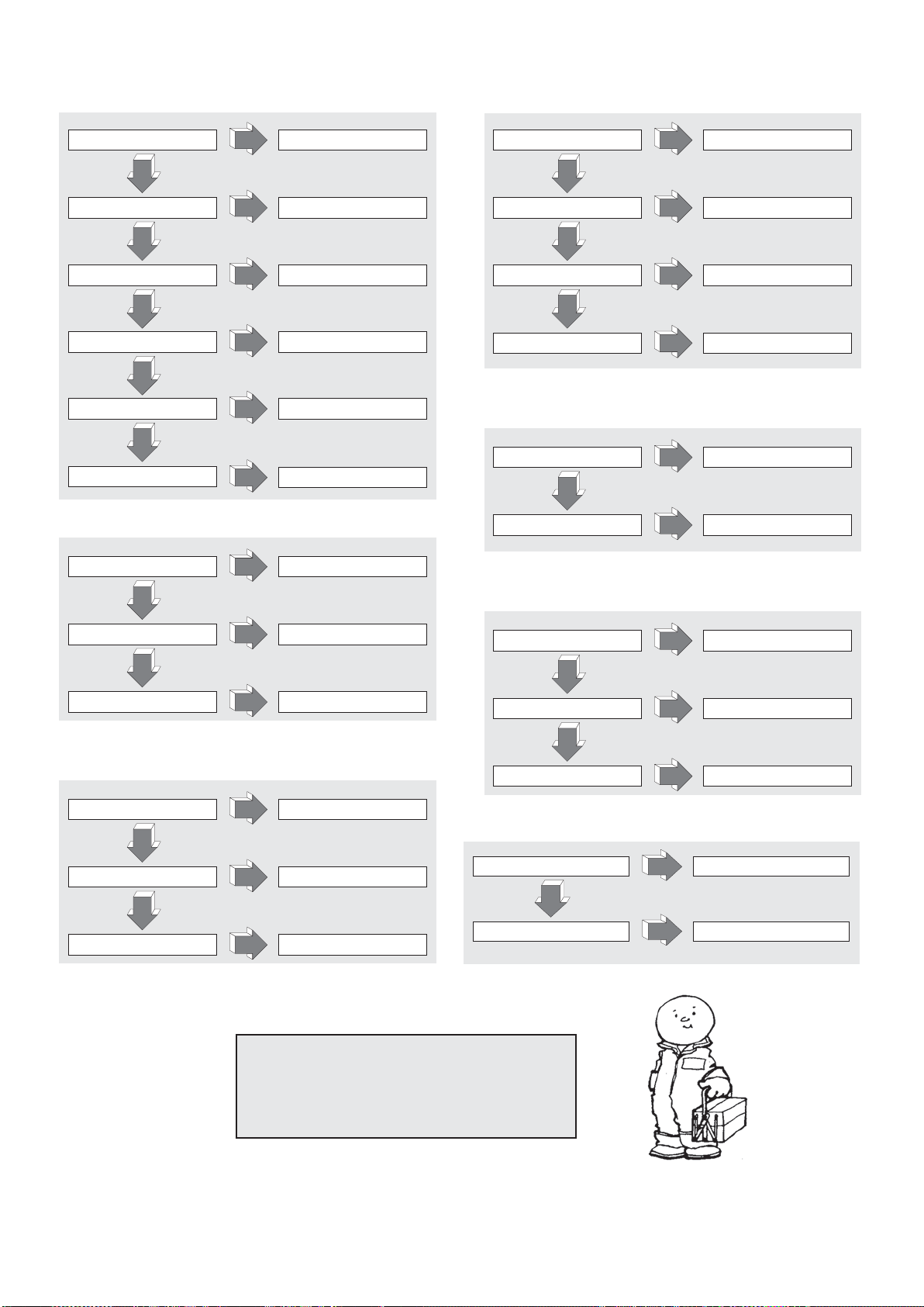
PORQUE NÃO FUNCIONA
O APARELHO NÃO LIGA (21.2):
BATERIA DESCARREGADA CARREGAR A BATERIA
NÃO
MICRO TIMÃO QUEBRADO SUBSTITUIR
NÃO
FUSÍVEIS DE POTÊNCIA
QUEIMADOS
NÃO
FUSÍVEIS AUXILIARES QUEIMADOS
NÃO
CHAVE RODA MONTAR CHAVE NOVA
NÃO
CURTO CIRCUITO DO SISTEMA
ELÉTRICO
SIM
SIM
SIM
SIM
SUBSTITUIR
SUBSTITUIR
SIM
CONTROLAR O SISTEMA ELÉTRICO
SIM
OS GARFOS NÃO FICAM LEVANTANTADOS (26.1):
OS GARFOS NÃO LEVANTAM (22.1):
PERDA DE ÓLEO DO SISTEMA
HIDRÁULICO
SIM
NÃO
SOBRECARREGAMENTO
SIM
NÃO
BATERIA DESCARREGADA BATERIA DESCARREGADA
SIM
NÃO
FALTA DE ÓLEO NO TANQUE COLOCAR ÓLEO
SIM
VERIFICAR A CONEXÃO
DIMINUIR A CARGA
PORQUE O CARRINHO NÃO FREA (23.1):
FREIO BAIXO REGISTRAR O FREIO
NÃO
PROBLEMA NO SISTEMA DO FREIO
SIM
SIM
SUBSTITUIR O FREIO
PERDA DE ÓLEO DO SISTEMA
HIDRÁULICO
SIM
VERIFICAR A CONEXÃO E AS
MANGUEIRAS
NÃO
VÁLVULA DE PRESSÃO SUJA LIMPAR A VÁLVULA
SIM
NÃO
MANGUEIRAS DO CILINDRO
GASTAS
SIM
TROCAR AS MANGUEIRAS
O MOTOR DE POMPA NÃO LIGA (24.1):
ESCOVAS MOTOR CONSUMIDAS SUBSTITUIR
NÃO
SWITCH DE LIGAÇÃO QUEBRADO
NÃO
CONECÇÕES ELÉTRICAS
DEFEITUOSAS
SIM
SIM
SIM
SUBSTITUIR
VERIFICAR CONECÇÕES
A BATERIA NÃO CARREGA (25.1):
O CARREGADOR DE BATERIA NÃO
ESTA LIGADO CORRETAMENTE
NÃO
FUSÍVEL DO CARREGADOR
QUEIMADO
NÃO
FUSÍVEL QUEIMADO NA REDE
PRINCIPAL
A RODA MOTORA DESLIZA (34.2):
ALTURA INCORRETA DA RODA
MOTORA
NO
RODA MOTORA DESGASTADA
SIM
SIM
SIM
SI
SI
VERIFICAR CONEXÕES
SUBSTITUIR
SUBSTITUIR
EXECUTAR REGULAÇÃO
SUBSTITUIR ANEL RODA MOTORA
ATENÇÃO!!!
SE NENHUMA DESTAS SOLUÇÕES RESOLVEM O
PROBLEMA LEVAR O TRANSPALLET NA ASSISTÊNCIA
MAIS PRÓXIMA.
24
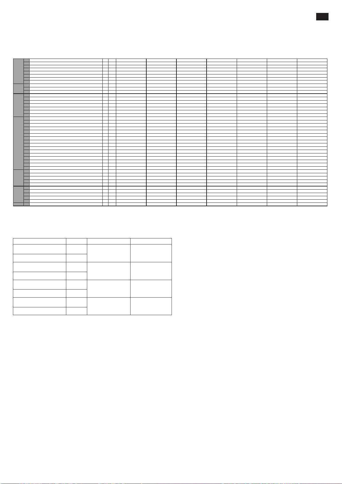
INHOUD (1.1)
1.1 CONSTRUCTEUR PR INDUSTRIAL PR INDUSTRIAL PR INDUSTRIAL PR INDUSTRIAL PR INDUSTRIAL PR INDUSTRIAL PR INDUSTRIAL
Q kg 1200 1200 1200 1200 1200 1200 1200
c mm 600 600 600 600 600 600 600
x mm 780 780 780 780 780 780 780
y mm 1234 1234 1234 1234 1234 1234 1234
kg 530 545 578 570 585 618 615
kg 543/1187 558/1187 591/1187 583/1187 598/1187 631/1187 628/1187
kg 368/162 383/162 416/162 408/162 423/162 456/162 453/162
b
10
mm 565 565 565 565 565 565 565
b
11
mm 410 410 410 410 410 410 410
h
1
mm 1787 1987 2250 1787 1987 2250 1965
h
2
mm - - 80 - - 80 1402
h
3
mm 2410 2810 3410 2410 2810 3410 2810
h
4
mm 2992 3392 3916 2992 3392 3916 3372
h
5
mm - - - - - - -
h
14
mm 915/1310 915/1310 915/1310 960/1330 960/1330 960/1330 960/1330
h
13
mm 90 90 90 90 90 90 90
l
1
mm 1760 1760 1760 1760 1760 1760 1760
l
2
mm 609 609 609 609 609 609 609
b
1
mm 800 800 800 800 800 800 800
s/e/l mm 70/150/1150 70/150/1150 70/150/1150 70/150/1150 70/150/1150 70/150/1150 70/150/1150
b
3
mm 650 650 650 650 650 650 650
b
5
mm 560 560 560 560 560 560 560
m
2
mm 20 20 20 20 20 20 20
A
st
mm 2210 2210 2210 2210 2210 2210 2210
W
a
mm 1430 1430 1430 1430 1430 1430 1430
km/h 4,7/5,2 4,7/5,2 4,7/5,2 4,7/5,2 4,7/5,2 4,7/5,2 4,7/5,2
m/s 0,11/0,19 0,11/0,19 0,11/0,19 0,11/0,19 0,11/0,19 0,11/0,19 0,10/0,18
m/s 0,12/0,15 0,12/0,15 0,12/0,15 0,19/0,19 0,19/0,19 0,19/0,19 0,16/0,14
% 5/10 5/10 5/10 5/10 5/10 5/10 5/10
kW 0,7 0,7 0,7 0,7 0,7 0,7 0,7
kW 2,2 2,2 2,2 2,2 2,2 2,2 2,2
V/Ah 24/85 (C20) 24/85 (C20) 24/85 (C20) 24/118 (C5) 24/118 (C5) 24/118 (C5) 24/118 (C5)
kg 38 38 38 78 78 78 78
kWh/h 0,9 0,9 0,9 0,9 0,9 0,9 0,9
dB(A) 62 62 62 62 62 62 62
G=Rubber, P=Polyurethaan, N=Nylon
GEWICH_T
TECHNISCHE GEGEVENS.............................................................BLZ. 25
VERKLARING VAN DE TRILEMISSIE.............................................BLZ. 25
GEBRUIK VAN DE MACHINE..........................................................BLZ. 25
BESCHRIJVING VAN DE WAGEN ..................................................BLZ. 25
VEILIGHEIDSMECHANISMEN........................................................BLZ. 25/26
PLAATJES........................................................................................BLZ. 26
VERVOER EN INGEBRUIKNAME...................................................BLZ. 26
ACCU ...............................................................................................BLZ. 26
GEBRUIK .........................................................................................BLZ. 26/27
ONDERHOUD..................................................................................BLZ. 27
IN GEVAL VAN PROBLEMEN..........................................................BLZ. 28
TECHNISCHE GEGEVENS (3.46)
1.2 MODEL GX 12/25 III ED. BASIC GX 12/29 III ED. BASIC GX 12/35 III ED. BASIC GX 12/25 III ED. EVO GX 12/29 III ED. EVO GX 12/35 III ED. EVO GX 12/29 III ED. FL EVO
1.3 AANDRIJVING ELEKTRISCH ELEKTRISCH ELEKTRISCH ELEKTRISCH ELEKTRISCH ELEKTRISCH ELEKTRISCH
1.4 BESTURINGSSYSTEEM BEGELEIDING BEGELEIDING BEGELEIDING BEGELEIDING BEGELEIDING BEGELEIDING BEGELEIDING
1.5 HEFVERMOGEN
1.6 ZWAARTEPUNT
BESCHRIJVING
1.8 ASAFSTAND LASTWIELEN VANAF VORKBASIS
1.9 WIELBASIS
2.1 GEWICHT TIJDENS WERKING MET BATTERIJ (zie lijn 6,5)
2.2 BELASTING OP ASSEN MET LAST, VOORAAN/ACHTERAAN
EN
2.3 BELASTING OP ASSEN ZONDER LAST, VOORAAN/ACHTERAAN
3.1 BANDEN * G+P/P G+P/P G+P/P G+P/P G+P/P G+P/P G+P/P
3.2 AFMETINGEN VOORWIELEN (Ø x breedte) 250x76 250x76 250x76 250x76 250x76 250x76 250x76
3.3 AFMETINGEN ACHTERWIELEN (Ø x breedte) 82x70 82x70 82x70 82x70 82x70 82x70 82x70
3.4 AFMETINGEN ZIJWIELEN (Ø x breedte) 100x38 100x38 100x38 100x38 100x38 100x38 100x38
3.5 AANTAL WIELEN (x=AANDRIJVING) VOORAAN/ACHTERAAN 1x+1/2 1x+1/2 1x+1/2 1x+1/2 1x+1/2 1x+1/2 1x+1/2
3.6 SPOORBREEDTE VOORAAN
FRAME/WIELENAFMETINGENPRESTATIES
3.7 SPOORBREEDTE ACHTERAAN
4.2 HOOGTE, GESLOTEN MAST
4.3 VRIJE HEFFING
4.4 HEFHOOGTE
4.5 HOOGTE, UITGESCHOVEN MAST
4.6 AANVANKELIJKE HEFFING
4.9 HOOGTE DISSELBOOM IN RIJPOSITIE MIN/MAX
4.15 HOOGTE VORKEN LAAG GEPLAATST
4.19 TOTALE LENGTE
4.20 LENGTE AANDRIJFUNIT
4.21 TOTALE BREEDTE
4.22 AFMETINGEN VORKEN
4.24 FRONTALE BREEDTE VORKEN
4.25 BREEDTE VORKEN
4.32 VRIJE RUIMTE OP DE HELFT VAN DE WIELBASIS
4.34 GANGPAD VOOR PALLET 800x1200 OVERLANGS
4.35 DRAAICIRKEL
5.1 RIJSNELHEID, MET/ZONDER LAST
5.2 HEFSNELHEID, MET/ZONDER LAST
5.3 DALINGSSNELHEID, MET/ZONDER LAST
5.8 TE OVERSCHRIJDBARE HELLING, MET/ZONDER LAST
5.10 DIENSTREM ELEKTRISCH ELEKTRISCH ELEKTRISCH ELEKTRISCH ELEKTRISCH ELEKTRISCH ELEKTRISCH
6.1 VERMOGEN TRACTIEMOTOR
6.2 VERMOGEN HEFMOTOR
6.4 SPANNING BATTERIJ, NOMINALE CAPACITEIT
6.5 GEWICHT BATTERIJ
MOTOREN
ELEKTRISCHE
6.6 ENERGIEVERBRUIK VOLGENS CICLUS VDI
8.4 LAWAAIERIGHEID VOOR DE BEDIENER
NL
VERKLARING VAN DE TRILEMISSIE (33.2)
De waarden van de trilemissie worden verklaard conform EN 12096
TestoppervlakBeschrijving Waarde Europese norm (EN)
Gemeten waarde van de
trilemissie, a (m/s
2
)
Onnauwkeurigheid, K (m/s
Gemeten waarde van de
trilemissie, a (m/s
2
)
Onnauwkeurigheid, K (m/s
Gemeten waarde van de
trilemissie, a (m/s2)
Onnauwkeurigheid, K (m/s
Gemeten waarde van de
trilemissie, a (m/s
2
)
Onnauwkeurigheid, K (m/s
0.71
2
)
0.68
2.3
2
)
0.6
0.77
2
)
0.39
1.02
2
)
0.08
EN ISO 20643
(Hand-Arm)
EN ISO 20643
(Hand-Arm)
EN 13059
(Volledig lichaam)
EN 13059
(Volledig lichaam)
Ondergrond in
gladde industrile
cement
Op testpiste
volgens EN 13059
Ondergrond in
gladde industrile
cement
Op testpiste
volgens EN 13059
De waarden zijn bepaald overeenkomstig EN ISO 20643 en EN 13059.
GEBRUIK VAN DE MACHINE(4.1)
Deze machine is ontworpen voor het opheffen en het vervoer van ladingen op gladde vloeren. Op de chassis bevindt zich een identificatieplaatje met daarop het opheffingsvermogen dat in geen geval
overschreden mag worden voor de veiligheid van het personeel en om het voertuig niet te beschadigen. Wij raden u aan de veiligheidsnormen en de normen betreffende het gebruik en het onderhoud
zeer strikt te respecteren. Het monteren van bijgevoegde onderdelen aan het apparaat moet vooraf door het CONSTRUCTIEBEDRIJF goedgekeurd worden.
BESCHRIJVING VAN DE PALLETTRUCK (5.16) (zie fig. 1)
Deze truck is een elektrische heftruck met vorken en stuurstang, ideaal voor het bergen en vervoeren van ladingen over vlakke en gladde oppervlakten. Het stuurmechanisme is goed zichtbaar en
eenvoudig te bedienen. De pallettruck is conform aan alle huidige E.G. veiligheidsvoorschriften.
De tekening laat de belangrijkste onderdelen zien:
1) STUURSTANG 2) AANDRIJFWIEL 3) HYDRAULISCHE EENHEID 4) HULPONTGENDELING VORK 5) HEFVORK 6) TWEEDE FASE 7) CHASSIS 8) OPHEFCILINDER
9) HOOFDSCHAKELAAR 10) ELEKTRONISCHE KAART CONTROLE VORK (EVO) 11) ELEKTRONISCHE KAART 12) STABILISATOREN 13) CARTER 14) PARACHUTEKLEP 15) ACCU
16) ELEKTRISCHE REM 17) LAADROLLEN 18) HANDBESCHERMING 19) GELIJKRICHTER 20) HEFCILINDER VORK (enkel versie Free Lift) 21) HEFCILINDER TWEEDE STEIGER (enkel
versie Free Lift)
VEILIGHEIDSMECHANISMEN (6.12) (zie fig. 1)
1) HOOFDSCHAKELAAR (ref.9) 2) ELEKTROREM (ref.16) 3) VENTIEL VOOR STROOMBEPERKING (ref. 14) 4) MAXIMALE DRUK VENTIEL 5) BUMPER BESCHERMING: deze zorgt voor de bescherming van
het aandrijfwiel (ref.2), de stabilisatoren aan de zijkant (ref.12) en de laadrollen aan de voorkant (ref.17); in geval van een ongeluk zijn de voeten en de lading dus beschermd. 6) "DODE MAN" MECHANISME (ref.2/fig.3):
het gaat hier om een veiligheidsschakelaar op het stuur die de bestuurder beschermt tegen een botsing bij het achteruit rijden. 7) HANDBESCHERMING (ref.18) 8) HULPONTGENDELING VORK (ref.4)
Structuur(7.10)
Het hefgedeelte met de benen en de motorkap vormen een onbuigzaam geheel (REF.7). De vorken worden met precisie geleid door 4 rollen die over de hele lengte van het hefgedeelte lopen.
Het aandrijfwiel, een draaiende wielen en twee rollen verlenen de truck zeer veel stabiliteit op 4 steunpunten.
De carters (ref.13) zijn eenvoudig te openen zodat alle gedeeltes goed bereikbaar zijn voor de klantendienst.
Tractie (8.4)
De aandrijfeenheid drijft het aandrijfwiel middels kegel- en cilindervormige raderwerk aan. Men kan van richting veranderen door de smoorkleppen op de stuurstang (ref.1/fig.3) te bewegen.
Stuurstang (9.12) (ref.1/fig.1)
De heftruck kan lopend worden bestuurd. De stuuruitslag bedraagt 210°. De disselboom werkt direct op het aandrijfwiel dus om van richting te veranderen moet men hem in de gewenste richting
draaien. Om de heftruck te bedienen (zie fig.2) moet men de disselboom in de middelste stand houden (pos.B), en om hem te stoppen moet men hem in de bovenste (pos.A) of in de onderste stand
houden (pos.C). Na loslaten van de disselboom komt deze automatisch in de bovenste stand terug (pos.A) en fungeert als parkeerrem. In de modaliteit “schildpad”, wanneer de disselboom zich in de
bovenste positie bevindt (pos.A) of in de onderste (pos.C), druk op de toets van de toets “schildpad” (ref.8, fig.3) en bedien de snelheidsregelaar (ref.1, fig.3) om de wagen op lage snelheid te
verplaatsen.
25

Remmen(10.7)
De bedrijfsrem wordt door de motor in werking gesteld als de gashendel wordt losgelaten. De elektromagnetische rem werkt als parkeer- en noodrem. De noodrem wordt in werking gesteld door de
dissel in de bovenste stand (stand A) of in de onderste stand (stand C) (zie afb. 2) te zetten. Als het elektrische systeem wordt uitgeschakeld, werkt de elektromagnetische rem als parkeerrem.
Hydraulisch circuit (11.11)
Om de vorken verticaal te bewegen bedient men eenvoudig de knoppen van de stuurstang (ref.4,5/fig.3) opdat de motorpompeenheid (ref.3/fig.1) de hydraulische olie van
de tank naar de hefcilinder vervoert. De hiervoor benodigde energie wordt geleverd door de accu (ref.15/fig.1).
In geval van een defect van het elektrische systeem, of wanneer geen energie meer aanwezig is in de accu, wanneer de vorken hoog zijn gesteld, kan de daling uitgevoerd
worden door te handelen op het handmatige deblokkeersysteem (REF.4/AFB.1) dat is geïnstalleerd op de elektromagnetische klep.
Er zijn twee veiligheidsventielen geïnstalleerd in het hydraulische circuit:
Blokkeerlep, zorgt dat de lading niet plotseling valt indien het hydraulische systeem kapot gaat. Bevindt zich in de hefcilinder.
Maximale druk ventiel, bevindt zich in de motorpomp en beschermt het mechanische en hydraulische systeem tegen overbelasting.
Elektrisch circuit(12.9)
Het elektrische circuit is gebouwd volgens de geldende normen en bestaat uit een te programmeren, elektronische variometer (ref.11/fig.1) (voorzien van alle regelingen
en veiligheden) en de stuurorganen die bedient kunnen worden vanaf de bovenkant van de stuurstang.
De aansluitingen zijn verzekerd tegen toevallige verslapping. De conductoren zijn van koper en zeer buigzaam en hebben de juiste doorsnede voor de gebruiksomstandigheden
en eventuele invloeden van buitenaf. Alle elektrische onderdelen zijn zo gemonteerd dat een goed gebruik en een eenvoudig onderhoud gewaarborgd zijn.
PLAATJES (13.13) (zie fig.4)
Op de machine zijn de volgende plaatjes zichtbaar: A) Identificatieplaatje van het type voertuig B) Accuplaatje C) Plaatje met ladingsdiagram betreffende de hefhoogte en positie van het zwaartepunt
van de lading op de vork D) Plaatjes met kabelpunten E) Plaatjes die aangeven dat het gevaar bestaat de voeten te vermorzelen F) Plaatjes met gebruiksverbod G) Plaatje lees instructies
H) Opschrift beschikken waaruit ongeveer de hoogte waarop de voorvork wordt opgeworpen I) Plaatje drukknop “schildpad”
De plaatjes mogen absoluut niet weggehaald of onleesbaar gemaakt worden.
BELANGRIJK: HET IS VERBODEN DE OP PLAATJE TYPE C AANGEGEVEN DRAAGKRACHT TE OVERSCHRIJDEN. DIT PLAATJE WORDT BIJ DE VERKOOP OP HET APPARAAT
AANGEBRACHT EN ZIET ER ALS VOLGT UIT:
Dit diagram laat de verhouding zien tussen de maximaal op te heffen lading en de betreffende maximale hoogte vanaf de grond bij het laden en lossen van een pallet van een rek.
Het hiernaast aangegeven schema van de vork geeft de positie van het zwaartepunt van de lading aan. De lading moet zo gelijkmatig mogelijk over de gehele lengte van de vork verdeeld
worden.
VERVOER EN INBEDRIJFSTELLING
Vervoer (14.10)
Om de pallettruck te vervoeren zijn er twee kabelpunten aangegeven zoals op de plaatjes "D" (fig.4), terwijl het gewicht van de machine aangegeven staat op het identificatieplaatje "A"(fig.4).
Voordat wordt vastgesnoerd, wordt aanbevolen om de handbescherming bovenaan (Ref.18, afb.1) te verwijderen om te vermijden dat ze kan breken. Monteer deze bescherming opnieuw voordat de
machine in werking wordt gesteld.
Het verdient aanbeveling de heftruck tijdens het transport stevig te bevestigen zodat hij niet kan kantelen. Controleer of er uit accu (idien aanwezig) geen zuur of dampen vrijkomen.
Inbedrijfstelling(15.1)
Voordat de machine in gebruik genomen wordt dient men te controleren of alle delen in perfecte conditie verkeren. Tevens dient men het functioneren van alle eenheden en de volledigheid van de
veiligheidsmechanismen te controleren. De pallettruck verplaatsen met de stroom van de accu en nooit met de rechtgezette wisselstroom, dit om de elektrische onderdelen niet te beschadigen.
ACCU (16.7)
Aanwijzingen, veiligheidsnormen en onderhoud
De inspectie, het opladen en het wisselen van de accu moet door bevoegd personeel uitgevoerd worden volgens de gebruiksaanwijzingen van het constructiebedrijf. Het is verboden te roken en
ontvlambaar materiaal of materiaal dat vonken afgeeft dichtbij de pallettruck en het oplaad-apparaat te houden. De ruimte dient goed gelucht te worden. Voor een goed onderhoud dienen de doppen
van de elementen geheel droog en schoon te zijn. Het vrijgekomen zuur verwijderen en een beetje vaseline op de klemmen smeren en dichtknijpen. Het gewicht en de afmetingen van de accu kunnen
invloed uitoefenen op de stabiliteit van de pallettruck en indien er een andere accu dan de standaard accu gemonteerd wordt raden wij aan het constructiebedrijf te interpelleren voor de nodige
toestemming.
De wagen heeft een indicator van de status van de accu die oplicht wanneer de machine wordt ingeschakeld. In geval van inactiviteit van de machine wordt deze automatisch uitgeschakeld; ze licht
opnieuw op wanneer de machine wordt ingeschakeld. De groene led duidt aan dat de accu’s voldoende opgeladen zijn. Wanneer het laadniveau onvoldoende begint te worden, licht het oranje licht
op; er kunnen nog enkele werkcycli uitgevoerd worden. Wanneer de restlading een niveau van minder dan 20% bereikt, gaat het rode licht branden. In deze conditie kan geen last meer opgetild worden,
maar kan de machine nog bewegen om het stopcontact voor het opladen te bereiken. De indicator wordt ook geactiveerd gedurende de fase van het opladen, om het verloop aan te duiden.
Acculading
Controleer, alvorens de accu op te laden, of de kabels intact zijn. Sluit de stekker van de batterijlader (A) aan op het stroomnet (zie afb.3). Als de machine is opgeladen, wordt de stroomtoevoer
onderbroken en licht de groene led op. Koppel de stekker (A) los van het stroomnet. Een normale oplaadcyclus duurt van 10 tot 12 uren. Er wordt aanbevolen om de batterij op te laden na de gebruiksuren
van de machine.
De acculader is zo ontworpen dat hij een standby-lading garandeert gedurende een bepaalde tijd nadat de accu volledig is opgeladen. Er bestaat geen risico van overbelasting en dus is het niet
noodzakelijk de acculader af te koppelen nadat de accu volledig is opgeladen.
De accu nooit geheel ontladen en incomplete oplading vermijden; verder steeds de accuoplader het einde van het opladen aan laten geven. Let op: indien de accu te veel ontladen wordt
gaat hij korter mee.
Vervanging van de accu (17.4)
a) Verwijder de achterkap b) de kabels van de accupolen losmaken c) de accu aan de zijkant uittrekken d) Voer de procedure in omgekeerde volgorde uit om de accu weer in zijn zitting te monteren
(Steeds hetzelfde accutype als de oorspronkelijke accu gebruiken)
BELANGRIJK: VOORZICHTIG OMGAAN MET HET ZWAVELZUUR, HET IS EEN GIFTIGE EN BIJTENDE STOF; KLEEFT AAN DE HUID EN AAN KLEDING DIE DAN MET VEEL WATER EN ZEEP
GEWASSEN DIENEN TE WORDEN. BIJ ONGEVAL METEEN EEN ARTS WAARSCHUWEN!!!
Indien de accu wordt vervangen, moet de oude ingezameld worden en naar het dichtst bijzijnde inzamelcentrum gebracht worden.
Accu controle
De gebruiks- en onderhoudsaanwijzingen van het constructiebedrijf van de accu aandachtig doorlezen. Zorg ervoor dat er geen corrosie aanwezig is, dat er vaseline op de klemmen zit en dat het zuur
15 mm boven de plaatjes staat. Indien de elementen niet bedekt zijn opvullen met gedestilleerd water. De dichtheid van de elektrolyten met een dichtheidsmeter meten om zo het niveau van de lading
te controleren.
GEBRUIK (18.17)
De bestuurder dient de volgende gebruiksaanwijzingen in de rijpositie uit te voeren; de handelingen dienen zo uitgevoerd te worden dat men redelijk ver van de gevaarlijke zones (hefmasten, vork, kettingen,
poelies, aandrijfwielen en stabilisatoren en andere in beweging zijnde onderdelen) blijft i.v.m. de veiligheid van de handen en voeten.
Veiligheidsnormen
De pallettruck dient volgens de volgende normen gebruikt te worden:
De bestuurder van de machine moet opgeleid zijn, moet de gebruiksinstructies van het voertuig kennen, en moet geschikte kleding en een helm dragen.
De elektronische pallettruck mag alleen gebruikt worden door personen boven de 18 jaar die hiervoor professioneel opgeleid zijn.
De bestuurder is verantwoordelijk voor de pallettruck en dient er voor te zorgen dat onbevoegde personen niet met de truck rijden of op de vork klimmen.
Tijdens het rijden dient de gebruiker snelheid te verminderen in de bochten, bij smalle stukken, deuren of onregelmatige vloeren. De gebruiker dient onbevoegden te verwijderen uit de zone waarin de pallettruck
zich beweegt en onmiddellijk te waarschuwen indien er personen in gevaar zijn; in het geval er, ondanks de waarschuwing, nog steeds personen op de werkplek zijn dient de bestuurder de pallettruck meteen
te stoppen.
Het is verboden te blijven staan in de zones waar er onderdelen in beweging zijn en te klimmen op de vaste delen van de pallettruck.
De bestuurder dient plotseling afremmen en snelle richtingsveranderingen te vermijden.
Ingeval van omhoog of omlaaggaande stukken, met max. toegestane helling, dient de bestuurder de lading hoog te houden en snelheid te verminderen.
Tijdens het rijden dient de bestuurder er op te letten dat er een goede zichtbaarheid is en dat er voldoende ruimte is bij het achteruit rijden.
indien de pallettruck met de lift vervoerd wordt, dient de pallettruck hier met de vork naar voren in te rijden (eerst controleren dat de lift voldoende draagkracht heeft).
Het is ten strengste verboden de veiligheidsmechanismen buiten bedrijf te stellen of te demonteren. Indien de pallettruck in een omgeving met hoog brand- en explosiegevaar ingezet wordt, moet de pallettruck
hiervoor goedgekeurd zijn.
De MAXIMALE DRAAGKRACHT van de pallettruck zoals aangegeven op plaatje "A" (fig.4) mag in geen geval overschreden worden. De bestuurder dient zich ervan te verzekeren dat de lading goed en ordelijk
op de vork verdeeld staat. De lading mag in geen geval meer dan 50 mm van de vork uitsteken.
Voordat er met het werken begonnen wordt dient de bestuurder eerst het volgende te controleren:
- de werking van de rem en de parkeerrem
- dat de ladingsvorken in perfecte conditie verkeren
- dat de wielen en rollen heel zijn
- dat de accu opgeladen is en goed vast zit en dat de elementen droog en schoon zijn
- dat alle veiligheidsmechanismen goed werken
Het gebruik van de palletruck onderbreken indien de toestand van de accu ongeveer 20 % van de beschikbare lading aangeeft en dan de accu opladen.
De pallettruck mag niet gebruikt of geparkeerd worden in de regen of sneeuw, of in zeer vochtige zones.
Gebruikstemperatuur: -10°, +40°.
Vermijd het gebruik van de heftruck om andere voertuigen of heftrucks voort te slepen.
Eventuele schade, defecten en storingen moeten onmiddellijk gemeld worden aan de verantwoordelijke. De heftruck mag niet gebruikt worden tot de herstelling is uitgevoerd.
Indien de bestuurder niet in het bezit is van de noodzakelijke kwalificatie, mag hij geen herstellingen aan de heftruck uitvoeren, en mag hij de veiligheidsinrichtingen en de schakelaars niet deactiveren of
wijzigen.
26
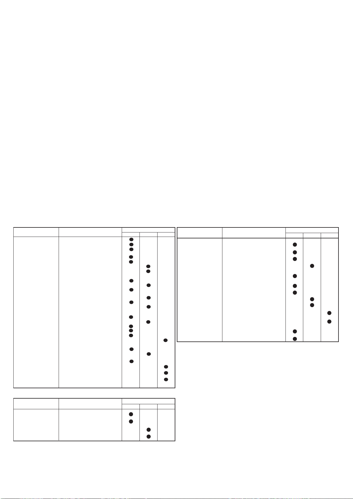
IN GEVAL VAN SCHADE OF ONGEVAL WEGENS NALATIGHEID, MONTAGE DOOR NIET BEVOEGDE TECHNICI EN ONJUIST GEBRUIK KAN HET CONSTRUCTIEBEDRIJF NIET
VERANTWOORDELIJK GESTELD WORDEN.
Vervoeren
Voordat men de pallettruck gebruikt, eerst controleren of de claxon en de rem werken en of de accu geheel opgeladen is. De sleutel naar positie 1 draaien en de stuurstang naar de rijpositie brengen.
De regelaar langzaam draaien en zich naar de gewenste werkplek bewegen. Om te remmen of volkomen stil te staan, de regelaar in de tegengestelde richting draaien. De pallettruck steeds voorzichtig
besturen aangezien plotselinge bewegingen gevaarlijke situaties voortbrengen (des te meer wanneer de pallettruck een hoge snelheid heeft). Altijd met de vork in de lage positie rijden en snelheid
verminderen in smalle stukken en in de bochten.
Stapelen
1) Voorzichtig naar het rek rijden met de lading in de lage positie. 2) controleren of de benen van de pallettruck een vrije ruimte hebben onder de pallet of in het rek. Het beste is de zijkant van de op
te heffen pallet in gelijke lijn te brengen met de laatste in het rek als uitgangspunt. Op deze manier zal het stapelen en lossen eenvoudiger zijn. 3) De lading opheffen zodat deze boven het stapelvlak
komt. 4) Langzaam naar voren bewegen en stoppen wanneer de lading boven het rek is; nu de vork naar beneden laten zodat de pallet vrij komt en zodat er geen druk op de onderliggende plank
wordt uitgeoefend. Controleren of de lading veilig geplaatst is. 5) Langzaam naar achteren bewegen terwijl men er op let dat de pallet goed gestapeld blijft liggen. 6) De vork naar beneden brengen,
in de rijpositie (FIG.6).
Lossen
1) Met de vork in de loodrechte, lage positie naar het rek toe rijden en onder de laagste pallet rijden. 2) De vork onder de pallet vandaan terugtrekken. 3) De vork naar de gewenste hoogte brengen
en langzaam naar de op te nemen pallet bewegen. Gelijktijdig er op letten dat de lading veilig op de vork geplaatst wordt. 4) De vork opheffen totdat de pallet van het rek opgeheven wordt.
5) Langzaam naar achteren bewegen 6) De lading langzaam laten zakken en gelijktijdig opletten dat de vork geen hindernissen tegenkomt tijdens het zakken.
Gebruiksmodaliteit aan beperkte snelheid (“kruipsnelheid”)
Voor het gebruik in nauwe ruimtes, of om delicate goederen precies en veilig te verplaatsen, kan de gebruiksmodaliteit “kruipsnelheid” ingesteld worden. De modaliteit van de kruipsnelheid kan enkel
gebruikt worden als de disselboom helemaal hoog is gesteld. Voor de handelingen in de modaliteit van de kruipsnelheid moet de toets (ref.8/afb.3), met afbeelding van een schildpad, ingedrukt gehouden
worden en moet op de bedieningen gehandeld worden voor de verplaatsing en de beweging van de vorken, zoals voor de handelingen in de standaard modaliteit.
LET OP: Altijd het gewicht van de lading vergelijken met de ophefcapaciteit zoals aangegeven op het desbetreffende plaatje.
LET OP: Wanneer de lading opgeheven is dient men zeer voorzichtig te sturen en te remmen.
Hefblokkering (28.2)
De heftruck is voorzien van een automatische inrichting die het heffen blokkeert als de accu’s een ontladingsniveau
bereiken van meer dan 80%. De ingreep van het systeem wordt gemeld door de rode led van de indicator van de staat van de batterij.
STUURINSTRUMENTEN (19.13) (fig. 3)
1) Versnelling; 2) “dode man” toets; 3) Toets akoestische melder; 4) Heftoets; 5) Daaltoets; 6) Hoofdschakelaar; 7) Waarschuwingslicht accu 8) Knop "schildpad" (lage snelheid)
9) Waarschuwingslicht accu en urenteller
ONDERHOUD (20.6)
Het onderhoud dient uitgevoerd te worden door bevoegd personeel. De pallettruck dient minstens een maal per jaar een algemene controle te ondergaan. Na iedere onderhoudsbeurt dienen de werking
van de pallettruck en de veiligheidsmechanismen gecontroleerd te worden. De pallettruck regelmatig laten controleren, uit veiligheidsoverwegingen ten opzichte van het personeel en om het risico te
vermijden dat de wagen stil komt te staan ! (zie onderhoudstabel)
Opmerking: Om het onderhoud in veilige omstandigheden uit te voeren dient men de stekker van de hoofdschakelaar er uit te halen.
Onderhoudstabel
ELEMENT CONTROLE
STRUCTUUR EN VORK Controle draagelementen
REMMEN
WIELEN Controle slijtage
STUURSTANG
ELEKTRISCH SYSTEEM
HYDRAULISCH SYSTEEM
Controle schroeven en bouten
Controle aanslagen en speling
vork
Controle werking
Controle slijtage remschoen
Controle remkracht
Controle speling (circa 0,4
mm)
Controle speling lagers
Controle verankering
Controle speling
Controle zijwaartse beweging
Controle terugkeer in verticale positie
Controle slijtage contact mechanisme
Controle aansluitingen, schade aan de kabels
Controle hoofdschakelaar
Controle claxon
Controle "dode man" toets
Controle waarde zekeringen
Controle werking
Controle olieniveau
Controle slijtage en lekken van de aansluitingen
Olie/filter wisselen
Controle werking druk-afnameventiel
Controle ventiel voor
stroombeperking
Smeermiddelen tabel
DE IN TE SMEREN
DELEN
WIELEN EN ROLLENILithiumvet NLGI-2
HEFKETTING
MASTLEIDINGEN Lithiumvet NLGI-2
HYDRAULISCHE EENHEID
Lithiumvet NLGI-2
Olie
TYPE
SMEERMIDDEL
ISO VG 32
LGI-2
3 maanden 6 maanden 12 maanden
ELKE
ELKE
ELEMENT CONTROLE
CILINDER
ELEKTROMOTOREN
ACCU
INSPECTIES
Afstelling hoogte aandrijfwiel (Afb. 5)
Regel de hoogte van het aandrijfwiel om slijtage te compenseren, door de volgende
procedure te volgen:
1) Demonteer de onderste carter;
2) Plaats, met de disselboom in positie “0”, een schroevendraaier in de opening
van de afstandhouder ref.1 en draai de disselboom in de richting “A” (1/4 draai
= 0,5 mm uittrekking van het aandrijfwiel);
3) Verwijder de schroevendraaier en draai de disselboom in de richting “B” tot
positie “0” opnieuw wordt bereikt;
4) Herhaal de handelingen van punt 2 en 3 zo vaak als nodig (indien het aandrijfwiel
teveel is uitgetrokken, moeten de handelingen 2 en 3 herhaald worden door in
de tegengestelde richting te draaien);
5) Draai de moer ref.2 vast tegen de afstandhouder Ref.1, en monteer de onderste
carter opnieuw.
N.B. Vervang het wiel voordat de dikte van het rijvlak dunner dan 5 mm is
Controle werking, lekkage en
slijtage van de pakkingen
Controle poelies
Controle slijtage borstels
Controle relais van motoraandrijving
Controle dichtheid en niveau elektrolyten
(niet nodig voor gel-accu’s)
Controle spanning van de elementen
Controle verankering en klemmen
Controle volledigheid van de kabels
Klemmen met vaseline invetten
Aardleiding van het elektrische circuit
controleren
Controle snelheid van vervoeren,
heffen en dalen van de ladingsvork.
Controle veiligheidsmechanismen
Hef- en daalproef met nominale lading
3 Maanden 6 Maanden 12 Maanden
ELKE
Altijd hydraulische olie gebruiken behalve motoren remolie.
Opmerking: zamel de gebruikte olie in door het milieu te respecteren. Er wordt
aanbevolen om de olie in vaten te gieten om deze vervolgens naar een inzamelcentrum
te brengen. De gebruikte olie in geen geval op de grond dumpen of achterlaten op
een ongeschikte plek.
HET SCHOONMAKEN VAN DE WAGEN: de onderdelen van de wagen, behalve de
elektrische en elektronische onderdelen, schoonmaken met een vochtige doek. Absoluut
niet wassen met directe waterstralen, stoom of ontvlambare vloeistoffen. De elektrische en
elektronische onderdelen schoonmaken met ontvochtigde, samengeperste lucht met een
lage druk (max. 5 bar) of met een niet-metalen borstel.
27
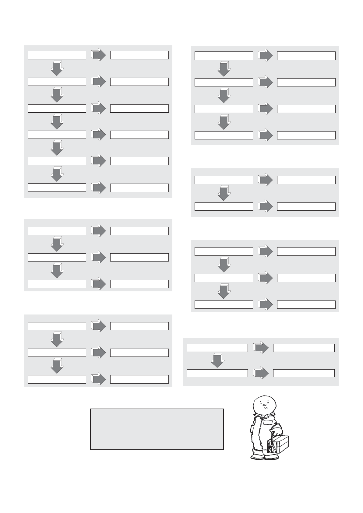
IN GEVAL VAN PROBLEMEN
DE MACHINE START NIET (21.2):
TIL DE HOOFDSCHAKELAAR OP ACCU OPLADEN
NEE
MICROSTUURSTANG KAPOT VERVANGEN
NEE
KRACHTZEKERING
DOORGEBRAND
NEE
HULPZEKERING DOORGEBRAND
NEE
SLEUTEL KAPOT MONTEREN NIEUWE SLEUTEL
NEE
KORTSLUITING ELEKTRISCH
CIRCUIT
JA
JA
JA
JA
VERVANGEN
VERVANGEN
JA
CONTROLEREN ELEKTRISCH
JA
CIRCUIT
DE VORK BLIJFT NIET OMHOOG (26.1):
DE VORK GAAT NIET OMHOOG (22.1):
VERLIES VAN OLIE IN HET
HYDRAULISCHE SYSTEEM
JA
NEE
OVERBELASTING
JA
NEE
ACCU LEEG ACCU OPLADEN
JA
NEE
GEEN OLIE IN DE TANK OLIE BIJVULLEN
JA
AANSLUITINGEN
CONTROLEREN
LADING VERMINDEREN
DE PALLETTRUCK REMT NIET (23.1):
LAAG REMKOPPEL
JA
NEE
REMSYSTEEM BESCHADIGD REM VERVANGEN
JA
REM OPNIEUW
INSTELLEN
VERLIES VAN OLIE IN
HETHYDRAULISCHE SYSTEEM
AANSLUITINGEN EN PAKKINGEN
JA
CONTROLEREN
NEE
DRUKVENTIEL VUIL VENTIEL SCHOONMAKEN
JA
NEE
PAKKINGEN VAN DE CILINDER
VERSLETEN
JA
PAKKINGEN WISSELEN
DE MOTORPOMP START NIET (24.1):
MOTORBORSTELS
VERSLETEN
NEE
STARTKNOP KAPOT VERVANGEN
NEE
ELEKTRISCHE AANSLUITINGEN
DEFEK
JA
JA
JA
VERVANGEN
AANSLUITINGEN NAKIJKEN
DE ACCU WORDT NIET OPGELADEN (25.1):
DE ACCU-OPLADER IS NIET
JUIST AANGESLOTEN
NEE
ZEKERING ACCU-OPLADER KAPOT
NEE
DEFECTE ZEKERING IN HOOFDNET
AANDRIJFWIEL SLIPT (34.2):
HOOGTE AANDRIJFWIEL
NIET CORRECT
NO
AANDRIJFWIEL VERSLETEN
JA
JA
JA
SI
SI
AANSLUITINGEN NAKIJKEN
VERVANGEN
VERVANGEN
AFSTELLING UITVOEREN
RING AANDRIJFWIEL VERVANGEN
LET OP !!!
INDIEN GEEN VAN DEZE OPLOSSINGEN HET
PROBLEEM OPLOST, DAN DE PALLETTRUCK
NAAR DE DICHTSTBIJZIJNDE
KLANTENSERVICE BRENGEN.
28
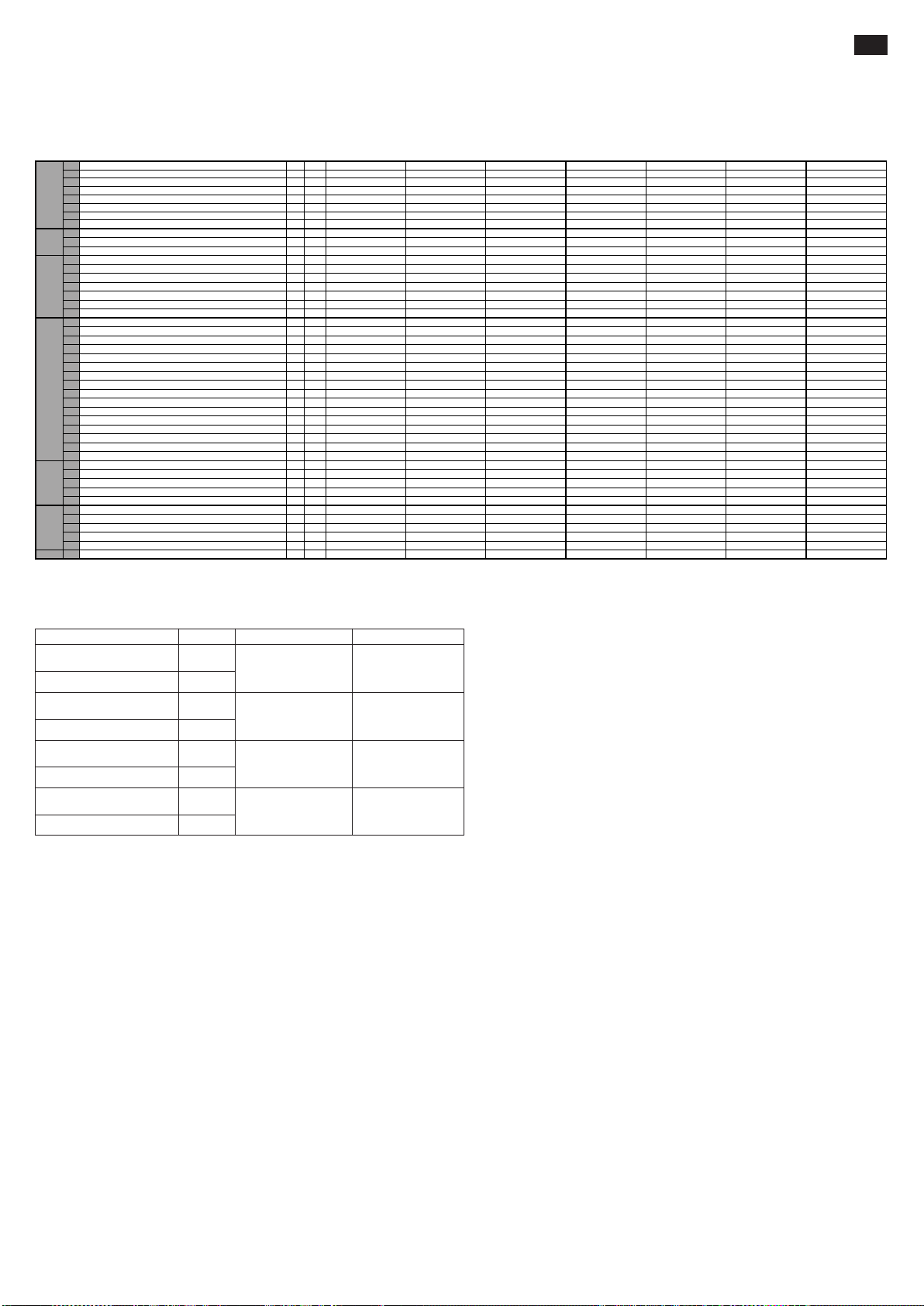
INDHOLD (1.1)
1.1 FABRIKANT PR INDUSTRIAL PR INDUSTRIAL PR INDUSTRIAL PR INDUSTRIAL PR INDUSTRIAL PR INDUSTRIAL PR INDUSTRIAL
Q kg 1200 1200 1200 1200 1200 1200 1200
c mm 600 600 600 600 600 600 600
x mm 780 780 780 780 780 780 780
y mm 1234 1234 1234 1234 1234 1234 1234
kg 530 545 578 570 585 618 615
kg 543/1187 558/1187 591/1187 583/1187 598/1187 631/1187 628/1187
kg 368/162 383/162 416/162 408/162 423/162 456/162 453/162
b
10
mm 565 565 565 565 565 565 565
b
11
mm 410 410 410 410 410 410 410
h
1
mm 1787 1987 2250 1787 1987 2250 1965
h
2
mm - - 80 - - 80 1402
h
3
mm 2410 2810 3410 2410 2810 3410 2810
h
4
mm 2992 3392 3916 2992 3392 3916 3372
h
5
mm - - - - - - -
h
14
mm 915/1310 915/1310 915/1310 960/1330 960/1330 960/1330 960/1330
h
13
mm 90 90 90 90 90 90 90
l
1
mm 1760 1760 1760 1760 1760 1760 1760
l
2
mm 609 609 609 609 609 609 609
b
1
mm 800 800 800 800 800 800 800
s/e/l mm 70/150/1150 70/150/1150 70/150/1150 70/150/1150 70/150/1150 70/150/1150 70/150/1150
b
3
mm 650 650 650 650 650 650 650
b
5
mm 560 560 560 560 560 560 560
m
2
mm 20 20 20 20 20 20 20
A
st
mm 2210 2210 2210 2210 2210 2210 2210
W
a
mm 1430 1430 1430 1430 1430 1430 1430
km/h 4,7/5,2 4,7/5,2 4,7/5,2 4,7/5,2 4,7/5,2 4,7/5,2 4,7/5,2
m/s 0,11/0,19 0,11/0,19 0,11/0,19 0,11/0,19 0,11/0,19 0,11/0,19 0,10/0,18
m/s 0,12/0,15 0,12/0,15 0,12/0,15 0,19/0,19 0,19/0,19 0,19/0,19 0,16/0,14
% 5/10 5/10 5/10 5/10 5/10 5/10 5/10
kW 0,7 0,7 0,7 0,7 0,7 0,7 0,7
kW 2,2 2,2 2,2 2,2 2,2 2,2 2,2
V/Ah 24/85 (C20) 24/85 (C20) 24/85 (C20) 24/118 (C5) 24/118 (C5) 24/118 (C5) 24/118 (C5)
kg 38 38 38 78 78 78 78
kWh/h 0,9 0,9 0,9 0,9 0,9 0,9 0,9
dB(A) 62 62 62 62 62 62 62
G=Dæk, P=Polyuretan, N=Nylon
TEKNISKE DATA..............................................................................SIDE 29
VIBRATIONSBELASTNINGSERKLÆRING.....................................SIDE 29
BRUG AF MASKINEN......................................................................SIDE 29
BESKRIVELSE AF MASKINEN .......................................................SIDE 29
SIKKERHEDS-UDSTYR ..................................................................SIDE 29/30
MÆRKATER.....................................................................................SIDE 30
TRANSPORT OG OPSÆTNING .....................................................SIDE 30
BATTERIET......................................................................................SIDE 30
BRUGSANVISNING.........................................................................SIDE 30/31
VEDLIGEHOLDELSE.......................................................................SIDE 31
PROBLEMLØSNING........................................................................SIDE 32
TEKNISKE DATA (3.46)
1.2 MODEL GX 12/25 III ED. BASIC GX 12/29 III ED. BASIC GX 12/35 III ED. BASIC GX 12/25 III ED. EVO GX 12/29 III ED. EVO GX 12/35 III ED. EVO GX 12/29 III ED. FL EVO
1.3 FREMDRIFT ELEKTRISK ELEKTRISK ELEKTRISK ELEKTRISK ELEKTRISK ELEKTRISK ELEKTRISK
1.4 STYRESYSTEM ESKORT ESKORT ESKORT ESKORT ESKORT ESKORT ESKORT
1.5 KAPACITET
1.6 TYNGDEPUNKT
BESKRIVELSEVÆGTESTEL/HJULDIMENSIONERYDELSEREL-MOTORER
1.8 LASTHJULAKSENS AFSTAND FRA GAFFELBASE
1.9 TRIN
2.1 VÆGT I DRIFT MED BATTERI (jfr. linje 6,5)
2.2 AKSEBELASTNING MED LAST, FORAN/BAGPÅ
2.3 AKSEBELASTNING UDEN LAST, FORAN/BAGPÅ
3.1 DÆK * G+P/P G+P/P G+P/P G+P/P G+P/P G+P/P G+P/P
3.2 FORHJULSDIMENSIONER (Ø x bredde) 250x76 250x76 250x76 250x76 250x76 250x76 250x76
3.3 BAGHJULSDIMENSIONER (Ø x bredde) 82x70 82x70 82x70 82x70 82x70 82x70 82x70
3.4 SIDEHJULSDIMENSIONER (Ø x bredde) 100x38 100x38 100x38 100x38 100x38 100x38 100x38
3.5 ANTAL HJUL (x=TRÆK) FORAN/BAGPÅ 1x+1/2 1x+1/2 1x+1/2 1x+1/2 1x+1/2 1x+1/2 1x+1/2
3.6 BAGHJULSVIDDE
3.7 BAGHJULSVIDDE
4.2 HØJDE, LUKKET VANGE
4.3 FRIT LØFT
4.4 LØFTEHØJDE
4.5 HØJDE, UDTRUKKET VANGE
4.6 BEGYNDELSESLØFT
4.9 STYRESTANGENS HØJDE I KØREPOSITION MIN/MAX
4.15 HØJDE VED SÆNKEDE GAFLER
4.19 TOTALLÆNGDE
4.20 MOTORVOGNSLÆNGDE
4.21 TOTALBREDDE
4.22 GAFFELDIMENSION
4.24 FRONTAL GAFFELBREDDE
4.25 GAFFELBREDDE
4.32 FRIHØJDE (VED HALVT TRIN)
4.34 PLADSKRAV VED OPMAGASINERING AF PALLE PÅ 800x1200 PÅ LANGS
4.35 DREJERADIUS
5.1 TRANSLATIONSHASTIGHED, MED/UDEN LAST
5.2 LØFTEHASTIGHED, MED/UDEN LAST
5.3 SÆNKEHASTIGHED, MED/UDEN LAST
5.8 OVERKOMMELIG HÆLDNING, MED/UDEN LAST
5.10 HJÆLPBREMSE ELEKTRISK ELEKTRISK ELEKTRISK ELEKTRISK ELEKTRISK ELEKTRISK ELEKTRISK
6.1 TRÆKMOTOREFFEKT
6.2 LØFTEMOTOREFFEKT
6.4 BATTERISPÆNDING, NOMINEL KAPACITET
6.5 GEWICHT BATTERIJ
6.6 ENERGIFORBRUG I HENHOLD TIL CYKLUSSEN VDI
8.4 LAWAAIERIGHEID VOOR DE BEDIENER
DA
VIBRATIONSBELASTNINGSERKLÆRING (33.2)
Erklærede vibrationsbelastningsværdier i overensstemmelse med EF 12096 normen
Opmålt vibrationsbelastning
ved, a (m/s2)
Usikkerhed, K (m/s
Opmålt vibrationsbelastning
ved, a (m/s
Usikkerhed, K (m/s
Opmålt vibrationsbelastning
ved, a (m/s2)
Usikkerhed, K (m/s
Opmålt vibrationsbelastning
ved, a (m/s
Usikkerhed, K (m/s
2
)
2
)
2
)
2
)
2
)
2
)
Europæisk normen (EF)
0.71
0.68
2.3
0.6
0.77
0.39
1.02
0.08
EF ISO 20643
norm (Hånd-Arm)
EF ISO 20643
norm (Hånd-Arm)
EF 13059 norm
(Helkropsvibrationer)
EF 13059 norm
(Helkropsvibrationer)
PrøvearealBeskrivelse Værd
Gulv i glat industriel
cement
Prøvebane in henhold
til EF 13059 normen
Gulv i glat industriel
cement
Prøvebane in henhold
til EF 13059 normen
Værdierne er fastlagt i overensstemmelse med EF ISO 20643 og EF 13059 normerne.
BRUG AF MASKINEN (4.1)
Denne maskine er blevet udviklet for at transportere og løfte gods på fuldstændig jævne flader. Et identifikations-skilt findes på chassis of viser vægt kapaciteten som under ingen omstændigheder må
overskrides, både af hensyn til personlig sikkerhed of for ikke at skade maskinen. Vejledningerne for sikkerhed, brug of vedligeholdelse bør overholdes til punkt of prikke. Montage af ekstra udstyr på
maskinen skal først autoriseres af den konstruerende virksomhed. Denne gaffeltruck må aldrig bruges på ujævne flader, uanset hvor små.
BESKRIVELSE AF TRUCKEN (5.16) (se fig. 1)
Denne maskine er en elektrisk gaffeltruck med styrehåndtag og er yderst velegnet til stabling og transportering af gods på fuldstændig lige og jævne overflader. Styremekanismerne er nemme .at få
øje på og at bruge. Maskinen er i overensstemmelse med alle EF-sikkerheds- og -komfort-regulationer. Tegningen viser dens hovedspecifikationer.
1) STYREHÅNDTAG 2) MOTOR-HJUL 3) HYDRAULISK UDLØB 4) MANUEL UDLØSNING FORK 5) LØFTEGAFFEL 6) ANDEN FASE 7) CHASSIS 8) LØFTE-CYLINDER
9) HOVED-AFBRYDER 10) GAFFELKONTROLLENS ELEKTRONISKE KORT (EVO) 11) ELEKTRONISK KORT 12) STABILISATORHJUL 13) MOTORHJELME 14) FALDSIKRINGSVENTIL
15) BATTERI 16) ELEKTRISK BREMSE 17) STØTTEHJUL 18) HAND-BESKYTTER 19) OPRETNINGSMEKANISME 20) GAFLEN LØFTECYLINDER (kun på version Free Lift)
21) ANDET STADIES LØFTECYLINDER (kun på version Free Lift)
SIKKERHEDSUDSTYR (6.12) (se fig. 1)
1. HOVED-AFBRYDER (pkt. 8) 2. ELEK1RISK BREMSE(pkt. 14) 3. VENTIL TIL BEGRÆNSNING AF STRØM (pkt. 12) 4. OVERTRYKS-VENTIL 5. STØDFANGERE: Beskytter motor-hjulet (pkt.
2), de sideanbragte stabilisatorhjul (pkt.12) samt de forreste støttehjul, mod stød. I tilfælde af uheld er fødder og gods såledesbes ede. 6. "DØD MANDS"- afbryder (pkt. 2/fig.3): dette er en
sikkerheds¬kontakt anbragt på styrehåndtaget og beskytter føreren mod sammenstød når trucken køres baglæns. 7. HAND-BESKYTTER (pkt. 18) 8. MANUEL UDLØSNING FORK (PKT. 4)
Struktur (7.10)
Løftemasterne, benene og motorhjelmen danner en meget hård struktur (pkt. 7). Gaflerne er præcisions-styrede af fire valser, der går op ad hele masten.
Drivhjulet, a hjul og to valser sikrer trucken høj stabilitet på fire støttepunkter.
To let-åbenlige motorhjelme (pkt. 13) giver adgang til alle vedligeholdelses-dele.
Styring (8.4)
Den driv-enhed bevæger motor-hjulet ved hjælp af gearerne. Bevægelse kan omstilles ved at bruge ventilerne placeret på styre-roret. (ref.1/fig.3)
Styrehåndtaget (9.12) (pkt.1/fig.1)
Pallelæsseren kan styres af en fører til fods. Styrevinklen er på 210º.
Styrestangen indvirker direkte på drivhjulet, og skal således drejes i den ønskede retning ved behov for retningsskifte. Når pallelæsseren startes (se fig. 2) skal styrestangen stilles i midterpositionen
(pos. B), hvorimod denne stang skal stilles i positionen foroven (pos. A) eller forneden (pos. C), når pallelæsseren skal standses. Når styrestangen slippes, vender den automatisk tilbage til positionen
foroven (pos. A), og virker som parkeringsbremse.
Med modaliteten “skildpadde”, når styreapparatet er i øverste (pos.A) eller i nederste (pos.C) position, ved at trykke på “skildpadde” taste (ref.8, fig.3) og samtidigt at handle på hastighedsregulatoren
(ref.1, fig.3), vil lø’bfftevognen flytte sig med nedsat hastighed.
Bremser(10.7)
Driftsstandsning udføres af motoren, ved at slippe speederen. Den elektromagnetiske bremse fungerer som parkeringsbremse og nødbremse. Nødbremsning foretages ved at føre stangen i øverste
position (pos.A) eller nederste position (pos.C) (se fig.2). Hvis det elektriske system kobles fra, fungerer den elektromagnetiske bremse som parkeringsbremse.
29

Hydraulisk kredsløb (11.11)
For at løfte of sænke gaflerne, brug styre-rorets kontrol funktioner (ref. 4,5/fig. 1) så motor pumpen (ref.3./fig.1) sender hydraulisk olie fra tanken til løfte cylinderen. Den nødvendige energi kommer fra batteriet (ref.
15/fig.1).
I tilfælde af skade på det elektriske system, eller opbrug af den akkumulerede energi på batteriet, mens vognens gafler er løftede, kan disse sænkes ved at flytte vognen,
ved at indvirke på systemet til manuel ophævelse af blokeringen (REF.4/FIG.1), som er installeret på magnetventilen.
To sikkerheds ventiler er installeret i det hydrauliske kredsløb:
a) Faldskærmsventil som er anbragt i løftecylinder, stopper lasten fra pludseligt at falde i tilfælde af at det hydrauliske kredsløb fejler.
b) Maksimum tryk ventilen - denne er anbragt if motor pumpen of beskytter det mekaniske of hydrauliske system fra overbelastning.
Elektrisk kredsløb (12.9)
Er konstrueret efter up-til-date regler of indluderer variabelt el-program (ref.11/fig.1) (leveret med sikkerheds of justerings udstyr), samt kontrol udstyr som fungerer
fra styre-roret. Forbindelserne er garanteret imod tilfældig slapning. Kobber-lederne er yderst fleksible of har en diameter som gør det muligt at operere under
mange forskellige forhold. Alle de elektriske komponenter er påbygget for at garantere brug of for at forenkle vedligeholdelse.
MÆRKATER (13.13) (se fig. 4)
Følgende mærkater forefindes på maskinen:
A) Mærkat til at identificere køretøjs-typen B) Batteri-mærkat C) Mærkat med lastnings-diagram refererende til løfte-højden og tyngdepunktet af gaflernes gods'
position. D) Mærkater, der indikerer, at fødder kan komme i klemme. E) Mærkater, der indikerer fastgørelses-punkter. F) Forbuds-mærkater G) Skilt, læs
vejledning H) Skildpadde" trykknap skilt. I) Advarsels-mærkat J) Skildpadde" trykknap skilt.
Mærkaterne må under ingen omstændigheder fjernes eller gøre ulæselige.
VIGTIGT: DET ER FORBUDT AT OVERSKRIDE VÆGTEN VIST PA MÆRKATEN C, DER ER FASTGJORT TIL MASKINEN I SALGS-ØJEBLIKKET, OG VIST
HER VED SIDEN AF: Diagrammet viser forholdet mellem den maksimalt loftelige vægt og den relative maksimums-højde over jorden under læsnings- og aflæsnings-manøvrer af en palle
fra en hylde. Diagrammet viser tyngdepunktet af godset, der, under alle omstændigheder, må fordeles så uniformt som muligt på hele gaflens længde.
TRANSPORT OG OPSÆTNING
Transport (14.10)
Benyt fastgørelses-punkterne som indikeret på mærkaterne "D" (fig. 4) for at transportere trucken. Maskinens vægt er indikeret på identifikations-mærkaten "A" (fig. 4).
Det anbefales at fjerne den øvre beskyttelse (Ref. 18, fig. 1), så den ikke tager skade. Montér beskyttelsen igen, inden maskinen sættes i funktion.
Det er en god regel, at sikre trucken under transport, så denne ikke kan vælte. Kontrollér, at der ikke løber syre dampe ud fra batteriet (hvis monteret).
Opsætning (15.1)
Før maskinen tages i brug, bør man sikre sig, at alle dens dele, deriblandt sikkerheds-installationerne, er i perfekt stand og funktionsdygtige. For at bevæge trucken skal der bruges batteri-strøm og
aldrig ensrettet vekselstrøm, da dette vil skade de elektriske komponenter.
BATTERIET (16.7)
Intruktion, sikkerheds-foranstaltninger samt vedligeholdelse
Inspektion, genopladning og udskiftning af batteri skal udføres af autoriseret personnel ifølge fabrikantens anvisninger.
Det er forbudt at ryge samt at opbevare brandbart eller gnist-frembringende materiale nær trucken eller batteri-opladeren. Miljøet skal være fornuftigt udluftet. Elementernes låg skal holdes tørre og
rene. Fjern al syre, der lækket ud, og kom lidt Vaseline på terminalerne og skru dem så fast.
Vægten og størrelsen af batterierne kan indvirke på truckens stabilitet, derfor, hvis et ikke-standard batteri er fastgjort, er det tilrådeligt at kontakte FABRIKANTEN for den relative autorisation.
Trucken har en batteristatusindikator, som tænder når maskinen tændes. Når maskinen ikke er i brug, slukker den automatisk, og tænder igen ved ibrugtagning af maskinen. Den grønne lysdiode
angiver, at batterierne er tilstrækkeligt opladede. Når opladningsniveauet begynder af være utilstrækkeligt tændes det gule lys, som angiver at opladningen kun er tilstrækkelig til et par arbejdscyklusser.
Når den resterende opladning når ned under 20%, tænder det røde lys. I denne tilstand er det ikke længere muligt at løfte lasten, men maskinen kan stadig køre hen til stikkontakten, for at genoplade.
Indikatoren aktiveres under genopladningsfasen, for at vise forløbet.
Opladning af batteriet
Inden opladningen påbegyndes, skal man kontrollere at lederne er ubeskadiget. Forbind batteriopladerens stik (A) med ledningsnettet (jfr. fig. 3). Batteriopladeren afskærer strømforsyningen og den
grønne lysdiode tænder, når opladningen er fuldført. Træk stikket (A) ud af ledningsnettet. En normal opladning kræver mellem 10 og 12 timer. Det anbefales at genoplade batteriet ved afslutningen
af vognens driftstimer.
Batteriopladeren er udviklet til at sikre opretholdelse af energien i en vis tidsperiode efter fuld opladning. Der er ingen fare for overopladning, og det vil således ikke være nødvendigt at afbryde
batteriopladeren efter fuld opladning.
Aflad aldrig batteriet helt og undgå delvis opladning; tillad genopladeren at signalere, at opladningen er fuldendt.
ADVARSEL: Hvis batterierne får lov til a løbe tomme for tit, forkortes deres liv.
Udskiftning af batteriet (17.4)
a) Tag bagsmekken af; b) Fjern kablerne fra batteri-terminalerne; c) Træk batteriet ud; d) Genmonter batteriet i modsat rækkefølge, fastgør det til lejet og tilslut det korrekt.
(Det nye batteri skal altid være af samme type som det gamle.) VIGTIGT: BRUG SVOVLSYRE MED FORSIGTIGHED. DET ER GIFTIGT OF ÆTSENDE. HVIS HUD ELLER TØJ KOMMER I
KONTAKT MED SYREN, VASK MED STORE MÆNGDER AF SÆBE OF VAND. I TILFÆLDE AF EN ULYKKE KONTAKT LÆGEN! Et udtjent batteri skal afleveres på det nærmeste indsamlingscenter
i forbindelse med udskiftning.
Batteri check
Læs nøje fabrikantens brugsanvisning of vedligeholdelses instruktioner. Check at der ikke er nogen læk, at vaseline er smurt på polerne of at syren er 15 mm ovenfor pladerne. Hvis elementerne ikke
er dækket til, fyld op med destilleret vand. Mål den elektrolytiske tæthed of check ladningsniveauet.
BRUG (18.17)
Brugeren skal overholde følgende instruktioner for køre positioner, forbeholde rimelig afstand fra farlige zoner (så som maste, gafler, lænker, drivhjul, stabiliseringshjul og andre bevægelige genstande.)
som kan forårsage knusning af hænder of fødder.
Sikkerheds regler
Palle-løfteren skal bruges efer følgende regler:
a) Maskinføreren skal have modtaget en passende oplæring, have fuldt kendskab til køretøjets brugsanvisninger, anvende egnet beklædning og bære hjelm.
b) Palle-løfteren må kun bruges afprofessionelt oplært personale over 18 år.
c) Den ansvarlige maskin-fører ma ikke lade uautoriseret personale køre maskinen eller stå på gaflerne.
d) Når maskinen er i brug bør føreren sænke farten rundt om hjørner, i smalle gange, gennem døre eller på ujævne overflader.
e) Føreren skal holde uautoriseret personale væk fra arbejdsområdet of straks advare andre hvis de er i fare. Skulle der alligevel være uautoriseret personale tilstede, skal maskinen straks stoppes.
f) Det er forbudt at stoppe i området hvor der findes bevægelige genstande of at træde på de faste dele af maskinen.
g) Føreren skal undga pludselige stop of hurtige bevægelser. I tilfælde af kørsel enten op eller ned af en maksimum tilladt hældning, skal brugeren have lasten over palleløfteren of sænke farten.
h) Under kørslen må føreren være sikker på god synlighed of at der ikke er nogen hindringer for at bakke.
i) Hvis trucken skal transporteres med elevator skal den køres ind i elevatoren med gaflerne først. (Først check elevatorens vægt kapacitet.)
j) Det er absolut forbudt at afkoble eller aftage sikkerhedsudstyret. Hvis trucken er i brug i områder med høj risiko for brand eller eksplosioner, må dette område være sikret for denne slags brug.
k) Maksimum last som vist på "A"-skiltet (fig. 3) må under ingen omstændigheder overskrides. Føreren må sikre sig at godset er godt anbragt på gaflerne og i god orden, godset må ikke stikke ud mere
end 50mm fra enden af gaflerne.
l) Før arbejdet begyndes skal føreren chekke:
-funktionen af bremsen of parkerings bremsen
-at godset er godt anbragt
-at hjul of rullere ikke er skadet
-at batteriet er ladet of at alle elementerne er fulstændig rene of tørre
-at alt sikkerhedsudstyr virker
m) Såsnart at batteriet signalerer at det kun har 20% ladning tilbage, skal palleløfteren slukkes of genlades.
n) Trucken skal altid holdes ude af regn of sne of må under ingen omstændigheder bruges i meget fugtige eller våde områder.
o) For de bedste resultater arbejd under entemperatur mellem -10°, +40°.
p Undgå at anvende trucken til at trække eller bugsere andre trucks
q) Oplys øjeblikkeligt den ansvarshavende om eventuelle skader eller fejlfunktioner. Det er forbudt at anvende trucken, før den er blevet repareret
r) Føreren har ikke tilladelse til at udføre reparationer af trucken, og denne må heller ikke inaktivere eller udføre ændringer på sikkerhedsanordningerne og afbryderne, med mindre han er i besiddelse
af de nødvendige kvalifikationer
DEN KONSTRUERENDE VIRKSOMHED KAN IKKE HOLDES ANSVARLIG I TILFÆLDE AF FEJL ELLER ULYKKER SOM SKER PÅ GRUND AF DÅRLIG VEDLIGEHOLDELSE, MISBRUG,
INSTALLERING UDFØRT AF UKVALIFICEREDE.
Bevægelse (se fig. 6)
Tjek at hornet og bremserne virker samt at batteriet er helt opladt, før trucken tages i brug. Drej nøglen til position 1 og sæt styrehåndtaget i manøvre-position. Drej acceleratoren langsomt og styr mod
det relative arbejdsområde. For at bremse eller stoppe skal acceleratoren drejes i den modsatte retning. Styr altid trucken langsomt, da pludselige bevægelser kan fremprovokere farlige situationer
(særligt når trucken bevæger sig med høj hastighed). Kør altid med godset i en lav højde og sæt farten ned i smalle korridorer samt i sving.
Stabling
1) Kør langsomt mod hylderne med godset i lav højde.
2) Tjek at truckens ben kan bevæge sig frit under pallen eller i hyldesystemet. Den bedste måde at gøre dette på, er ved at bringe pallens side saledes at den løftes i en lige linie med den øverste palle
på hyldesystemet og bruge denne som sigtepunkt. Sådan vil læsning og aflæsning være lettere.
3) Løft godset indtil det kommer over hyldens niveau.
4) Kør langsomt frem og stop når godset er lige over hylden; sænk gaflerne så de kommer fri af pallen, men uden at de tynger ned på hylden under dem. Sørg for at pallen står sikkert på hylden.
5) Bak langsomt ud og sørg for, at pallen forbliver sikkert på hylden.
6) Sænk gaflerne i flyttepositionen (FIG.6)
30

Aflæsning
1) Med gaflerne sænkede og vinkelrette, kør trucken hen mod hylde og kør ind under den nederste palle.
2) Bak ud med gaflerne fra pallen.
3) Løft gaflerne til den nødvendige højde og kør langsomt hen til pallen, der skal aflæsses. Sørg for, at gaflerne kommer ind under pallen uden problemer, og at godset er sikkert anbragt på gaflerne.
4) Løft gaflerne indtil pallen er hævet over hyldens niveau.
5) Bak langsomt ud i korridoren.
6) Sænk gaflerne langsomt og sørg samtidig for, at gaflerne ikke støder på forhindringer på deres vej ned.
Brugstilstand med nedsat hastighed (“Skildpadde”)
Ved brug på trange steder, eller til præcis og sikker flytning af skrøbelige materialer, kan man anvende tilstanden “skildpadde”. Skildpaddetilstanden kan kun anvendes med helt løftet styrestang. Hold
den relevante tast (ref.8/fig.3), med et piktogrammet af en skildpadde, trykket, for at anvende tilstanden med nedsat hastighed, og indvirk på betjeningsanordningerne til flytning og bevægelse af
gaflerne, på samme måde som under handlingerne i standardtilstand.
ADVARSEL: Tjek altid vægten af godset med løftekapaciteten for højden, angivet på den tilsvarende mærkat.
ADVARSEL: Når gods er løftet skal styre- og bremse-manøvrer udføres langsomt og meget forsigtigt.
Blokering af løfteevnen (28.2)
Gaffeltrucken er udstyret med en automatisk anordning der blokerer løfteevnen hvis batterierne når en tilstand af afladning, der overstiger 80%. Anordningens indgreb signaleres
af den røde lysdiode på batteristatusindikatoren.
KONTROLLER (19.13) (fig. 3)
1) Accelerator;
2) Død-mands knap;
3) Lydsignalapparat taste;
4) Løftnings knap;
5) Sænke knap;
6) Hoved kontakt;
7) Batteri advarsels lys
8) Key "skildpadde" (langsom hastighed)
9) Display batteri-advarselslampe og timetæller
VEDLIGEHOLDELSE (20.14)
Vedligeholdelse skal udføres af specialiseret personnel. Trucken skal synes mindst en gang om året. Efter hver vedligeholdelses-operation, skal truckens sikkerheds-installationernes funktionsdygtighed
tjekkes. Undersøg trucken periodisk for at undgå risici for. at maskinen stopper eller person-fare! (se vedligeholdelses-tabel).
Vedligeholdelsestabel
DEL KONTROL
CHASSIS OG GAFLER
BREMSER
HJUL
STYREHÅNDTAG
ELEKTRISK SYSTEM
HYDRAULISK SYSTEM
Tjek godsbærende elementer
Tjek bolte og skruer
Tjek for slag og slør
Tjer funktionsdygtighed
Tjek slid af belægninger
Tjek bremsekraft
Tjek frigang (omkring 0,4 mm)
Tjek slid
Tjek kugleleje-slør
Tjek forankring
Tjek slør
Tjek sidelæns bevægelser
Tjek tilbagevenden til lodret stilling
Tjek slid af fjern-kontakt
Tjek samlepunkter, kabeldefekter
Tjek hovedafbryder
Tjek horn
Tjek "død mands"-afbryder
Tjek sikrings-værdier
Tjek funktionsdygtighed
Tjek olie-niveau
Tjek for lækager og slid i samlinger
Tjek olie/filter
Tjek virksomhed af tryk-begræns.ventil
Tjek ventil til begrænsning af strøm
Smørings-tabel
SMØRE-PUNKTER
HJUL OG STØTTEHJUL Lithium fedt NLGI-2
LØFTESTOL
MASTE-FØRINGER Lithium fedt NLGI-2
HYDRAULISK ENHED Olie viskositet 40ºC cSt32
SMØRINGS-TYPE
Lithium fedt NLGI-2
PERIODE
3 MDR 6MDR 12 MDR
PERIODE
3 MDR 6 MDR 12 MDR
DEL KONTROL
CYLINDER
EL-MOTORER
BATTERI
TILSYN
Justering af drivhjulets højde (Fig. 5)
Regulér drivhjulets højde i henhold til den nedenstående procedure, for at
kompensere for slitagen:
1) Demontér den nedre skærm;
2) Med styrestangen i position “0” sætter man en skruetrækker i hullet på
afstandsstykket rif.1 og drejer styrestangen i retningen “A” (1/4 omdrejning = 0,5
mm di udtrækning af drivhjulet);
3) Træk skruetrækkeren ud og drej styrestangen i retningen “B” til den er tilbage
i position “0”;
4) Gentag handlingerne i punkt 2 og 3 det nødvendige antal gange (Hvis drivhjulet
er trukket for langt ud skal man gentage handling 2 og 3, men dreje i den modsatte
retning);
5) Stram ringmøtrikken rif.2 mod afstandsstykket Rif.1 og montér den nedre
skærm igen.
NB Udskift hjulet før slidbanens tykkelse er på under 5 mm
Tjek funktionslækager
og belægnings-slid
Tjek remskiver
Tjek slid af børster
Tjek starter-motors relæ
Tjek elektrolyt-tæthed og -niveau
(ikke nødvendigt på gelbatterier)
Tjek elementernes voltage
Tjek forankring og holdning af terminaler
Tjek kabler
Smør terminaler med Vaseline
Tjek jordbunden forbindelse
Tjek gaflers løfte/sænke-hastighed
Tjek sikkerheds-udstyr
Tjek løft og sænkning med nominelt læs
PERIODE
3 MDR 6 MDR 12 MDR
Brug hydraulisk olie bortset fra motor- og bremseolie.
Bemærk: Den udtjente olie skal bortskaffes iht. de gældende miljøforskrifter. Det
anbefales at opbevare den i tønder til senere overdragelse til det nærmeste
indsamlingscenter. Hæld aldrig olie i jorden eller på andre upassende steder.
RENGØRING AF TRUCKEN: Rengør truckens bestanddele, undtagen elektriske og
elektroniske elementer, med en fugtig klud. Undgå brug af direkte stråler af vand, damp
eller brandbare væsker. Rengør elektriske og elektroniske komponenter med affugtet,
komprimeret luft ved lavt tryk (højst 5 bat) eller med en ikke metallisk børste.
31

PROBLEMLØSNING
MASKINEN VIL IKKE STARTE (21.2):
FLADT BATTERI GENOPLAD BATTERI
NEJ
ØDELAGT MIKRO-STYR UDSKIFT
NEJ
GÅET KRAFT-SIKRING UDSKIFT
NEJ
GÅET SEKONDÆR SIKRING UDSKIFT
NEJ
NØGLE ØDELAGT MONTER NY NØGLE
NEJ
KORTSLUTNING I EL.-SYSTEM TJEK ELEKTRISK SYSTEM
JA
JA
JA
JA
JA
JA
GAFLERNE FORBLIVER IKKE LØFTEDE (26.1):
GAFLERNE VIL IKKE LØFTE (22.1):
OLIE-LÆKAGE I HYDRAULISK
SYSTEM
NEJ
OVERBELASTNING REDUCER LAST
NEJ
FLADT BATTERI GENOPLAD BATTERI
NEJ
TOM OLIE-TANK TILFØR OLIE
JA
JA
JA
JA
TJEK SAMLINGER
GAFLERNE FORBLIVER IKKE LØFTEDE (26.1):
LAVT DREJNINGS-MOMENT JUSTER BREMSE
NEJ
DEFEKT BREMSESYSTEM UDSKIFT BREMSE
JA
JA
OLIE-LÆKAGE I HYDRAULISK
KREDSLØB
NEJ
BESKIDT TRYK-VENTIL RENS VENTIL
NEJ
SLIDTE CYLINDER-BELÆGNINGER
JA
JA
JA
TJEK SAMLINGER OG
BELÆGNINGER
UDSKIFT BELÆGNINGER
MOTORPUMPEN VIL IKKE STARTE (24.1):
SLIDTE MOTORBØRSTER UDSKIFT
NEJ
DEFEKT TÆNDINGS-KONTAKT UDSKIFT
NEJ
DEFEKTE ELEKTRISKE SAMLINGER
JA
JA
JA
TJEK SAMLINGER
MOTORPUMPEN VIL IKKE STARTE (24.1):
GENOPLADER IKKE ORDENTLIGT
TILSLUTTET
NEJ
GÅET GENOPLADER-SIKRING
NEJ
SIKRING PÅ HOVED-FORSYNING GÅET
JA
JA
JA
DRIVHJULET SKRIDER UD (34.2):
UKORREKT HØJDE PÅ DRIVHJUL
NO
SLIDT DRIVHJUL
SI
SI
TJEK TILSLUTNINGER
UDFØR JUSTERING
UDSKIFT DRIVHJULETS RING
UDSKIFT
UDSKIFT
HVIS INGEN AF DE FORESLÅEDE LØSNINGER
VIGTIGT!!!
LØSER PROBLEMET, TAG TRUCKEN TIL
DET NÆRMESTE SERVICE-CENTER
32

INNHOLD (1.1)
Q kg 1200 1200 1200 1200 1200 1200 1200
c mm 600 600 600 600 600 600 600
x mm 780 780 780 780 780 780 780
y mm 1234 1234 1234 1234 1234 1234 1234
kg 530 545 578 570 585 618 615
kg 543/1187 558/1187 591/1187 583/1187 598/1187 631/1187 628/1187
kg 368/162 383/162 416/162 408/162 423/162 456/162 453/162
b
10
mm 565 565 565 565 565 565 565
b
11
mm 410 410 410 410 410 410 410
h1mm 1787 1987 2250 1787 1987 2250 1965
h
2
mm - - 80 - - 80 1402
h
3
mm 2410 2810 3410 2410 2810 3410 2810
h
4
mm 2992 3392 3916 2992 3392 3916 3372
h
5
mm - - - - - - -
h
14
mm 915/1310 915/1310 915/1310 960/1330 960/1330 960/1330 960/1330
h
13
mm 90 90 90 90 90 90 90
l
1
mm 1760 1760 1760 1760 1760 1760 1760
l
2
mm 609 609 609 609 609 609 609
b
1
mm 800 800 800 800 800 800 800
s/e/l mm 70/150/1150 70/150/1150 70/150/1150 70/150/1150 70/150/1150 70/150/1150 70/150/1150
b
3
mm 650 650 650 650 650 650 650
b
5
mm 560 560 560 560 560 560 560
m
2
mm 20 20 20 20 20 20 20
A
st
mm 2210 2210 2210 2210 2210 2210 2210
W
a
mm 1430 1430 1430 1430 1430 1430 1430
km/h 4,7/5,2 4,7/5,2 4,7/5,2 4,7/5,2 4,7/5,2 4,7/5,2 4,7/5,2
m/s 0,11/0,19 0,11/0,19 0,11/0,19 0,11/0,19 0,11/0,19 0,11/0,19 0,10/0,18
m/s 0,12/0,15 0,12/0,15 0,12/0,15 0,19/0,19 0,19/0,19 0,19/0,19 0,16/0,14
% 5/10 5/10 5/10 5/10 5/10 5/10 5/10
kW 0,7 0,7 0,7 0,7 0,7 0,7 0,7
kW 2,2 2,2 2,2 2,2 2,2 2,2 2,2
V/Ah 24/85 (C20) 24/85 (C20) 24/85 (C20) 24/118 (C5) 24/118 (C5) 24/118 (C5) 24/118 (C5)
kg 38 38 38 78 78 78 78
kWh/h 0,9 0,9 0,9 0,9 0,9 0,9 0,9
dB(A) 62 62 62 62 62 62 62
TEKNISKE DATAER ........................................................................side 33
DEKLARERING AV EMISJONSVERDIER FOR VIBRASJONER .... side 33
BRUK AV MASKINEN......................................................................side 33
BESKRIVELSE AV MASKINEN ....................................................... side 33
SIKKERHETSUTSTYR ....................................................................side 33/34
SKILT ............................................................................................... side 34
TRANSPORTERING OG SETTING I BRUK.................................... side 34
BATTERIET......................................................................................side 34
BRUKSANVISNING .........................................................................side 34/35
VEDLIKEHOLD ................................................................................side 35
PROBLEMLØSNINGER................................................................... side 36
TEKNISKE DATAER (3.46)
1.1 PRODUSENT PR INDUSTRIAL PR INDUSTRIAL PR INDUSTRIAL PR INDUSTRIAL PR INDUSTRIAL PR INDUSTRIAL PR INDUSTRIAL
1.2 MODELL GX 12/25 III ED. BASIC GX 12/29 III ED. BASIC GX 12/35 III ED. BASIC GX 12/25 III ED. EVO GX 12/29 III ED. EVO GX 12/35 III ED. EVO GX 12/29 III ED. FL EVO
1.3 FREMDRIFT ELEKTRISK ELEKTRISK ELEKTRISK ELEKTRISK ELEKTRISK ELEKTRISK ELEKTRISK
1.4 SKINNESYSTEM ESKORT ESKORT ESKORT ESKORT ESKORT ESKORT ESKORT
1.5 EFFEKT
1.6 BARYSENTER
BESKRIVELSE
1.8 AVSTAND FRA AKSELEN PÅ LASTEHJUL TIL GAFFELSOKKELEN
1.9 HJULAVSTAND
2.1 DRIFTSMASSE MED BATTERI (se linje 6,5)
2.2 BELASTNING PÅ AKSLENE MED LAST, FREMRE/BAKRE
VEKTER
2.3 BELASTNING PÅ AKSLENE UTEN LAST, FREMRE/BAKRE
3.1 GUMMERING * G+P/P G+P/P G+P/P G+P/P G+P/P G+P/P G+P/P
3.2 DIMENSJONER PÅ FREMRE HJUL (Ø x bredde) 250x76 250x76 250x76 250x76 250x76 250x76 250x76
3.3 DIMENSJONER PÅ BAKRE HJUL (Ø x bredde) 82x70 82x70 82x70 82x70 82x70 82x70 82x70
3.4 DIMENSJONER PÅ SIDEHJUL (Ø x bredde) 100x38 100x38 100x38 100x38 100x38 100x38 100x38
3.5 ANTALL HJUL (x = MOTORENHET) FREMRE/BAKRE 1x+1/2 1x+1/2 1x+1/2 1x+1/2 1x+1/2 1x+1/2 1x+1/2
3.6 SPORVIDDE, FREMRE
CHASSIS/HJULDIMENSJONERYTELSER
3.7 SPORVIDDE, BAKRE
4.2 HØYDE, LUKKET STENDER
4.3 FRI LØFTING
4.4 LØFTEHØYDE
4.5 HØYDE, STENDER TRUKKET UT
4.6 START AV LØFTING
4.9 HØYDE PÅ DREIEHJUL I STYREPOSISJON MIN/MAKS
4.15 HØYDE PÅ LAV GAFLENE
4.19 TOTAL LENGDE
4.20 LENGDE PÅ MOTORENHET
4.21 TOTAL BREDDE
4.22 DIMENSJONER PÅ GAFLENE
4.24 FRONTAL GAFFEL BREDDE
4.25 BREDDE PÅ GAFLENE
4.32 FRI HØYDE VED FREMDRIFT, HALVVEIS
4.34 LASTEOMFANG PALLET 800x1200 PÅ LANGS
4.35 DREIERADIUS
5.1 OVERGANGSHASTIGHET, MED/UTEN LAST
5.2 LØFTEHASTIGHET, MED/UTEN LAST
5.3 SENKEHASTIGHET, MED/UTEN LAST
5.8 BETINGET HELNING, MED/UDEN LAST
5.10 DRIFTSBREMSE ELEKTRISK ELEKTRISK ELEKTRISK ELEKTRISK ELEKTRISK ELEKTRISK ELEKTRISK
6.1 EFFEKT TRAKSJONSMOTOR
6.2 EFFEKT LØFTEMOTOR
6.4 BATTERISPENNING, NOMINELL KAPASITET
6.5 BATTERIMASSE
MOTORER
ELEKTRISKE
6.6 ENERGIFORBRUK I HENHOLD TIL VDI-SYKLUS
8.4 STØY OPERATØRNIVÅ
G=Dekk, P=Polyuretan, N=Nylon
NO
DEKLARERING AV EMISJONSVERDIER FOR VIBRASJONER (33.2)
Emisjonsverdier for vibrasjoner deklarert i samsvar med EN 12096
PrøveoverflateBeskrivelse Verdi EN
Målt emisjonsverdi for
vibrasjoner, a (m/s
Usikkerhet, K (m/s
Målt emisjonsverdi for
vibrasjoner, a (m/s
Usikkerhet, K (m/s
Målt emisjonsverdi for
vibrasjoner, a (m/s2)
Usikkerhet, K (m/s
Målt emisjonsverdi for
vibrasjoner, a (m/s
Usikkerhet, K (m/s
2
)
2
)
2
)
2
)
2
)
2
)
2
)
0.71
0.68
2.3
0.6
0.77
0.39
1.02
0.08
EN ISO 20643
(Hånd/Arm)
EN ISO 20643
(Hånd/Arm)
EN 13059
(Hele kroppen)
EN 13059
(Hele kroppen)
Jevnt industrigulv
av sement
På prøvebane ifølge
EN 13059
Jevnt industrigulv
av sement
På prøvebane ifølge
EN 13059
Verdier fastslått i overensstemmelse med EN ISO 20643 og EN 13059.
ANVENDELSE AV MASKINEN (4.1)
Denne maskinen er bygd for å løfte og transportere laste-enheter på glatte rette gulv. Det finnes et identifikasjons-skilt på chassis som viser løftekapasiteten som aldrig må overstiges, både for sikkerhet,
bruk og vedlikeholdsregulering. Uansett hvilke påbygging av tillegsutstyr på maskinen må bli autorisert av fabbrikanten. NB! Denne palleløfteren må aldrig bli brukt på hellende overflater heller ikke om
skråningen er minimal.
BESKRIVELSE AV MASKIEN (5.16) (se figur 1)
Denne maskinen er en elektrisk gaffeltruck med styr-ror høndtak og er spesielt velegnet til stabling og transporteing av gods fullstendig rette og jevne overflater. Styremekanismen er lette å få oøye
på og å bruke. Maskinen er i overenstemmelse med alle EØS - sikkerhet -ogkomfort regulasjoner.
Tegningen viser hovedspesifikasjonene:
1) STYRE-HÅNDTAK 2) MOTORHJUL 3) HYDRAULISK UTLØP 4) MANUELLE UTLØSERGAFFEL 5) LØFTEGAFFEL 6) ANNEN FASE 7) CHASSIS 8) LØFTE-SYLINDER 9) HOVED BRYTER
10) ELEKTRONISK KORT FOR STYRING AV GAFFEL (EVO) 11) ELEKTRONISK KORT 12) STABILISATØRHJUL 13) MOTORDEKSEL 14) VENTIL SOM FORHINDRER FALL 15) BATTERI
16) ELEKTRISK BREMSE 17) STØTTEHJUL 18) HÅNDBESKYTTER 19) RETTER 20) SYLINDER FOR LØFTING AV GAFFEL (bortsett fra versjonen Free Lift) 21) SYLINDER FOR LØFTING AV
ANDRE STADIUM (bortsett fra versjonen Free Lift)
SIKKERHETS-UTSTYR (6.12) (se figur 1)
1) HOVEDBRYTER (ref.9) 2) ELEKTRISK BREMSE (ref.16) 3) VENTIL TIL BEGRENSNING AV STRØM (ref.14) 4) OVERTRYKKS-VENTIL 5) STØTFANGERE:Beskytter motorhjulet (ref.2),
stabiliseringshjulene (ref. 12) plassert på siden mot støt (ref. 17): i tilfelle uhell er føtter gode således beskyttet. 6) "DØDMANNS-KNAPP" (ref.2/fig.3) : dette er en sikkerhetsknapp som er plassert
styr-rors høndtaket og beskytter brukeren mot sammenstøt ved rygging. 7) HÅND-BESKYTTER (ref.18) 8) MANUELLE UTLØSERGAFFEL (ref.4)
Struktur (7.10)
Løftemasten, benene og motordekselet danner en meget hard struktur (ref.7).
Gafflene er pressisjons-styrt av fire rullere som går oppover hele maskinen.
Drivhjulet, en dreielige hjul og rullene sikrer maskinen høy stabilitet på de fire støttepunktene. De to lett åpnende motor dekslene (ref.13)gir adgang til
alle vedlikeholdsdelene.
Drivkraft (8.4)
Den driv-enheten beveger motor-hjulet ved hjelp av girerne. Bevegelse kan omstilles ved å bruke ventilene plasseret på styre-roret. (ref.1/fig.3)
Styrestang (9.12) (rif.1/fig.1)
Gaffeltrucken kan styres av en gående fører. Styrevinkelen er på 210°. Stryestangen virker direkte på drivhjulet og kjøreretningen endres ved å dreie den i ønsket retning. Når gaffeltrucken skal settes
igang (se fig.2), må styrestangen holdes i midtre posisjon (pos. B), mens for å stanse den må stangen holdes i øvre posisjon (pos. A) eller i nedre posisjon (pos. C). Når styrestangen slippes, vil den
automatisk gå tilbake i øvre posisjon (pos. A) og fungere som parkeringsbremse. I “skilpadde”-modus, når styret er i overstilling (pos. A) eller i understilling (pos. C); dersom man trykker på
”skilpadde”-knappen (ref. 8, fig. 3) og betjener marsjregulatoren (ref. 1, fig. 3), vil vognen bevege seg ved redusert hastighet.
33

Bremser (10.7)
Bremsesystemet blir aktivert av motoren når man slipper opp gasspedalen. Den elektromagnetiske bremsen kontrollerer parkeringsbremsen og nødbremsen. Nødbremseoperasjoner utføres ved å
ved å trekke styret opp i øverste posisjon (pos.A), eller i nederste posisjon (pos.C) (se fig.2). Dersom det elektriske anlegget kobles fra, vil den elektromagnetiske bremsen fungere som parkeringsbrems.
Hydraulisk kretsløp (11.11)
For å løfte og sænke gaflerne, bruk styre-rorets kontrol funksjoner (ref. 4,5/fig. 3) så motor pumpen (ref.3./fig.1) sender hydraulisk olie fra tanken til løfte sylinderen. Den nødvendige energi kommer fra batteriet
(ref. 15/fig.1).
I tilfelle feil på det elektriske systemet eller tap av energi lagret i batteriet mens trucken har gaflene oppe, er det mulig å senke dem for å flytte gaffeltrucken ved å gripe inn på systemet for manuell frigjøring
(REF.4/FIG.1) som er installert på magnetventilen.
To sikkerhets ventiler er installeret i det hydrauliske kredsløp:
a) Ventil for fallskjerm som er plassert i løftesylinder, stopper lasten fra plutselig å falle i tilfelle at det hydrauliske kretsløp feiler.
b) Maksimum trykk ventilen - denne er plassert fullstendig jort i motor pumpen og beskytter det mekaniske og hydrauliske system fra overbelastning.
Elektrisk kretsløp (12.9)
Konstruert etter nåtids regler og inkluderer et elektrisk variabelt program (ref.11/fig.1) (med alle sikkerhetsutstyr og regler) og kontrollpanel som kan styres fra
styrepanelet. Forbindelsene er garantert imot ulykkestilfeller av løsning. Kobber-lederene er veldig fleksibile og har en passe diameter for å operere alle mulige
tilfeller som skulle kunne skje. Alle elekektriske komponenter er bygd på for å garantere bruk og for å enkle vedlikeholdet.
SKILT (13.13) (se figur 4)
Følgende skilt er å finne på maskinen: a) Skilt som indikerer typen av maskinen b) Batteri skilt c) Skilt med lastnings-diagram refererende til løfte høyden og
tyngdepunktet av gafflenes gods posisjon. d) Skilt som indikerer fastgjørelses/løftepunktene. e) Advarsels-skilt som indikerer at føtter kan komme i klemme.
f) Forbuds-skilt g) Skilt som lesing av manualen () h) Navneskilt som angir høyden der er ca galgen hevet i) Merkeskilt for “skilpadde”-knapp
Skiltene må aldrig under ingen omstendigheter fjernes eller gjøres uleselige.
VIKTIG: Det er forbudt å overskride vekten indikert på skiltet "C", som finnes på maskinen i salgsøyeblikket og forklaret her ved siden av.
Diagrammet viser forholdet mellom den maksimalalt løftelige vekt og den relative maksimumshøyde over gulvet under lastning -og avlastningsmanøvrer
av en palle fra en hylle.
Diagrammet viser tyngdepunktet av godset som under alle omstendigheter ma fordeles så uniformert som muligt pa hele gaffelens lengde.!!
TRANSPORT OG SETTING I BRUK
Transport (14.10)
Bruk fastgjørelses/ løftepunktene som indikert på skilt "D" (fig.4) for å transportere maskinen. Maskinens vekt er indikert på identifikasjons-skiltet "A" (fig.4).
Før innslynging må den øverste beskyttelsen for hendene fjernes (Rif. 18, fig. 1) for å unngå at den går i stykker. Sett på beskyttelsen igjen før maskinen settes i drift igjen.
En god sikkerhetsnorm under transport, er å sikre vognen så godt at den ikke kan velte. Sjekk at batteriet (hvis dette finnes) ikke slipper ut gass eller damp.
Setting i bruk (15.1)
Før maskinen settes i bruk bør man kontrollere at alle dens deler, deriblandt sikkerhets-installasjonene, er i perfekt stand og at de fungerer. For å bevege maskinen skal det brukes batteristrøm og
aldrig brukes vekselstrøm, ettersom dette vil skade de elektriske komponentene.
BATTERIET (16.7)
Instruksjon, sikkerhetsmal og vedlikehold
Inspeksjon, ladning og bytning av batteriet må bli gjort av en autorisert person som følger fabrikantens instrukser. Det må ikke røykes eller ha brannfarlige materialer/stoffer i nærheten av maskinen
eller batteriladeren. Og rommet må være i god gjennomtrekk av frisk luft.Tappene på elementet må rengjøres og holdes tørre. Ta vekk all syre som har lekket ut og smør på litt vaselin på klemskruene
og skru de godt til. Vekten og størrelsen på batteriet kan virke inn på maskinens stabilitet, så, om et ikke standard batteri blir montert er det rådgitt å kontakte FABRIKKANTEN for relativ autorisasjon.
Trucken er utstyrt med en indikator som angir batteristatus og som tennes idet maskinen slås på. I tilfelle maskinen blir stående stille vil den automatisk slå seg av og slå seg på igjen når den tas i bruk
igjen. Den grønne lysdioden angir at batteriene er tilstrekkelig ladet. Når ladenivået begynner å bli for lavt tennes det gule lyset og angir at ladingen kun er tilstrekkelig for noen få arbeidssykluser. Når
gjenværende lading når et nivå på mindre enn 20 % tennes det røde lyset. Under disse forholdene er det ikke mulig å løfte lasten men maskinen kan fortsatt bevege for å nå strømuttaket for opplading.
Indikatoren aktiveres også under ladefasen for å angi at den pågår.
Opplading av batteriet
Før man starter oppladingen, må man forsikre seg om at lederne er i god stand. Koble støpselet il batteriladeren (A) til strømnettet (se fig.3). Når batteriet er helt ladet, kontroller at den grønne lampen
lyser. Ta ut støpselet (A) fra strømnettet. Det tar vanligvis 10 til 12 timer å lade batteriet helt. Det anbefales å lade opp batteriene etter at maskinen er blitt brukt. Batteriladeren er laget slik at den sikrer
en vedlikeholdslading for en viss tid etter at oppladingen er uffert. Det eksisterer ingen fare for overbelasting og det er derfor ikke nødvendig å koble fra batteriladeren når oppladingen er fullført.
NB: LA ALDRIG BATTERIET GÅ HELT TOM FOR STRØM OG UNNGÅ DELVIS OPPLADNING ; TILLAT ALLTID LADEREN SIGNALISERE FULLSTENDIG LADNING.
Skifte av batteri (17.1)
a)Fjern den bakre motorskjermen; b)ta av kablene fra batteripolene; c)ta ut batteriet; d) Sett batteriet på plass ved å gå frem i motsatt rekkefølge. Fest og tilkoble det på korrekt vis.
(Det nye batteriet må alltid vøre av samme type som det gamle.)
VIKTIG: BRUK SVOVELSYRE MED FORSIKTIGHET, DET ER GIFTIG OG ETSENDE ; OM HUD ELLER KLÆR KOMMER I KONTAKT MED SYREN VASK MED STORE MENGDER SÅPE OG
VANN,I TILFELLE ULYKKE KONTAKT LEGE !!
I tilfelle utskifting av batteriet skal det brukte batteriet leveres inn til nærmeste avfallsverk/innsamlingsstasjon.
Batterisjekk
Les nøye fabbrikantens bruk og vedlikehold av batteriet. Sjekk at det ikke er noen lekkasje, at det er vaselin på polene og at syren er 15 mm overplatene. Om elementene ikke er dekket, fyll på med
destillert vann. Mål tettheten med en tetthetsmåler for å kontrollere ladningsnivået.
BRUK (18.17)
Brukeren skal overholde følgende instruksjoner for kjøre posisjoner, forbeholde rimelig avstand fra farlige zoner som master, gaffler, lenker, kjeder, drivhjul, stabiliseringshjul og andre bevegelige
gjenstander. som kan forårsake knusning av hender og føtter.
Sikkerhets regler
Palle-løfteren skal brukes etter følgende regler:
a) Føreren av maskinen må ha fått passende opplæring i bruk, kjenne til kjøretøyets bruksanvisninger, ha på seg egnede klær og bruke hjelm.
b) Brukeren må ikke la uautorisørte folk bruke maskinen eller trø på gafflene.
c) Når maskinen er i bruk må brukeren senke fart i svinger , i smale korridorer , inn dører og på rue overflater. Han må holde uautoriserte personell vekk fra området hvor maskinen jobber og straks
varsle mennesker om de er i fare; om det, i strid av denne advarselen fremdeles oppholder seg personer i arbeidsområdet skal brukeren straks stoppe maskinen.
d) Det er forbudt å stoppe i områder hvor der finnes bevegelige deler og trø på de faste delene av maskinen.
e) Brukeren må unnga plutselige stopp og raske bevegelser.
f) Under kjøring må brukeren ha klar sikt og passe på at der ikke er noen hinder ved rygging.
g) I tilfelle bakker der maks. tillatt helning er overholdt,må føreren holde godset over palleløfteren og senke farten.
h) Om maskinen blir transportert med heis må den føres inn i heisen med laste9afflene først.(Først må det sjekkes opp om heisen kan ta vekten av maskinen,lasten og føreren.)
i) Det er absolutt forbudt å koble av eller ta av sikkerhetsdeler. Om maskinen blir brukt i områder med høy risk av brann og/eller eksplosjoner, må den bli klarert for denne bruk.
j) Det løftede godset må aldrig overstige maksimumsvekten. Brukeren må sikre seg at ordentlig plassert pa gafflene og i perfekt orden ; godset må ikke stikke mer ut en 50 mm fre enden av gafflene
k) Det er forbudt å bevege maskinen med gafflene løftet. Dette er kun tillat når godset skal settes på plass eller når det skal hentes fra hyllene.
l) Før arbeidet begynner skal brukeren forsikre seg om at:
-kjørebremsen og parkeringsbremsen virker
-løftegafflene er i perfekt stand
-hjulene og støttehjulene ikke er ødelagte
-batteriet er ladd, sitter ordentlig fast og at elementene er fullstendig tørre og rene
-alle sikkerhets installasjoner virker
m) Såsnart at batteriet (ref.7/fig.3) signalerer at det kun har 20% ladning igjen, skal palleløfteren stoppes og gjenlades.
n) Trucken skal altid holdes borte fra regn og snø og må under ingen omstændigheter brukes i meget fugtige eller våte områder.
o) Temperaturen mellon: -10°, +40°.
p) Unngå bruk av trucken for å trekke påheng eller andre trucker.
q) Meld øyeblikkelig fra om eventuelle skader, feil eller driftsproblemer til det ansvarlige personalet. Det er forbudt å bruke trucken inntil den er reparert.
r) Dersom føreren ikke innehar nødvendige kvalifikasjoner, har vedkommende ikke lov til å utføre reparasjoner på trucken og kan heller ikke koble ut eller endre sikkerhetsanordningene og bryterne.
NB : FABBRIKANTEN KAN IKKE HOLDES ANSVARLIG FOR FEIL ELLER UHELL FORÅRSAKET AV MIS-VEDLIKEHOLD, INHABILITET, INNSTALLASJONER UTFØRT AV EN UKVALIFISRET
TEKNIKER ELLER FEIL BRUK AV MASKINEN.
BEVEGELSE
Før du begynner å bevege maskinen sjekk at tuta og bremsene virker og at batteriet er fullstendig ladet. Vri nøkkelen til posisjon "1" og beveg styreroret til bevegelsespunktet. Vri den regulerende
aksellatøren sakte og beveg deg mot det relative arbeidsområdet. For å bremse eller stoppe vri aksellatøren i motsatt retning. Sving alltid maskinen sakte, siden raske bevegelser kan forarsake farlige
situasjoner (særlig hvismaskinen beveges med høy hastighet) og senk farten i trange korridorer og i svinger.
STABLING
1) Kjør langsomt mot hyllene med godset i lav høyde. 2) Sjekk at palleløfterens ben kan bevege seg fritt under pallen eller i hyllen. Den enkleste måten å gjøre dette på er å bringe pallens side slik at
den løftes i en perfekt linje med den øverste pallen på hyllesystemet og bruke denne som referering. Slik vil stablingen bli lettere. 3) Løft pallene så de kommer over hyllenes nivå. 4) Kjør langsomt
frem og stopp når godset er rett over hyllen ; senk gafflene så de kommer fri/løs fra pallene, men uten å at de tynger ned hyllene under dem. Sørg for at godset er sikkert plassert på hyllen. 5) Rygg
så langsomt bakover, sørg for at pallene forblir sikkert på hyllen. 6) Senk gafflene til bevegelses-posisjonen (fig.6)
AVLASTNING
1) Med gafflene senket og vinkelrette, kjør maskinen imot hyllen og kjør inn under den nederste palle. 2) Rygg ut med gafflene ut fra pallen. 3) Løft gafflene til den nødvendige høyde og kjør langsomt
bort til pallen, som skal avlastes. Sørg for at gafflene kommer inn under pallen uten problemer, og at godset trygt blir plassert på gafflene. 4) Løft gafflene inntil pallen er hevet over hyllens niva.
5) Rygg sakte ut av korridoren. 6) Senk lasten sakte ned og pass samtidig på at ikke gafflene kommer når noe under senkningen.
34

Bruk ved redusert hastighet (“Skilpadde”)
For bruk på trange plasser eller for å bevege ømtålige varer presist og sikkert, er det mulig å bruke maskinen i “skilpadde”-modus. Skilpaddemodusen kan bare benyttes når styret er fullstendig hevet.
For inngrep ved lav hastighet hold inne tasten (ref.8/fig.3) der en skilpadde er avbildet og bruk styringene for sidebevegelse og bevegelse av gaflene som ved inngrep utført i standard modus.
ADVARSEL: Sjekk alltid vekten på godset med løftekapasiteten relativitet til høyden indikert på det tilsvarende skilt.
ADVARSEL: Når gods er løftet skal styre -og bremse manøvre utføres langsomt og med stor forsiktighet.
Løftblokkering (28.2)
gaffeltrucken er utrustet med en automatisk anordning som blokkerar løftet hvis batteriene har en utladningsnivå som
overstiger 80%. Inngrepet på utstyret angis av den røde led-en på indikatoren for batteristatus.
KONTROLLINNRETNINGER (19.13) (figur 3)
1) Aksellatør;
2) “DØdmanns” knapp;
3) Lydsignalknapp;
4) Løftnings knapp;
5) Senkningsknapp;
6) Hoved kontakt;
7) Batteri advarsels lys
8) Knapp "skilpadde" (sakte fart)
9) Vise batteristatusindikator og timeteller
VEDLIKEHOLDELSE (20.14)
Vedlikehold må utgjøres av en spesialist. Maskinen må gjennomgø minst en gang i året en helhets sjekk. Etter alle vedlikeholds operasjoner skal alle sikkerhetsdeler bli kontrollert. Inspiser maskinen
periodevis så det ikke er noen risk for at maskinen stopper eller noen fare for personellet! (Se vedlikeholds tabbellene).
Vedlikeholdstabell
ELEMENTY KONTROLLER
STRUKTUR sjekk lastebære elementene
BREMSER
HJUL
STYRE-ROR
ELEKTRISK SYSTEM
HYDRAULISK SYSTEM
sjekk at bolte og skruer er stramme
sjekk opp for slag og slør
sjekk funksjon
sjekk belegning for slitasje
sjekk bremse styrke
sjekk slør (c. 0.4mm)
sjekk slitasje
slekk funksjon
sjekk forankring
sjekk slør
sjekk sidelengs bevegelse
sjekk tilbakegangen til vannrett position
sjekk slitasje av fjrn kontroll knapp
sjekk tilkobling og for kabel problemer
sjekk hoved kontakten
sjekk tuta
sjekk "død-mands" knappen
sjekk sikringenes status
sjekk funksjon
sjekk olje nivå
sjekk for lekasje og slitasje, samt tilslutninger
skift olje/filter
sjekk funksjonen av trykk ventilen
sjekk gjennomgangsventilen
Smøringstabell
SMØRE-PUNKTER
LØFTESTOL Lthium fett nlgi-2
HJUL OG RULLERE
MAST - FØRER Lithium fett nlgi-2
HYDRAULISK ELEMENT Olje
SMØRINGS-TYPE
Lithium fett nlgi-2
ISO VG 32
3 måneder 6 måneder 12 måneder
3
HVER
Hver
måneder6 måneder
12
måneder
ELEMENTY KONTROLLER
SYLINDER sjekk for lekasje og slitasje av belegningen
ELEKTRISKE MOTORER sjekk slitasje av børstene
BATTERI
INSPEKSJON
Justering av drivhjulets høyde (Fig. 5
Justere høyden på drivhjulet ved å følge denne fremgangsmåten for å kompensere
slitasje:
1) Ta av det nedre dekslet;
2) med roret i posisjon “0” sett inn en skrutrekker i avstandsstykkets hull ref. 1 og
drei roret i retning “A” (1/4 omdreining = 0,5 mm uttrekking av drivhjulet);
3) Trekk ut skrutrekkeren og drei roret i retning “B” til det går tilbake i stilling “0”;
4) Gjenta inngrepene under punktene 2 og 3 så mange ganger som det skulle
være nødvendig (I tilfelle drivhjulet er for langt trukket ut, gjenta inngrepene 2 og
3 men drei i motsatt retning);
5) Stram ringen ref. 2 mot avstandsstykket Ref. 1 og sett det nedre dekslet på
plass igjen.
NB! Skift ut hjulet før slitebanens dybde er mindre enn 5 mm.
sjekk drivhjul
sjekk starter av motor relay
sjekk elektrolyt tetthet og nivå
(ikke nødvendig for gelebatterier
sjekk spenning av elementene
sjekk forankring og forbindelser av
terminalene
sjekk kablene
smør terminalerne med vaselin
sjekk forbindelsen til det jordbunde
kretsløp
sjekk opp-og-ned gående hastighet af
gafflene
sjekk sikkerhets utstyret
test løftning og senkning med et prøve gods
)
Hver
Bruk hydraulisk olje med unntagelse av motor og bremse olje.
Merknad: Olje skal avfallsbehandles i samsvar med miljøvernforskriftene. Det anbefales
at de samles opp i tønner/fat som deretter leveres inn til det nærmeste avfallsverket.
tøm aldrig olje i jorden eller på upassende steder.
RENGØRING AF TRUCKEN: Rens de forskellige deler med en fuktig klut, unntagen
elektriske og/eller elektroniske elementer. Bruk aldrig vann stråler, damp eller brandfarlige
materialer. Rens elektriske og/eller elektroniske elementer med tørr-kompresset luft under
lavt tryk (maks. 5 bar) eller med en ikke metallisk børste.
35

PROBLEMLØSNINGER
HVIS MASKINEN IKKE STARTER (21.2):
BATTERIET ER FLATT LAD BATTERIET
NEI
ØDELAGT MIKRO-STYR BYTT UT
NEI
HOVEDSIKRINGEN ER GÅTT BYTT UT
NEI
ANNEN SIKRING ER GÅTT BYTT UT
NEI
NØKKELEN ER GÅTT I STYKKER MONTARE NUOVA CHIAVE
NEI
KORTSLUTNINGER I KRETSLØPET
JA
JA
JA
JA
JA
JA
SJEKK KRETSLØPET
HVIS GAFFLENE IKKE FORBLIR LØFTES (26.1):
HVIS GAFFLENE IKKE LØFTES (22.1):
OLJELEKK I DET HYDRAULISKE
SYSTEM
NEI
OVERBELASTNING
NEI
BATTERIET FLATT LAD BATTERIETT
NEI
INGEN OLJE I TANKEN
JA
JA
JA
JA
SJEKK TILSLUTTNINGER
OG GAFFLENE
REDUSER LASTEN
TILFØR OLJE
HVIS GAFFLENE IKKE FORBLIR LØFTES (26.1):
LAVE FORBREMSER JUSTER BREMSEN
NEI
FEIL I BREMSESYSTEMET ERSTATT BREMSEN
JA
JA
OLJE-LEKASJE I DET
HYDRAULISKE SYSTEM
NEI
TRYKKVENTILEN ER SKITTEN RENS VENTILEN
NEI
BELEGNINGEN PÅ SYLINDEREN ER
SLITT NED
JA
JA
JA
SJEKK TILSLUTTNINGER OG
BELEGNINGER
ERSTATT VENTILEN
MOTORPUMPEN STARTER IKKE (24.1):
MOTORBRSTENE ER SLITTE SKIFT UT
NEI
DEFEKT TENNINGSKONTAKT SKIFT UT
NEI
DEFEKTE ELEKTRISKE SAMLINGER
JA
JA
JA
SJEKK SAMLINGENE
MOTORPUMPEN STARTER IKKE (24.1):
BATTERILADEREN ER IKKE
TILSLUTTET RIKTIG
NEI
SIKRINGEN I BATTERILADEREN ER
HOVEDSIKRINGEN ER GÅEN
GÅEN
NEI
DREVHJULET GLIR AVGÅRDE (34.2):
DREVHJULETS HØYDE ER FEIL
NEI
SLITT DREVHJUL
JA
JA
JA
JA
JA
SJEKK TILSLUTTNINGENE
ERSTATT HOVEDSIKRINGEN
SKIFT UT DREVHJULETS RING
ERSTATT SIKRINGEN
JUSTERE
ADVARSEL!!!
OM INGEN AV LØSNINGENE LØSER PROBLEMET,
LEVER MASKINEN TIL DET NÆRMSTE
SERVICE SENTER.
36
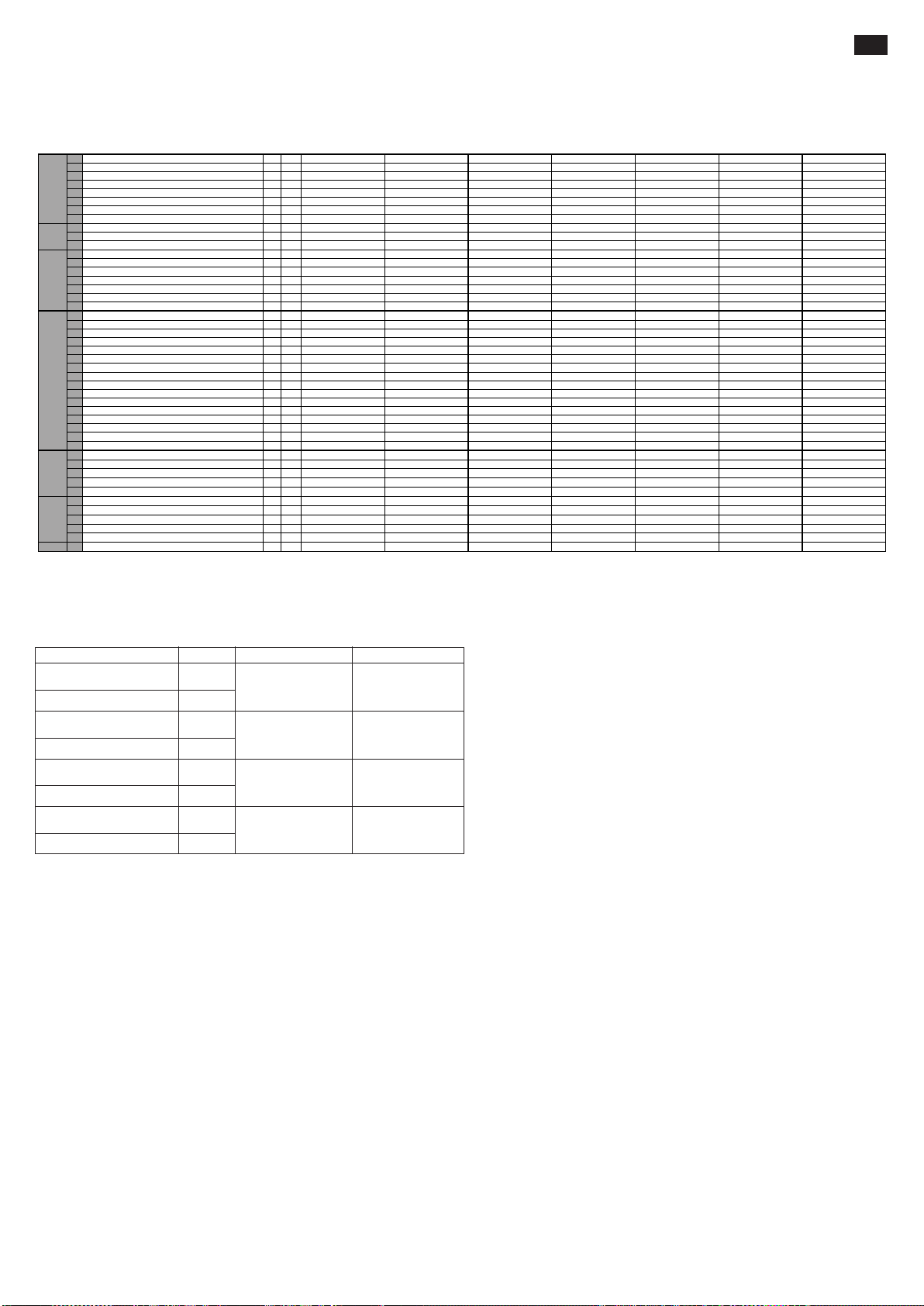
INNEHÅLL (1.1)
1.1 TILLVERKARE PR INDUSTRIAL PR INDUSTRIAL PR INDUSTRIAL PR INDUSTRIAL PR INDUSTRIAL PR INDUSTRIAL PR INDUSTRIAL
1.2 MODELL GX 12/25 III ED. BASIC GX 12/29 III ED. BASIC GX 12/35 III ED. BASIC GX 12/25 III ED. EVO GX 12/29 III ED. EVO GX 12/35 III ED. EVO GX 12/29 III ED. FL EVO
1.3 DRIVKRAFT ELEKTRISK ELEKTRISK ELEKTRISK ELEKTRISK ELEKTRISK ELEKTRISK ELEKTRISK
1.4 KÖREGENSKAPER MEDFÖLJANDE MEDFÖLJANDE MEDFÖLJANDE MEDFÖLJANDE MEDFÖLJANDE MEDFÖLJANDE MEDFÖLJANDE
1.5 BÄRFÖRMÅGA Q kg 1200 1200 1200 1200 1200 1200 1200
1.6 BARICENTRUM c mm 600 600 600 600 600 600 600
1.8 AVSTÅND MELLAN LASTHJULSAXEL OCH GAFFELBASEN x mm 780 780 780 780 780 780 780
1.9 TAKT y mm 1234 1234 1234 1234 1234 1234 1234
2.1 MASSA I DRIFT MED BATTERI (se rad 6,5) kg 530 545 578 570 585 618 615
2.2 LAST PÅ AXLARNA MED LAST, FRÄMRE/BAKRE kg 543/1187 558/1187 591/1187 583/1187 598/1187 631/1187 628/1187
2.3 LAST PÅ AXLARNA UTAN LAST, FRÄMRE/BAKRE kg 368/162 383/162 416/162 408/162 423/162 456/162 453/162
3.1 DÄCKUTRUSTNING * G+P/P G+P/P G+P/P G+P/P G+P/P G+P/P G+P/P
3.2 DIMENSIONER FRÄMRE HJUL (Ø x bredd) 250x76 250x76 250x76 250x76 250x76 250x76 250x76
3.3 DIMENSIONER BAKRE HJUL (Ø x bredd) 82x70 82x70 82x70 82x70 82x70 82x70 82x70
3.4 DIMENSIONER SIDOHJUL (Ø x bredd) 100x38 100x38 100x38 100x38 100x38 100x38 100x38
3.5 ANTAL HJUL (x=DRAGFORDON) FRÄMRE/BAKRE 1x+1/2 1x+1/2 1x+1/2 1x+1/2 1x+1/2 1x+1/2 1x+1/2
3.6 FRÄMRE VAGNBREDD
b
10
mm 565 565 565 565 565 565 565
3.7 BAKRE VAGNBREDD
b
11
mm 410 410 410 410 410 410 410
4.2 HÖJD, STÄNGD POST h1mm 1787 1987 2250 1787 1987 2250 1965
4.3 FRI HÖJD
h
2
mm - - 80 - - 80 1402
4.4 LYFTNINGSHÖJD
h
3
mm 2410 2810 3410 2410 2810 3410 2810
4.5 HÖJD, UTDRAGEN POST
h
4
mm 2992 3392 3916 2992 3392 3916 3372
4.6 STARTHÖJD
h
5
mm - - - - - - -
4.9 RODER HÖJD UNDER STYRNING MIN/MAX
h
14
mm 915/1310 915/1310 915/1310 960/1330 960/1330 960/1330 960/1330
4.15 HÖJD MED SÄNKTA GAFFLAR
h
13
mm 90 90 90 90 90 90 90
4.19 TOTAL LÄNGD
l
1
mm 1760 1760 1760 1760 1760 1760 1760
4.20 DRIVENHETENS BREDD
l
2
mm 609 609 609 609 609 609 609
4.21 TOTAL BREDD
b
1
mm 800 800 800 800 800 800 800
4.22 GAFFEL DIMENSIONER s/e/l mm 70/150/1150 70/150/1150 70/150/1150 70/150/1150 70/150/1150 70/150/1150 70/150/1150
4.24 FRONTAL GAFFELBREDD
b
3
mm 650 650 650 650 650 650 650
4.25 GAFFEL BREDD
b
5
mm 560 560 560 560 560 560 560
4.32 AVSTÅND MELLAN GAFFLAR OCH GOLV I HALVFART
m
2
mm 20 20 20 20 20 20 20
4.34 STUVNINGSKORRIDOR FÖR PALLET 800x1200 PÅ LÄNGDEN
A
st
mm 2210 2210 2210 2210 2210 2210 2210
4.35 SVÄNGRADIE
W
a
mm 1430 1430 1430 1430 1430 1430 1430
5.1 FÖRFLYTTNINGSFART, MED/UTAN LAST km/h 4,7/5,2 4,7/5,2 4,7/5,2 4,7/5,2 4,7/5,2 4,7/5,2 4,7/5,2
5.2 LYFTNINGSFART, MED/UTAN LAST m/s 0,11/0,19 0,11/0,19 0,11/0,19 0,11/0,19 0,11/0,19 0,11/0,19 0,10/0,18
5.3 SÄNKNINGSFART, MED/UTAN LAST m/s 0,12/0,15 0,12/0,15 0,12/0,15 0,19/0,19 0,19/0,19 0,19/0,19 0,16/0,14
5.8 ÖVERSTIGLIG LUTNING, MED/UTAN LAST % 5/10 5/10 5/10 5/10 5/10 5/10 5/10
5.10 FÄRDBROMS ELEKTRISK ELEKTRISK ELEKTRISK ELEKTRISK ELEKTRISK ELEKTRISK ELEKTRISK
6.1 DRIVKRAFT DRIVMOTOR kW 0,7 0,7 0,7 0,7 0,7 0,7 0,7
6.2 DRIVKRAFT LYFTMOTOR kW 2,2 2,2 2,2 2,2 2,2 2,2 2,2
6.4 BATTERI SPÄNNING NOMINELL KAPACITET V/Ah 24/85 (C20) 24/85 (C20) 24/85 (C20) 24/118 (C5) 24/118 (C5) 24/118 (C5) 24/118 (C5)
6.5 BATTERI MASSA kg 38 38 38 78 78 78 78
6.6 ENERGI FÖRBRUKNING ENLIGT VDI CYKEL kWh/h 0,9 0,9 0,9 0,9 0,9 0,9 0,9
8.4 BULLERNIVÅ FÖR FÖRAREN dB(A) 62 62 62 62 62 62 62
PRES
TEKNISKA EGENSKAPER..............................................................sid. 37
DEKLARATION AV VIBRATIONSEMISSION ...................................sid. 37
BRUK AV MASKINEN ......................................................................sid. 37
BESKRIVNING AV TRUCKEN .........................................................sid. 37
SÄKERHETSANORDNINGAR......................................................... sid. 37/38
TEKNISKA EGENSKAPER (3.46)
BESKRIVNING
VIKTER
RAM/HJULDIMENSIONER
R
TATIONE
BRICKOR ......................................................................................... sid. 38
TRANSPORT OCH MONTERING ...................................................sid. 38
BATTERI...........................................................................................sid. 38
ANVÄNDNING .................................................................................sid. 38/39
UNDERHÅLL....................................................................................sid. 39
FELSÖKNING ..................................................................................sid. 40
SV
MOTORER
ELEKTRISKA
G=Gummi, P=Polyurethane, N=Nylon
DEKLARATION AV VIBRATIONSEMISSION (33.2)
Vibrationsemissionsvärden i enlighet med EN 12096
Uppmätt
vibrationsemissionsvärde, a (m/s
Osäkerhet, K (m/s
Uppmätt
vibrationsemissionsvärde, a (m/s2)
Osäkerhet, K (m/s
Uppmätt
vibrationsemissionsvärde, a (m/s2)
Osäkerhet, K (m/s
Uppmätt
vibrationsemissionsvärde, a (m/s2)
Osäkerhet, K (m/s
2
)
2
)
2
)
2
)
Europeiska Standard (EN)
0.71
2
)
0.68
2.3
0.6
0.77
0.39
1.02
0.08
EN ISO 20643
(Hand-Arm)
EN ISO 20643
(Hand-Arm)
EN 13059
(Hela kroppen)
EN 13059
(Hela kroppen)
ProvytaBeskrivning Värde
Slätt cementgolv för
industriellt bruk
På provbana i
enlighet med
EN 13059
Slätt cementgolv för
industriellt bruk
På provbana i
enlighet med
EN 13059
Värdena bestämda i enlighet med EN ISO 20643 och EN 13059.
BRUK AV MASKINEN (4.1)
Denna maskin har utvecklats för transport och lyftning av laster på släta golv utan ojämnheter. På truckens chassis finns en identifieringsbricka som indikerar lyftkapaciteten vilken aldrig får överskridas
för personalens säkerhet och för att skydda fordonet. Vänligen observera noggrant föreskrifterna rörande säkerhet , användning och underhåll av maskinen. All montering av extrautrustning på maskinen
måste godkännas av tillverkaren.
BESKRIVNING AV TRUCKEN (5.16) (se fig.1)
Detta är en elektrisk lyft-truck med gafflar och styre. Perfekt för transport av laster på släta underlag utan lutning. Styranordningarna är väl synliga och lätta att komma åt. L rucken överensstämmer
med alla EG's aktuella komfort- och säkerhetsforeskrifter.
Figuren visar huvudegenskaperna:
1) STYRE 2) DRIVHJUL 3) HYDRAULISK CYLINDER 4) MANUELL GAFFEL UTSLÄPP 5) LYFTGAFFEL 6) A DRA STEG 7) CHASSIS 8) LYFTCYLINDER 9) HUVUDSTRÖMBRYTARE
10) ELEKTRONISKT KORT FÖR STYRNING AV GAFFEL (EVO) 11) ELEKTRONISKT KORT 12) STABILISATORHJUL 13) SKYDDSHÖLJE 14) VENTIL SOM FOREBYGGER FALL 15) BATTERI
16) ELEKTRISK BROMS 17) LASTVALSAR 18) HANDSKYDD 19) LIKRIKTARE 20) LYFTCYLINDER GAFFEL (enbart i Free Lift versionen) 21) LYFTCYLINDER MELLANLÄGE (enbart i Free Lift
versionen)
SÄKERHETSMEKANISMER (6.12) (se fig.1)
1) HUVUDSTRÖMBRYTARE (ref.9) 2) ELEKTRISK BROMS (ref.16) 3) VENTIL FÖR FLÖDESMINSKNING (ref.14) 4) VENTIL FÖR MAXIMALT TRYCK 5) SKYDD MOT STÖTAR: tjänar till att
skydda drivhjulet (ref. 2), de laterala stabilisatorhjulen (ref. 12) och de främre lastvalsarna (ref. 17) från stötar. Fötter och last är därför skyddade i händelse av olyckor. 6) "DÖD MANS GREPP" (ref.
2/fig.3); är en säkerhetströmbrytare placerad på styret och skyddar föraren från kollissioner vid backning. 7) HANDSKYDD (ref. 18) 8) ANORDNING MANUAL FÖR ATT LÅSA UPP GAFFEL (ref. 4)
Struktur (7.10)
Lyftmasten med ben och hölje bildar en mycket stark svetsad struktur (REF.7). Gafflarna styrs med precision av 4 valsar som löper längs hela masten. Drivhjulet, en pivothjul och två valsar ger trucken
en god stabilitet på 4 stödpunkter. Skyddshöljena (REF.13) är lätta att öppna och tillåter därför en bra tillgänglighet för underhåll av alla komponenter.
Drift (8.4)
Den driftenheten rör drivhjulet genom ett kugghjulssystem och cylindrar. Backen läggs i med växeln, placerad på styret (ref.1/fig.3).
Roder (9.12) (ref.1/fig.1)
Vagnen kan köras av en förare till fots. Styrningsvinkeln är 210°. Rodret agerar direkt på drivhjulet och därför ska du vrida den åt önskat håll för att byta riktning. För att aktivera vagnen (se fig.2), ska
du hålla rodret i mittläget (läge B), medan för att stoppa, ska du placera den i det övre läget (läge A) eller i det undre läget (läge C). Då du släppt rodret, återgår den automatiskt till det övre läget (läge
A) och fungerar som parkeringsbroms. I funktionssättet “sköldpadda” (långsam drift), när stydonet är i övre (pos.A) eller nedre läget (pos.C), genom att trycka på knapp “sköldpadda” (ref.8, fig.3) och
använda driftregulatorn (ref.1, fig.3), rör sig vagnen med låg hastighet.
37

Bromsar (10.7)
Färdbromsningen sker från motorn och frigör förgasaren. Den elektriska bromsen fungerar som parkeringsbroms och reservbroms. Reservbromsningen sker när dragstången förs i övre läge (pos. A)
eller nedre läge (pos. C) (se bild 2). Om elsystemet kopplas ur fungerar den elektriska bromsen som parkeringsbroms.
IHydrauliskt system (11.11)
För att höja och sänka gafflarna, använd styrets manöverknappar (ref. 4,5/fig.3) så att motorpumpen (ref.3/fig.1) skickar hydraulisk olja från tanken till lyftcylindern. Den energi som behövs för effektivt arbete fås
från batteriet (ref.15/fig.7).
Om elsystemet går sönder eller batteriet tar slut medan trucken har gafflarna upphöjda kan man sänka dem för att flytta trucken genom att ingripa på systemet för manuell utlösning (Ref.4/FIG.1) som är installerad
på solenoid ventilen.
I det hydrauliska systemet är tva säkerhetsventiler installerade:
a. Parachute-ventil som förhindrar att lasten plötsligt faller om det hydrauliska systemet skulle gå sönder. Ingår i lyftcylinder.
b. Ventil för maximalt tryck skyddar det hydrauliska och mekaniska systemen mot överbelastning. Integrerad i motorpumpen.
Elektriskt system (12.9)
Konstruerat enligt gällande regler och innefattar en elektronisk växel (ref.11/fig.1) (försedd med alla säkerhets- och justeringsinstrument) och manöverenheter
som styrs från styrets handtag. Anslutningarna är säkrade mot oförutsett avtagande. Kopparledarna är väldigt flexibla och har en diameter tillräcklig för funktionsvillkor
och för externa påverkningar som kan uppstå. Alla elektriska komponenter är monterade så att de garanterar funktion och underlättar underhåll.
BRICKOR (13.13) (se fig.4)
På maskninen finns följ rickor:
A) Identifikationsbricka som visar typen av fordon. B) Batteribricka. C) Bricka som visar lastdiagrammet i förhållande till lyfthölden och lastens bärcenter på
gafflarna. D) Brickor som visar fästpunkter. E) Brickor som varnar för risken att klämma fötterna. F) Forbjudet att använde-bricka G) Skylt som uppmanar att
läsa manualen. H) Bricka som indikerar den ungefärliga höjden av gaffeln höjes I) Merkeskilt for “skilpadde”-knapp
Observera: bripkorns får under inga pmständigheter avlägsnas eller göras oläsliga.
VIKTIGT: DET AR FÖRBJUDET ATT OVE STIGA LASTVIKTEN INDIKERAD PA BRICKAN "A" SOM ÄR FASTSATT PÅ MASKINEN VID
FÖRSÄLJNINGSTILLFÄLLET.
Notera: Detta diagram illustrerar förhållandet mellan den maximala last som kan lyftas och den relativa maximala höjden från marken under lastning
och avlastning av en pall från en avsats.
Notera: Gaffeldiagrammet här intill visar den position av lastens bärcenter som, icke desto mindre, måste fördelas så jämnt som möjligt över hela gafflarnas längd!!
TRANSPORT OCH MONTERING
Transport (14.10)
För att transportera trucken, använd de 2 fästpunkterna indikerade pa brickorna "D" (fig. 4). Maskinens tyngd visas på identifikations-brickan "A" (fig. 4).
Vi rekommenderar att ni avlägsnar de övre handskydden (ref.18, fig.1) före fastspänning för att undvika att de går sönder. Montera tillbaka skyddet innan maskinen sätts i drift. Vid transport, se till att
lyfttrucken sitter säkert så att den inte kan välta. Kontrollera att det inte läcker ut syra aller ångor ur batteriet (om sadant finnes).
Montering (15.1)
Innan maskinen startas, kontrollera att alla delar, inklusive säkerhetsanordningarna, är i perfekt kondition. Flytta trucken med batteriströmmen och aldrig med likriktad växelström. Detta för att inte
skada de elektriska komponenterna.
BATTERI (16.7)
Instruktioner, säkerhetsmått och underhåll
Inspektion, laddning och utbyte av batteriet måste utföras av auktoriserad personal och tillverkarens instruktioner måste följas. Det är förbjudet att röka eller placera lättantändligt eller gnistframkallande
material i närheten av trucken och laddaren. Rummet måste vara väl genomvädrat och komponenternas proppar måste hållas torra och rena. Torka bort syra som kan ha läckt ut, bred på lite vaselin
på kabelfästena och skruva åt dem. Batteriernas vikt och storlek kan påverka truckens stabilitet. Det är därför rekommenderat att kontakta tillverkaren för godkännande om ett batteri av annan typ än
standardbatteriet skall monteras.
Trucken monterar en batteristatusindikator som tänds när maskinen sätts igång. Om maskinen inte är i rörelse släcka denna automatiskt och tänds igen när maskinen används på nytt. Den gröna
LED-lampan indikerar att batterierna är tillräckligt laddade. När laddningsnivån börjar att bli för låg så tänds den gula lampan, vilket indikerar att det fortfarande finns en tillräcklig laddningsnivå för ett
par arbetscykler. När den återstående laddningen sjunker till under 20 % så tänds den röda lampan. I det här läget går det inte att lyfta lasten men maskinen kan förtfarande förflyttas för att nå nätuttaget
för laddning. Indikatorn aktiveras även under laddningsfasen för att ange laddningsnivån
Laddning av batteriet
Kontrollera ledarnas skick innan laddning påbörjas. Koppla in batteriladdarens sladd (A) till nätverket (se bild 3). När batteriet är laddat avbryter batteriladdaren strömtillförseln och ett grönt ljus tänds.
Dra ut sladden (A) från nätverket. En normal laddning tar från 10 till 12 timmar. Vi rekommenderar att batteriet laddas när vagnen ställs av efter skiftet. Batteriladdaren har konstruerats så att laddningen
fortsätter en viss tid efter det att batteriet är fulladdat. Det finns ingen risk för överladdning varför det inte är nödvändigt att koppla bort batteriladdaren efter avlsutad laddning.
Observera: Ladda aldrig batteriet fullt och undvik att avbryta laddningar. Låt alltid batteriladdaren avgöra när laddningen ska avbrytas. Varning: Om batterierna laddas för hårt reduceras
deras livslängd.
Batteribyte (17.4)
a) Avlägsna den bakre huven; b) Koppla bort kablarna från batteriets poler; c) Dra ut batteriet; d) Montera tillbaka batteriet i omvänd ordning och fäst det på rätt ställe och genom rätt koppling.
(Observera: ersätt alltid det gamla batteriet med ett batteri av samma typ).
VIKTIGT: HANDSKAS FÖRSIKTIGT MED SULFURSYRAN. DEN ÄR GIFTIG OCH FRÄTANDE. TVÄTTA HUD ELLER KLÄDER MED TVÅL OCH MYCKET VATTEN OM DE KOMMIT I KONTAKT
MED SYRAN. KONTAKTA LÄKARE VID OLYCKSHÄNDELSER!!
Notera: Vid byte av batteriet ska det gamla lämnas in till närmaste uppsamlingsställe.
Kontrollera batteriet
Läs noggrant igenom batteritillverkarens instruktioner för användning och underhåll. Kontrollera att det inte finns någon erosion, att det finns vaselin och att syran når 15 mm över plattorna. Om
komponenterna inte täcks, fyll på med destillerat vatten. Mät elettrolitnivåns densitet med en densimeter för att kontrollera laddnings-nivån.
ANVÄNDNING (18.17)
För att hålla sig på rimligt avstand från de farliga zonerna (såsom stolpar, gafflar, kedjor, drivhjul, drag- och stabilisatorhjul samt övriga rörliga delar) som kan orsaka att händer och/eller fötter krossas
måste föraren utföra följande användningsinstruktioner i förarpositionen.
Säkerhetsregler
Trucken måste användas enligt följande regler:
a) Maskinföraren ska ha lämplig utbildning, ha kunskap om fordonets användarhandbok, ha på sig lämpliga kläder och bära hjälm.
b) Körning av denna transpallet är tillåten endast för den som fyllt 18 år och är professionellt förberedd.
c) Föraren, som är ansvarig för trucken, måste förbjuda obehöriga att köra fordonet och se till att utomstående inte kliver upp på gafflarna.
d) Under körning måste användaren reglera hastigheten i kurvor, smala passager, portar och på ojämna golv.
e) Det är förbjudet att vistas kring truckens rörliga delar samt att kliva upp på truckens fasta delar.
f) Föraren maste undvika häftiga inbromsningar och svängar.
g) I händelse av sluttningar, med maximal tillaten lutning, måste föraren hålla lasten ovanför trucken och sakta ner farten.
h) Under körningen måste föraren se till att ha sikten fri samt att ha passagen fri vid backning.
i) Om trucken fraktas i hissar skall den föras in med gafflarna först (försäkra Er om att hissen klarar av truckens vikt).
j) Det är strängeligen förbjudet att koppla bort eller demontera säkerhetsanordningarna. Om trucken används i omgivningar där risken för olyckor eller explosioner är hög så måste densamme vara
godkänd för sadant bruk.
k) Den MAXIMALA LASTKAPACITETEN, indikerad på brickan "C" (fig.4) får under inga omständigheter överskridas. Föraren måste försäkra sig om att lasten är väl fördelad på gafflarna och i perfekt
ordning. Lasten får inte sticka ut mer än 50 mm från gafflarna.
l) Innan arbete påbörjas måste truckens förare kontrollera följande:
• Att service- och parkeringsbromsarna fungerar.
• Att lastgafflarna är i perfekt kondition.
• Att hjulen och valsarna är i bra skick.
• Att batteriet är laddat samt att batteriets komponenter är rena och torra.
• Att alla säkerhetsanordningar fungerar.
m) Avbryt användandet av trucken då batteriet signalerar att endast 20% av laddningen återstår. Ladda om batteriet. Trucken måste alltid användas och parkeras skyddad från regn eller snö.
n) Trucken får under inga omständigheter användas på mycket fuktiga platser.
o) Användningstemperatur -10°, +40°
p) Undvik att använda trucken för att dra släp eller andra vagnar
q) Signalera omedelbart eventuella skador, fel eller felfunktioner till den ansvariga personalen. Det är förbjudet att använda trucken fram till dess att den har reparerats
r) Om föraren inte har nödvändiga kvalifikationer är han/hon inte behörig att utföra reparationer på trucken och har inte tillstånd att avaktivera eller ändra säkerhetsanordningarna och brytarna
OBSERVERA: TILLVERKAREN TAR INGET ANSVAR VID SKADOR ELLER OLYCKOR ORSAKADE AV VÅRDSLÖSHET, ICKE AUKTORISERADE TEKNIKERS OFÖRMÅGA ELLER FELAKTIGT
ANVÄNDANDE AV TRUCKEN.
Förflyttning
Kontrollera att tutan och bromsen fungerar samt att batteriet är fulladdat innan trucken flyttas. Vrid nyckeln till position 1 och för styret till förflyttningsposition. Vrid reglaget långsamt åt motsatt håll än
körriktningen. Styr alltid trucken försiktigt eftersom häftiga rörelser ger upphov till farliga situationer (särskilt när trucken rör sig i hög hastighet). Minska hastigheten i trånga passager och i kurvor.
Staplande
1) Kör långsamt mot avlastningsplatsen/lagerhyllorna med lasten sänkt.
2 Försäkra Er om att truckens ben kan röra sig fritt under lastpallen samt bland lagerhyllorna. Det bästa sättet är att placera sidan av den pall som skall lyftas i linje med den senast avlastade pallen
och använda denna som referens. På detta sätt underlättas lastnings- och avlastningsarbetet.
3) Lyft lasten tills dess att denna når över hyllans nivå.
4) Rör trucken långsamt framåt och stanna då lasten befinner sig över lagerhyllan. Sänk gafflarna så att de befrias från pallen och inte vilar på det underliggande hyllplanet. Kontrollera att lasten Irer
säkert.
5) Backa långsamt och var uppmärksam på att pallen fortfarande ligger stabilt.
6) Sänk gafflarna till förflyttningsposition (FIG.6).
38
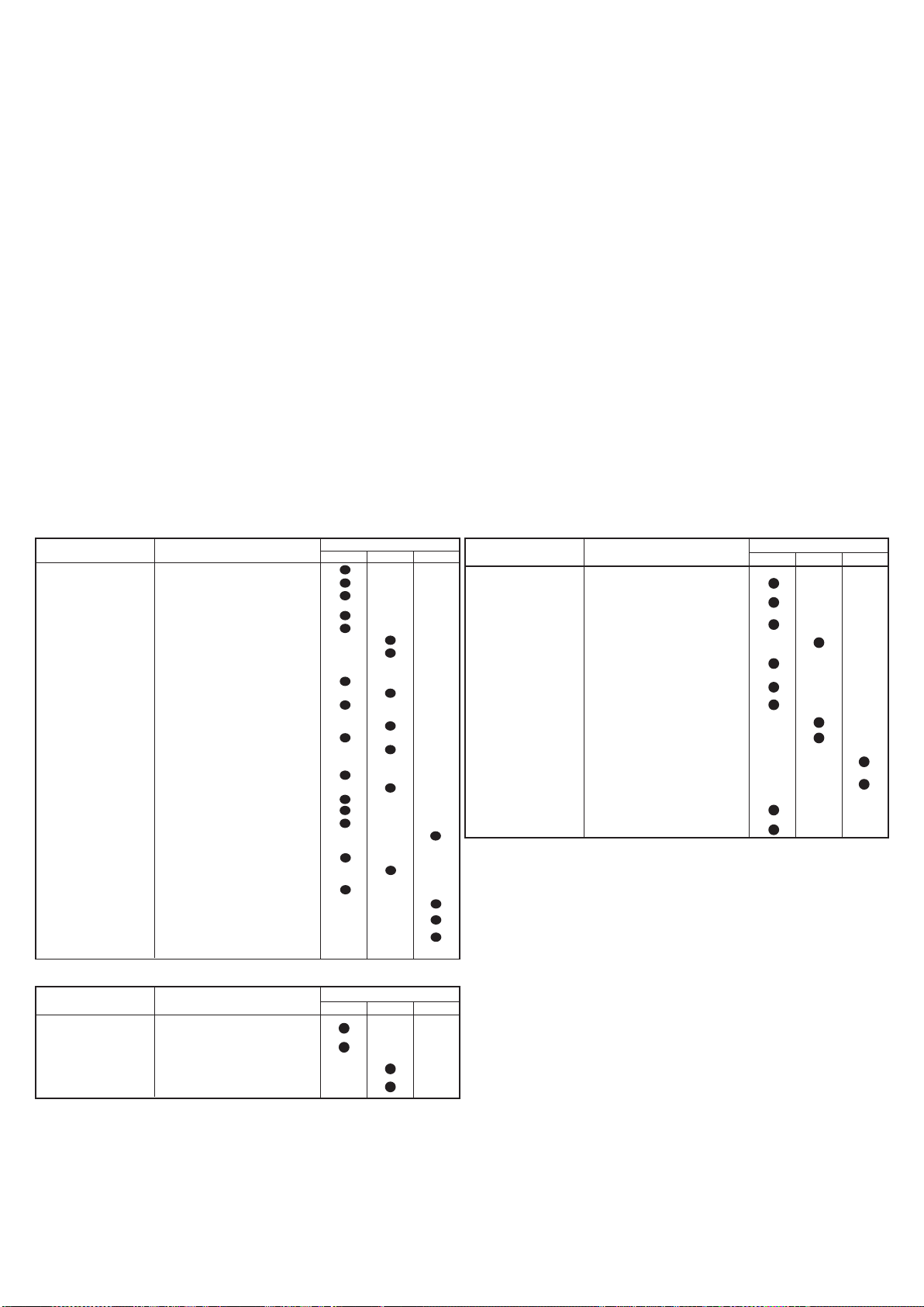
Avlastning
1 Kör långsamt mot hyllorna med gafflarna sänkta och styr in under den lägsta lastpallen. 2 Backa med gafflarna utanför pallen. 3 Höj gafflarna till önskad nivå och kör långsamt mot den pall som skall
lastas av. Kontrollera samtidigt att gafflarna utan problem får plats under pallen och att lasten är stabilt placerad på gafflarna. 4 Höj gafflarna tills att pallen lyfts från avsatsen. 5 Backa långsamt.
6 Sänk lasten långsamt och kontrollera samtidigt att gafflarna inte stöter på hinder under sänkningen.
Drift under låg hastighet (“Sköldpadde drift”)
För användning i trånga utrymmen eller för att röra sig med precision och säkerhet med delikata produkter kan man använda sig av "sköldpadde" driften. Sköldpadde driften kan enbart användas när
roderkommandot är helt upplyft. För att utnyttja driften i låg hastighet ska avsedd knapp hållas intryckt (ref.8/fig.3) på vilken en bild av en sköldpadda är återgiven, medan man för förflyttning och
gafflarnas rörelse ska använda sig av standardkommandona.
VARNING: Kontrollera alltid lastens vikt mot lyftkapaciteten relativt den höjd som är indikerad på den tillhörande brickan.
VARNING: När lasten är höjd måste styrmanövrer och inbromsningar utföras långsamt och mycket försiktigt.
Lyftblockering (28.2)
Gaffeltrucken har utrustats med en automatisk anordning som blockerar lyftet om batterierna har en urladdningsnivå som överstiger 80%. Ingreppet från säkerhetssystemet på batteri indikatorn
signaleras genom en röd lampa.
KONTROLLORGAN (19.13) (fig. 3)
1) Hastighetskontroll; 2) “Död mans grepp”; 3) Knapp ljudsignalapparat; 4) Manöverknapp för lyftning; 5) Manöverknapp för sänkning; 6) Huvudströmbrytare; 7) Batteri-varningslampa 8) Knapp ” sköldpadda”
(reducerad hastighet) 9) Batteri-varningslampa och timräkneverk
UNDERHÅLL (20.14)
Underhållsåtgärder måste utföras av specialiserad personal. Minst en gång per år måste trucken genomgå en allmän kontroll. Efter varje underhållsåtgärd måste truckens och säkerhetsanordningarnas
funktion kontrolleras. Genomför regelbundna inspektioner för att undvika att hamna i motorstopp eller i farliga situationer! (se tabell för underhåll).
Tabell för underhåll
KOMPONENT KONTROLL
STOMME OCH GAFFLAR Kontrollera bärande komponenter.
BROMSAR
HJUL Kontrollera slitage.
STYRE
ELEKTRISK SYSTEM
HYDRAULISKT SYSTEM
Kontrollera att bultar och skruvar är
åtskruvade.
Kontrollera stötar och glapp vid gafflarna.
Kontrollera funktion.
Kontrollera slitage på packning.
Kontrollera bromsstyrkan.
Kontrollera glapprummet (cirka 0,4
mm).
Kontrollera kullagers glapprum.
Kontrollera fastsättning.
Granska glapprum.
Kontrollera lateral rörelse.
Kontrollera återställning till vertikal position.
Kontrollera slitage på fjärrkontroll.
Kontrollera anslutningar och skador på
kablar.
Granska huvudströmbrytaren.
Kontrollera tutan.
Kontrollera "död mans grepp".
Granska säkringarnas skick.
Kontrollera funktion.
Kontrollera oljenivån.
Kontrollera läckage och slitage på anslutningar.
Byt olja/filter
Kontrollera funktionen på ventilen för maxtryck.
Kontrollera ventilen för in/ut-strömning.
Smörjiningstabell
SMÖRJPUNKTER
HJUL OCH VALSAR Litiumfett NLGI-2
LYFTKEDJA
MASTFÖRARE Litiumfett NLGI-2
HYDRAULISK ENHET Olja,
Litiumfett NLGI-2
SMÖRJMEDEL
ISO VG 32
PERIOD
3 månader 6 månader 12 månader
PERIOD
3 månader 6 månader 12 månader
KOMPONENT KONTROLL
CYLINDER
ELEKTRISK MOTOR
BATTERI
INSPEKTIONER
Reglering av drivhjulets höjd (Fig. 5)
Reglera drivhjulets höjd enligt följande procedur för att kompensera slitaget:
1) Montera ned den undre skyddskåpan.
2) Med styrstången i läge ”0” för du in en skruvmejsel i distanshållarens hål ref.1
och vrid styrstången i riktning ”A” (1/4 varv = 0,5 mm för avdragning av drivhjulet).
3) Dra ut skruvmejseln och vrid styrstången i riktning ”B” tills den återgår till läge
”0”.
4) Upprepa momenten i punkterna 2 och 3 så många gånger som det behövs
(Om drivhjulet är för mycket avdraget ska momenten 2 och 3 vridas i motsatt
riktning).
5) Dra åt hylsan med ref.2 mot distanshållare med ref.1 och montera tillbaka den
undre skyddskåpan.
OBS! Byt ut hjulet innan däckets slitbana är mindre än 5 mm
Kontrollera funktionsnedsättning samt
slitage på packningar.
Kontrollera trissa.
Kontrollera slitage på borstar.
Kontrollera startmotorns relä.
Kontrollera densitet och elettrolit-nivå.
(behövs inte för gelbatterier)
Kontrollera komponenternas tryck.
Kontrollera fastsättningar och kabelfästen.
Kontrollera kablarnas skick.
Smörj in kabelfästena med vaselin.
Kontrollera anslutningar till elektriskt system.
Kontrollera truckens hastighet samt
höjning och sänkning av lastgafflar.
Granska säkerhetsanordningar.
Prova höjning och sänkning med normal last.
PERIOD
3 månader 6 månader 12 månader
OBSERVERA: Använd hydraulisk olja förutom motor- och bromsolja.
Obs! Kassera den uttjänta oljan i enlighet med miljöskyddslagarna. Vi rekommenderar
att oljan samlas upp i tankar som sedan överlämnas till närmaste uppsamlingsställe.
Töm inte ut olja i naturen eller på andra olämpliga platser.
RENGÖRING AV TRUCKEN: Rengör truckens delar, förutom de elektriska och elektroniska,
med en fuktig trasa. Rengör inte med direkta vattenstänk, ånga eller lättantändliga vätskor.
De elektriska och elektroniska delarna skall rengöras med tryckluft på lågt tryck (max 5
bar), eller med en borste, dock inte av metall.
39

FELSÖKNING
MASKINEN STARTAR INTE (21.2):
BATTERIET URLADDAT LADDA BATTERIET
NEJ
MICROSTYRE TRASIGT BYT UT
NEJ
KRAFTSÄKRINGEN BRÄND
NEJ
RESERVSÄKRINGEN BRÄND
NEJ
NYCKELN TRASIG MONTERA NY NYCKEL
NEJ
KORTSLUTNING I ELEKTRISKT
SYSTEM
GAFFLARNA STANNAR INTE I HÖJD POSITION (26.1):
JA
JA
JA
JA
JA
JA
BYT UT
BYT UT
KONTROLLERA ELEKTRISKT
SYSTEM
GAFFLARNA HÖJS INTE (22.):
FÖRLUST AV OLJA I DET
HYDRAULISKA SYSTEMET
NEJ
ÖVERBELASTNING
NEJ
BATTERIET URLADDAT LADDA BATTERIET
NEJ
DET SAKNAS OLJA I TANKEN FYLL PÅ OLJA
TRUCKEN BROMSAR INTE (23.1):
LÅGT BROMSPAR JUSTERA BROMSEN
NEJ
FEL I BROMSSYSTEMET BYT UT BROMSEN
KONTROLLERA ANSLUTNINGAR
JA
JA
JA
JA
JA
JA
MINSKA LASTEN
FÖRLUST AV OLJA I DET
HYDRAULISKA OMLOPPET
NEJ
TRYCKVENTIL SMUTSIG RENGÖR VENTILEN
NEJ
UTSLITNA CYLINDERPACKNINGAR
KONTROLLERA ANSLUTNINGAR
JA
JA
JA
OCH PACKNINGAR
BYT PACKNINGAR
MOTORPUMPEN STARTAR INTE (24.1):
MOTORBORSTAR UTSLITNA BYT UT
NEJ
STARTSWITCH TRASIG BYT UT
NEJ
FELAKTIGA ELEKTRISKA
ANSLUTNINGAR
JA
JA
KONTROLLERA ANSLUTNINGAR
JA
MOTORPUMPEN STARTAR INTE (24.1):
BATTERILADDAREN ÄR INTE
KORREKT ANSLUTEN
NEJ
BATTERILADDARENS PROPP HAR
HUVUDSÄKRINGEN HAR GÅTT
GÅTT
NEJ
JA
KONTROLLERA ANSLUTNINGAR
JA
JA
DRIVHJUL VAGGA (34.2):
DRIVHJULETS HÖJD ÄR FELAKTIG
NEJ
DRIVHJULET ÄR UTSLITET
JA
JA
BYT UT
BYT UT
UTFÖR REGLERINGAR
BYT DRIVHJULETS RING
OBSERVERA!!!
OM INGEN AV DE FÖRESLAGNA LÖSNINGARNA
LÖSER FELET - TA MED ER TRANSPALLET TILL
NÄRMASTE SERVICECENTER
40
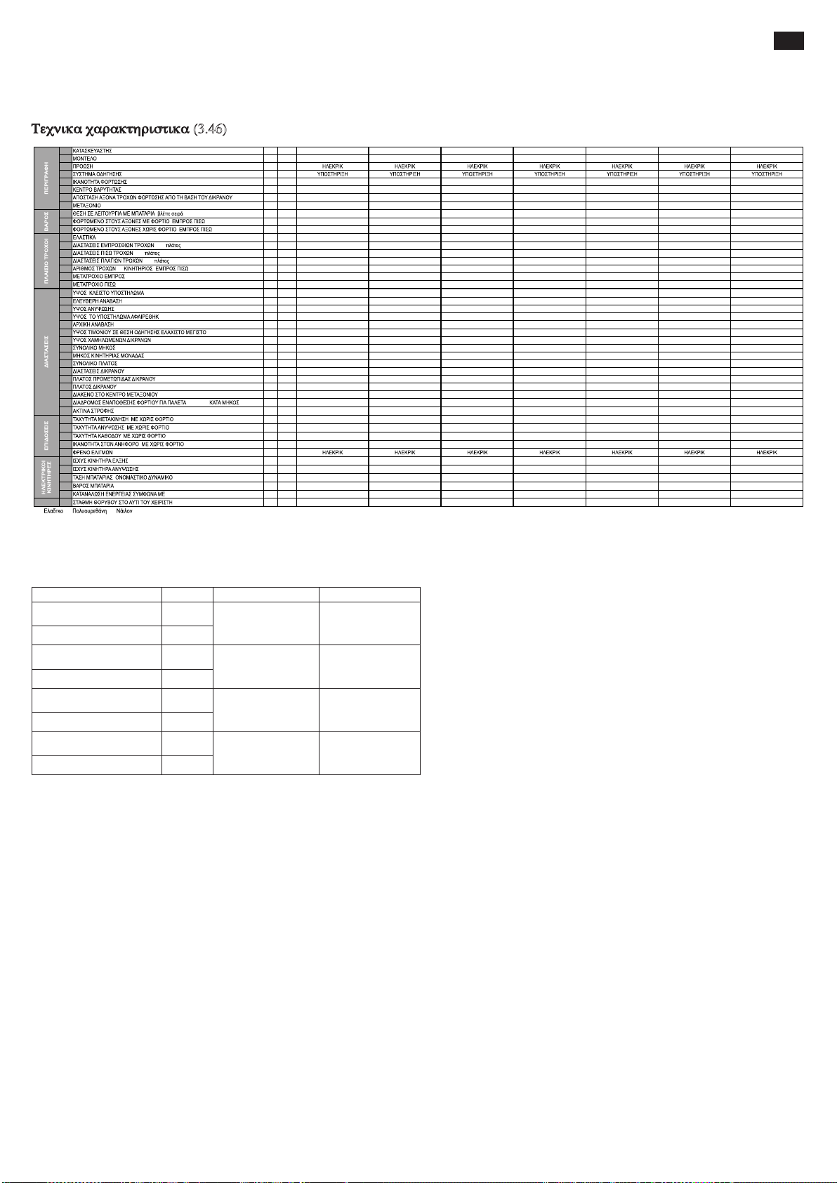
Ι ΕΡΙΕΧΟΜΕΝΑ (1.1)
1.1 PR INDUSTRIAL PR INDUSTRIAL PR INDUSTRIAL PR INDUSTRIAL PR INDUSTRIAL PR INDUSTRIAL PR INDUSTRIAL
Q kg 1200 1200 1200 1200 1200 1200 1200
c mm 600 600 600 600 600 600 600
x mm 780 780 780 780 780 780 780
y mm 1234 1234 1234 1234 1234 1234 1234
kg 530 545 578 570 585 618 615
kg 543/1187 558/1187 591/1187 583/1187 598/1187 631/1187 628/1187
kg 368/162 383/162 416/162 408/162 423/162 456/162 453/162
b
10
mm 565 565 565 565 565 565 565
b
11
mm 410 410 410 410 410 410 410
h1mm 1787 1987 2250 1787 1987 2250 1965
h
2
mm - - 80 - - 80 1402
h
3
mm 2410 2810 3410 2410 2810 3410 2810
h
4
mm 2992 3392 3916 2992 3392 3916 3372
h
5
mm - - - - - - -
h
14
mm 915/1310 915/1310 915/1310 960/1330 960/1330 960/1330 960/1330
h
13
mm 90 90 90 90 90 90 90
l
1
mm 1760 1760 1760 1760 1760 1760 1760
l
2
mm 609 609 609 609 609 609 609
b
1
mm 800 800 800 800 800 800 800
s/e/l mm 70/150/1150 70/150/1150 70/150/1150 70/150/1150 70/150/1150 70/150/1150 70/150/1150
b
3
mm 650 650 650 650 650 650 650
b
5
mm 560 560 560 560 560 560 560
m
2
mm 20 20 20 20 20 20 20
A
st
mm 2210 2210 2210 2210 2210 2210 2210
W
a
mm 1430 1430 1430 1430 1430 1430 1430
km/h 4,7/5,2 4,7/5,2 4,7/5,2 4,7/5,2 4,7/5,2 4,7/5,2 4,7/5,2
m/s 0,11/0,19 0,11/0,19 0,11/0,19 0,11/0,19 0,11/0,19 0,11/0,19 0,10/0,18
m/s 0,12/0,15 0,12/0,15 0,12/0,15 0,19/0,19 0,19/0,19 0,19/0,19 0,16/0,14
% 5/10 5/10 5/10 5/10 5/10 5/10 5/10
kW 0,7 0,7 0,7 0,7 0,7 0,7 0,7
kW 2,2 2,2 2,2 2,2 2,2 2,2 2,2
V/Ah 24/85 (C20) 24/85 (C20) 24/85 (C20) 24/118 (C5) 24/118 (C5) 24/118 (C5) 24/118 (C5)
kg 38 38 38 78 78 78 78
kWh/h 0,9 0,9 0,9 0,9 0,9 0,9 0,9
dB(A) 62 62 62 62 62 62 62
Τεχνικα χαρακτηριστικα .................................................... σελ. 41
ΔΗΛΩΣΗ ΕΚΠΟΜΠΗΣ ΔΟΝΗΣΕΩΝ................................ σελ. 41
Χρηση τησ μηχανησ ......................................................... σελ. 41
Περιγραφη τον παλλετοφορον.......................................... σελ. 41
Μηχανισμοι ασφαλειασ..................................................... σελ. 41
Πινακιδεσ.......................................................................... σελ. 42
Μεταφορα και λειτονργια .................................................. σελ. 42
Μπαταρια.......................................................................... σελ. 42
Χρηση............................................................................... σελ. 42/43
Σνντηρηση ........................................................................ σελ. 43
Ερεύνα βλαβων ................................................................ σελ. 44
(3.46)
1.2 GX 12/25 III ED. BASIC GX 12/29 III ED. BASIC GX 12/35 III ED. BASIC GX 12/25 III ED. EVO GX 12/29 III ED. EVO GX 12/35 III ED. EVO GX 12/29 III ED. FL EVO
1.3
1.4
1.5
1.6
1.8
1.9
2.1 ( 6,5)
2.2 , /
2.3 , /
3.1 * G+P/P G+P/P G+P/P G+P/P G+P/P G+P/P G+P/P
(Ø x ) 250x76 250x76 250x76 250x76 250x76 250x76 250x76
3.2
3.3
/
*G= , P= , N=
(Ø x ) 82x70 82x70 82x70 82x70 82x70 82x70 82x70
(Ø x ) 100x38 100x38 100x38 100x38 100x38 100x38 100x38
3.4
(x= ) / 1x+1/2 1x+1/2 1x+1/2 1x+1/2 1x+1/2 1x+1/2 1x+1/2
3.5
3.6
3.7
4.2 ,
4.3
4.4
4.5 ,
4.6
4.9 /
4.15
4.19
4.20
4.21
4.22
4.24
4.25
4.32
4.34 800x1200
4.35
5.1 , /
5.2 , /
5.3 , /
5.8 , /
5.10
6.1
6.2
6.4 ,
6.5
6.6 VDI
8.4
EL
ΔΗΛΩΣΗ ΕΚΠΟΜΠΗΣ ΔΟΝΗΣΕΩΝ (33.2)
Δηλωμένες τιμές εκπομπής δονήσεων σύμφωνα με την ΕΝ 12096
Επιφάνεια δοκιμής
Μετρηθείσα τιμή εκπομπής
δονήσεων, α (m/s
2
)
Αβεβαιότητα, Κ (m/s2)
Μετρηθείσα τιμή εκπομπής
δονήσεων, α (m/s
2
)
Αβεβαιότητα, Κ (m/s2)
Μετρηθείσα τιμή εκπομπής
δονήσεων, α (m/s2)
Αβεβαιότητα, Κ (m/s2)
Μετρηθείσα τιμή εκπομπής
δονήσεων, α (m/s
2
)
Αβεβαιότητα, Κ (m/s2)
Χειρολαβή Ενρωπαίκός κανόνας
0.71
0.68
2.3
0.6
0.77
0.39
1.02
0.08
ΕΝ ΙΣΟ 20643
(Χέρι -Βραχίονας)
ΕΝ ΙΣΟ 20643
(Χέρι -Βραχίονας)
ΕΝ 13059 (Ο
λόκληρο το σώμα)
ΕΝ 13059 (Ο
λόκληρο το σώμα)
Επιφάνεια δοκιμής
Δάπεδο από βιομη
χανικό λείο σκνρό
δεμα
Σε διάδρομο
δοκιμών σόμφωνα
με ΕΝ 13059
Δάπεδο από βιομη
χανικό λείο σκνρό
δεμα
Σε διάδρομο
δοκιμών σόμφωνα
με ΕΝ 13059
Τιμές πού ορίζονται βάσει των ΕΝ ΙΣΟ 20643 και ΕΝ 13059.
ΧΡΗΣΗ ΤΙΣ ΜΗΧΑΝΗΣ (4.1)
Η παρούσα μηχανη ειναι προγραμματισμενη για την ανυψωση και μεταφορα ενοσ φορτιον πανω σε επιφανειεσ λειεσ και χωρισ καμια τρχντητα Στο σκελετο βρισκεται μια πινακιδα πού δειχνει τη δννατοτη τα
ανψωσησ η οποια δεν Θα πρεπει ποτε να νπερβαινεται για την ασφαλεια τον προσωπικού και για να μην καταστραφει το παλλετοφορο.Τηρηστε ανστηρα τονσ κανονεσ προληψησ για την αποφνγη τησ κα
ταστροφησ τησ μηχανησ καθωσ επισησ κι εκεινονσ πού αφορούν στη λειτονργια και τη συντηρηση τησ Για οποιοδηποτε επιπροσθετο εξαρτημα στη μηχανη Θα πρεπει να χορηγειται αδεια απο τον κατασκε
νασεικο οικ
ΠΕΡΙΓΡΑΦΗ ΤΟΥ ΠΑΛΑΕΤΟΦΟΡ (5.16) (βλ. εικ.1)
Το παρον παλλετοφορο ειναι ενασ ηλεκτρικσ ανυψωτησ (με διχαλεσ) πού οδηγειται με τιμονι,καταλ-ληλο για την τοποΘετηση εμπορενματων σε αποθηκη και τη μεταφορα φορτιον σε επιφανειεσ επιπε-δεσ και
χωρισ καμια τραχντητα.Ολοι οι μοχλοι ειναι ενδιακριτοι και κινούνται χωρισ δνσκολια.0 αννψωτησ πληρει ολονσ τονσ υπαρχοντεσ ανεσησ και ασφαλειασ τησ ΕΕ.
Στην εικονα απεικονιζονται τα κυρ ια χαρακτηριστικα:
1) ΤΙΜΟΝΙ ΟΔΗΓΗΣΗΣ 2) ΚΙΝΗΤΗΡΑΣ 3) ΥΔΡΑΝΛΙΚΟ ΣΥΣΕΗΜΑ 4) ΑΠΟΔΕΣΜΕΥΣΗ ΤΩΝ ΠΗΡΟΥΝΙΑ ΕΓΧΕΙΡΙΔΙΟ 5) ΑΝΝΨΩΤΙΚΗ ΔΙΧΑΛΑ 6) ΔΕΥΤΕΡΟ ΠΛΑΙΣΙΟ 7) ΣΚΕΛΕΤΟΣ 8) ΑΝΥΨΩΤΙΚΟΣ
ΚΝΛΙΝΔΡΟΣ 9) ΓΕΝΙΚΟΣ ΔΙΑΚΟΠΕΗΣ 10) ΗΛΕΚΤΡΟΝΙΚΗ ΚΑΡΤΑ ΕΛΕΓΧΟΥ ΔΙΚΡΑΝΟΥ (EVO) 11) ΗΛΕΚΤΡΙΚΗ ΚΑΡΤΑ 12) ΡΟΔΑ ΑΚΙΝΙΤΟΠΟΙΗΣΗΣ 13) ΚΑΡΤΕΡ 14) ΑΝΤΙΠΤΩΤΙΚΗ ΒΑΛΒΙΔΑ
15) ΜΠΑΤΑΡΙΑ 16) ΗΛΕΚΤΡΙΚΟ ΦΡΕΝΟ 17) ΚΥΛΙΝΔΡΟΙ ΦΟΡΤΙΟΝ 18) ΠΡΟΦΝΛΑΧΤΗΡΑΣ ΧΕΡΙΩΝ 19) ΑΝΟΡΘΩΤΗΣ 20) ΚΥΛΙΝΔΡΟΣ ΑΝΥΨΩΣΗΣ ΠΗΡΟΥΝ ΟΥ (μόνο στην έκδοση Free Lift)
21) ΚΥΛΙΝΔΡΟΣ ΑΝΥΨΩΣΗΣ ΔΕΥΤΕΡΟΥ ΣΤΑΔΙΟΥ (μόνο στην έκδοση Free Lift)
ΜΗΧΑΝΙΣΜΟΙ ΑΣΦΑΛΕΙΑΣ (6.12) (βλ. εικ.1)
1) Γενικοσ διακοπτησ (Ν°9) 2) Ηλεκτρικο φρενο (Ν°16) 3) Βαλβιδα ρνθμιζομενησ ροησ (Ν°14) 4) Βαλβιδα ανωτατησ πιεσης 5) Προφνλαχτηρεσ :προστατεύούν απο τα χτυπηματα τον κινητηρα (Ν°2), τισ
πλαινε σ ροδεσ ακινητο-ποιησησ (Ν°12) και τονσ μπροοτινονσ κύλινδρούσ φορτιον (Ν°17), οποτε σε περιπτση ατυχηματοσ τα ποδια καιτο φορτιο προοτατενονται. 6) Διακοπεησ “νεκρό άτομο” (Ν°2/εικ.3):
προκειτ αι για εναν διακοπτη ασφαλειασ τοποθετη-μενο στο τιμονι οδηγησησ πού προστατεύει τον οδηγο απο τισ συγκρονσεισ σε περιπτωση οπισθο-δρομησησ. 7) Προφυλαχτηρασ χεριων (Ν°18).
8) ΑΠΟΔΕΣΜΕΥΣΗ ΤΩΝ ΠΗΡΟΥΝΙΑ ΕΓΧΕΙΡΙΔΙΟ (Ν°4).
ΔΟΜΗ (7.10)
Ο ανυψωτησ με τα στηριγματα και το προστατευτικο κουτι τησ μηχανησ σχηματιζουν μια πολυ γερη κατασκευη (Ν°7).Οι διχαλεσ οδηγουνται με ακρίβεια απο 4 κυλινδρουσ που κινουνται
καθολο το υψοσ του ανυψωτη.
Ο κινητήριος ρόδα, ο ρόδα πού ανεβοκατεβαίνουν και δυο κυλινδροι εξασφαλιζουν στο παλλετοφορο μεγαλη σταθεροτητα ,μια και στηριζεται σε 4 σημεια. Τα καρτερ (Ν°13) ανοιγουν
ευκολα και ειναι ευπροσιτα απο ολα τα συνεργεια.
ΕΛΒΗ (8.4)
Το συσεημα ελξησ ενεργοποιει την κινητηρια ροδα μεσω κωνικων οδοντωτων τροχων και κνλινδρων.Η κατεύθύνση επιλεγεται δρωντασ στισ πε ταλονδεσ πού βρισκονται στο τιμονι
οδηγησησ (Ν°1/εικ.3).
41

Τιμόνι (9.12) - (αναφ.2/Εικ.1)
Το ανυψωτικό αμαξίδιο οδηγείται από πεζό χειριστή. Η γωνία στροφής είναι 210°. Το τιμόνι ενεργεί απευθείας πάνω στον κινητήριο τροχό και επομένως για να αλλάξετε κατεύθυνση
χρειάζεται να το στρέψετε προς την επιθυμητή πλευρά. Για να ενεργοποιηθεί το ανυψωτικό αμαξίδιο (βλέπε εικ.2) το τιμόνι πρέπει να διατηρείται στην κεντρική θέση (θέση Β), ενώ για
να ακινητοποιηθεί, το τιμόνι πρέπει να μετακινηθεί στην επάνω Θέση (Θέση Α) ή στην κάτω θέση (Θέση Γ). Μόλις αφεθεί, το τιμόνι επιστρέφει αυτόματα στην επάνω θέση (Θέση Α) και
λειτουργεί ως φρένο στάθμευσης. Σε λειτουργία «χελώνας», όταν το τιμόνι είναι στην πάνω θέση (θέση Α) ή στην κάτω θέση (θέση Γ), αν πατήσετε το πλήκτρο «χελώνα» (αναφ. 8, εικ.
3) και ενεργήσετε στο ρυθμιστή λειτουργίας (αναφ. 1, εικ. 3), το αμαξίδιο κινείται με μειωμένη ταχύτητα.
Φρενο (10.7)
Το ηλεκτρομαγνητικο φρενο δρα απενθειασ στον κινητηρα ελξησ βαζοντασ το τιμονι στην ανωτατη Θεση (ΘεσηΑ)και την κατωτερη Θεση (θεσηΧ) βλ. εικ.2. Αν αδρανησει η ηλεκτρικη
εγκατασεαση το φρενο λειτούργει ωσ φρενο ακινητοποιησησ.Η δύναμη φρεναρισματοσ ρνθμιζεται δρωντασ στο μεταλλικο δακτυλιο τον φρενον οπωσ στην εικονα 3.
Υδρανλικη Εγγατασταση (11.11)
Για να σηκωσετε και να χαμηλωσετε τισ διχαλεσ αρκει να δρασετε σεονσ διακοπτεσ εντολων (Ν° 4,5/εικ.3) τον συστηματοσ τον τιμονιού με τροπο ωστε
η μηχανικη αντλ ια (Ν°3/εικ.1) να σεειλει το νδρανλικο λαδι απο το ρεζερβοναρ στον κύλινδρο ανύψωση Η απαραιτητη ενεργεια για αύτη τη δονλεια
παρεχεται απο την μπαταρια(Ν°15/εικ. 1).
Σε περίπτωση βλάβης του ηλεκτρικού συστήματος και εξάντλησης της αποθηκευμένης ενέργειας στη μπαταρία ενώ το αμαξίδιο έχει τις περόνες
ανυψωμένες, μπορείτε να κατεβάσετε τις περόμενες για να μετακινήσετε το αμαξίδιο ενεργώντας στο σύστημα χειροκίνητης απεμπλοκής (ΑΝΑΦ.4/ΕΙΚ.1)
που είναι εγκατεστημένο στην ηλεκτρική βαλβίδα.
Στην νδρανλικη εγκατασεαση ειναι τοποθετημενεσ δύο βαλβιδεσ ασφαλειασ:
α) Βαλβιδα ασφαλειας ανατροπης αλεξιπτωτο για την αποφυγη τον αποτομον πεσιματοσ τον φορτιον σε περιπτωση πού σπασει το νδρανλικο συσεημα
(ειναι τοποθετημενη στον τον κύλινδρού)
β) βαλβιδα νπερτατησ πιεσησ,ενσωματομενη στην κινητη αντλια πού προστατεύει το μηχανικο συσεημα απο την νπρεφορτωση.
Ηλεκτρικη Εγκατασεαση (12.9)
Κατασκενασμενη σύμφωνα με τονσ ισχνοντεσ κανονεσ αποτελειται απο εναν ηλεκτρονικο ρνθμιστη (11/εικ.1) πού μπορει να προγραμματιστει (πληρωντασ ολεσ
τισ ασφαλε ιεσ και τονσ κανονισμονσ) και απο μοχλονσ πού χειριζονται απο την ακρη τον τιμονιού .Οι ενωσεισ ειναι καλα στερεωμενεσ ωστε να αποφεύγεται
ενα πιθανο χαλαρωμα Οι αγωγοι ειναι πολύ ενκινητοι και εχουν την καταλληλη διαμετρο σε συνθηκεσ λειτονργιασ και σε εξωγωνεισ επηρεασμονσ πού μπορει
να προκληθούν. Ολα τα καμματια ειναι συναρμολογημενα ετσι ωστε να εξασφαλειζονν τη λειτονργια και να διευκολύνούν τη συντηρηση.
ΠΙΝΑΚΙΔΕΣ (13.13) (βλ. εικ. 4)
Πανω στη μηχανη διακρινονται οι ακολονθεσ πινακιδεσ:
a) Πινακιδα αναγνωρισησ τον τύπον τησ μηχανησ b) Πινακιδα μπαταρια c) Πινακιδα διαγραμμα φορτιον σε λειτονρ για τησ αννψωσησ και Θεση τον κεντρον βαρονσ τον φορ τιον των διχαλων d) Πινακιδεσ
δειχτεσ σημείων δεσιματοσ e) Πινακιδεσ κινδύνού σννθλιψεωσ ποδιων f) Πινακιδεσ απαγορεντικα χρησησ g) πλακετα: να διαβαστει το βιβλιαριο h) Προμήθειας δείχνοντας περίπου το ύψος στο οποίο το δίκρανο
ανυψώνεται i) Πινακιδα πού δειχνει τη Θεση τον κεντρον βαρονσ
ΠΡΟΣΟΧΗ: Οι πινακιδεσ δεν πρεπει νααφαιροννται η να μην ειναι εναναγνωστεσ.
ΣΗΜΑΝΤΙΚΟ: Απαγορεύεται το φορτιο να νπερβαινει το βαροσ πού καθοριζεται στην πινακιδα τν-πού Χ πού βρισκεται κολλημενη στο μηχανημα τη στιγμη τησ πωλησησ τον και πού κατα συνεπεια
φερει εδω.
ΠΡΟΣΕΞΤΕ: Το παρον διαγραμμα παρονσιαζει τη σχεση μεταξύ ανωτατον φορτιον πού μπορει να σηκωθει και την ανωτατη σχετικη ανύψωση απο το δαπεδο τη στιγμη τον φορτωματοσ και
ξεφορτωματοσ ενοσ φορτιον απο ενα ραφι
ΠΡΟΣΟΧΗ: Το σχεδιο τησ διχαλασ πού απεικονιζονται εδω στο πλαι δειχνει τη Θεση τον κεντρον βαρονσ τον φορτιον πού ομωσ θα πρεπει να κατανεμεται οσο το δννατο πιο ομοιομορ-φα καθολο
το μακροσ τησ διχαλασ.
ΜΕΤΑΦΟΡΑ ΚΑΙ ΕΝΕΡΓΟΠΟΙΗΣΗ
Μεταφορα (14.10)
Για την μεταφορα τον καροτσιού προβλεπονται δύο σημεια δεσιματοσ οπωσ φαινονται στισ. πινακι δεσ D (εικ.4) ενω το βαροσ τησ μηχανησ αναγραφεται στην πινακιδα αναγνωρισησ Α (εικ.4).
Πριν την πρόσδεση συστήνουμε την αφαίρεση της άνω προστασίας χεριών (Αναφ. 18, εικ. 1) για να αποφύγετε τη θραύση. Ξανατοποθετήστε την προστασία πριν θέσετε τη μηχανή σε λειτουργία.
Είναι θεμιτό, κατά τη μεταφορά, να ασφαλίζετε σταθερά το ανυψωτικό μηχάνημα έτσι ώστε να μην μπορεί να ανατραπεί. Βεβαιωθείτε ότι από την μπαυαρία (αν υπαταρία) δεν βγαίνουν οξύ ή ατμοί.
Ενεργοποιηση (15.1)
Πριν ενεργοποιησετε τη μηχανη ελεγξτε αν ολα τα μερη βρισκονται σε αψογεσ συνθηκεσ,εξακριβωστε τη λειτονργια ολων των συοτηματων και την ακεραιοτητα τον συσεηματοσ ασφαλειασ. Μετακινειτε το παλλετοφορο
με το πενμα τησ μπαταριασ και ποτε με το εναλλασσομενο ρεύμα για να μην καταστρεψετε τα ηλεκτρικα μερη.
ΜΠΑΤΑΡΙΑ (16.7)
Οδηγιεσ, μετρα ασφαλειασ και συντηρησησ.
Η εξεταση,η φορτιση και η αλλαγη τησ μπαταριασ πρεπει να γινεται απο εξειδικενμενο προσωπικο α-κολονθοντασ τισ οδηγιεσ χρησησ τον κατασκεναστη τησ μπαταριασ. Απαγορεύεται το καπνισμα καθωσ και το
να φνλλασσονται κοντα στο παλλετοφορο και το φορτωτη ενλεκτα νλικα η νλικα πού προκαλούν σπινθηρεσ. Το περιβαλλον πρεπ ει να αεριζεται πολύ καλα. Για την καλη συντηρηση οι πολοι πρεπει να ειναι στεγνοι
και καθαποι. Αφαιρεστε το οξύ πού εχει νπερχειλισει και αλειψτε με λιγη βαζελινη μι α μεγγενη και σφιξτε τεσ Το βαροσ και οι διαστασεισ τησ μπαταριασ μπορούν να επηρεασονν τη σταθεροτητα τον παλλετοφορον,
οποτε αν τοποθετηθει μια μπαταρια διαφ ορετικη απο αύτη τη στανταρ Θα πρεπει να ζητηθει απο τον κατασκεναστικο οικο η απαραιτητη εγκριση.
Το αμαξίδιο διαθέτει ένα δείκτη κατάστασης μπαταρίας που ανάβει όταν η μηχανή τίθεται σε λειτουργία. Σε περίπτωση αδράνειας της μηχανής σβήνει αυτόματα και ανάβει ξανά όταν η μηχανή είναι πάλι σε χρήση.
Η πράσινη ενδεικτική λυχνία δείχνει ότι οι μπαταρίες είναι φορτισμένες επαρκώς. Όταν η στάθμη φόρτισης καθίσταται ανεπαρκής ανάβει το κίτρινο φως, δείχνοντας ότι η φόρτιση είναι επαρκής μόνο για κάποιους
κύκλους εργασίας ακόμη. Όταν η φόρτιση πέσει κάτω από το 20% ανάβει το κόκκινο φως. Σε αυτήν την κατάσταση δεν μπορεί να αντέξει το φορτίο αλλά η μηχανή μπορεί ακόμη να μετακινηθεί για να φτάσει την
πρίζα για την επαναφόρτιση. Ο δείκτης ενεργοποιείται και κατά τη φάση επαναφόρτισης για να δείχνει την πρόοδο της φόρτισης.
Φόρτιση μπαταρίας
Πριν από την έναρξη της φόρτισης, ελέγξτε την ακεραιότητα των αγωγών.
Βάλτε το φορτιστή μπαταριών (Α) στην πρίζα βλέπε εικ. 3). Κατα την ολοκλήρωση της φόρτισης ο φορτιστής μπαταριών διακόπτει την παροχή ρεύματος φωτίζοντας την πράσινη ενδεικτική λυχνία. Βγάλτε το
φορτιστή (Α) από την πρίζα. Μια κανονική επαναφόρτιση απαιτεί από 10 έως 12 ώρες. Είναι καλύτερα να ξαναφορτίσετε τη μπαταρία όταν ολοκληρώσετε τις ώρες χρήσης τον αμαξιδίον.
Ο φορτιστής μπαταρίας είναι σχεδιασμένος για να διασφαλίζει μια φόρτιση που να διατηρείται για ορισμένο χρόνο μετά από την πλήρη φόρτιση. Δεν υφίσταται κανένας κίνδυνος υπερφόρτωσης και επομένως δεν
είναι απαραίτητη η αποσύνδεση του φορτιστή μπαταρίας μετά από την πλήρη φόρτιση.
ΠΡΟΣΟΧΗ: Μην αδειαζετε ποτε τισ μπαταριεσ τελιωσ και αποφεύγετε τισ ημιτελεισ φορτισεισ.
Επιπλεον αφηνετε παντοτε το φορτιστη να σημανει το τελοσ τησ φορτισησ
Αλλαγή μπαταρίας (17.4)
(α) Απομακρύνετε το πίσω καπό (του κιβωτίου μπαταρίας). (β) Βγαλτε τονσ ηλεκτρογορονσ αγωγονσ απο τονσ πολονσ τησ μπαταριασ. (γ) Βγαλτε την μπαταρια απο το πλαι δ) Επανατοποθετήστε την μπαταρία
ακολουθώντας την αντίστροφη κατά σειρά διαδικασία και στερεώστε την στη Θέση της φροντίζοντας να συνδεθεί σωστά.
ΠΡΟΣΟΧΗ Να βαζετε παντα μια μπαταρια ιδιον τύπον με αύτη πού αντικαθισταται.
ΣΗΜΑΝΤΙΚΟ: Να χρησιμοποιειτε με προσοχη το σολφορικο οξύ, ειναι τοξικο και διαβρωτικο.Κολλαει στο δερμα και στα ρούχα και Θα πλενονται με σαπούνι και αφθονο ν ερο.Σε περιπτωση ατνχηματοσ
συμβονλεντειτε τον γιατρο σασ!!!
ΠΡΟΣΟΧΗ Σε περίπτωση αντικατάστασης της μπαταρίας παραδώστε την παλιά μπαταρία στο πλησιέστερο κέντρο συλλογής.
Ελεγχοσ τησ Μπαταριασ
Διαβαστε με προσοχη τισ οδηγιεσ χρησησ και σνντηρησησ τον κατασκεναστη τησ μπαταριασ. Ελεγξτε οτι ειναι αδιαβρωτη και οτι υπαρχει βαζελινη και οτι το οξύ φτανει 15 μμ πανω στισ πλακεσ. Αν οι πολοι δεν
ειναι καλνμενοι γεμιστε με αποοστειρωμενο νερο. Μετρηστε την πνκνοτητα τον ηλεκρτολντη με ενα πυκνομετρο για να ελεγξετε τ ο επιπεδο φορτιση.
ΧΡΗΣΗ (18.17)
0 οδηγοσ Θα πρεπει να ακολούθει τισ οδηγιεσ χρησησ.0α πρεπει ,δηλαδη να επιτελει το εργο τον με τροπο ωστε να παραμενει μακρια απο τισ επικινδννεσ ζωνεσ για τα χερια και/η για τα ποδια ,οι ο ποιεσ ει ναι
σκελετοι, διχαλεσ,αλυσιδεσ,τριχαλιεσ,ροδεσ κινητηριεσ η ακινητοποιησησ και καθε αλλο κινούμενο μεροσ τισ μηχανησ.
ΚΑΝΟΝΕΣ ΑΣΦΑΛΕΙΑΣ
Το παλλετοφορο πρεπει να χρησιμοποιειται υπο τονσ ακολούθούσ ορονσ:
a) Ο οδηγός της μηχανής πρέπει να είναι επαρκώς εκπαιδευμένος, να γνωρίζει τις οδηγίες χρήσης του οχήματος, να φορά κατάλληλα ρούχα και να φορά κράνος.
b) 0 οδηγοσ,νπενΘννοσ γιατο παλλετοφορο,πρεπει να απαγορεύει σεουσ ανειδικεύτούσ την οδηγηση τον μεσου και να προσεχει ωστε να μην ανεβαινει κανεισ στο νποποδιο.
c) Κατα τη διαρκεια τησ οδηγησησ ο οδηγοσ Θα πρεπει να ρνθμιζει την ταχύτητα στισ στροφεσ,στα στενα περασματα,στισ πορτεσ η σε ανωμαλα πατωματα.0α πρεπει να απομακρύνει απο την περιοχη οπού
κινειται το παλλετοφορο στονσ ανειδικεύτούσ και να προειδοποιει αμεσωσ οταν νπαρχονν ανθρωποι πού κινδννενονν.Στην περιπτωση που πα ρολο την προειδοποιηση υπαρχει ακομη καποιοσ στην περιοχ η
τησ εργασιασ,ο οδηγοσ ειναι υπο χρεωμενοσ να σταματησει αμεσωσ το παλλετοφορο.
d) Απαγορεύεται η σταση στισ περιοχεσ οπού υπαρχει κινηση καθωσ επισησ και το ανεβασμα πανω στα σταθερα μερη τον παλλετοφορον.
e) .0 οδηγοσ Θα πρεπει να αποφεύγει τισ αποτομεσ στασεισ και τισ γρηγορεσ αλλαγεσ ταχυτητασ.
f) Σε περιπτωση ανοδον η καθοδον με τη μεγαλυτερη επιτρεπομενη κλιση ο οδηγοσ Θα πρεπει να εχει το φορτιο σε σωρο και να μειωσει την ταχύτητα.
g) Κατα τη διαρκεια τησ οδηγησησ ο οδηγοσ Θα πρεπει να προσεχει ωστε να εχει καλη ορατοτητα και ελεύθερο χωρο κατα τη διαρκεια τησ οπισθεν.
h) Αν το παλλετοφορο μεταφερεται με ανελκνστηρεσ πρεπει να μπει με τισ διχαλεσ φορτωματοσ μπρο στα (αφού βεβαια ελεγθει οτι η δννατοτητα τον ασανσερ ειναι επαρκεισ).
i) Απαγορεύεται ανστηρα να τιθονται εκτοσ λειτονργιασ η να αποσυνδεονται οι συσκενεσ ασφαλεια Αν το παλλετοφορο κινειται σε περιβαλλον με νψηλο κινδννο πνρκγιασ η εκρηξησ Θα πρεπει να εχει εγ κριθει
μια τετοια χρηση.
j) Η ανωτατη ικανοτητα βαρονσ που αναγραφεται στην πινακίδα Α δεν πρεπει σε καμια περιπτωση να νηερβαινεται. Ο οδηγοσ πρεπει να βεβαιωνεται οτι το φορτίο ειναι καλα τοηοθετημενο στισ διχαλεσ και σε
ηληρη ταξη. Μην τοποθετείται τιποτα πού να εξεχει απο τισ ακρεσ πανω απο 50μμ.
k) Απαγορενεται να μετακινειτε το παλλετοφορο με τισ διχαλεσ σηκωμενεσ ψηλα ,επιτρεπεται μονο σε μανονβρεσ για την τοποθετηση η για το σηκωμα τον φορτίου.
l) Πριν αρχεισει τη δονλει ο οδηγοσ τον παλλετοφορον Θα πρεπει να ελεγχει:
• τη λειτονργια τον βοηθητικού και ακινητοποιητικον φρενον.
• ωστε οι διχαλεσ φορτωματοσ να ειναι σε αριστη κατασταση.
• οι ροδεσ και οι κύλινδροι να ειναι ακεραιοι.
• η μπαταρια να ειναι φορτισμενη ,στερεωμενη καλα και οι πολοι να ειναι στεγνοι και καθαροι.
• ωστε να λειτουργούν ολα τα συστηματα ασφαλειας.
m) Διακόψτε τη χρήση τον αμαξιδίον και βάλτε το να ξαναφορτίσει όταν ο δείκτης κατάστασης της μπαταρίας (αναφ.7/εικ.3) έχει την κόκκινη ενδεικτική λυχνία αναμμένη.
n) Τ ο παλλετοφορο θα πρεπει παντα να χρησιμοποιείται η να σεαθμενεται προφνλαγμενο απο τη βροχη, το χιονι και δεν Θα πρεπει να ειναι εκτεθειμενο σε πολυ νγρεσ περιοχεσ.
o) Οερμοκρασια χρησησ 0°C+40°C.
p) Αποφύγετε τη χρήση του αμαξιδίου για την έλξη ρυμουλκούμενων ή άλλων αμαξιδίων.
q) Ενημερώστε το αρμόδιο προσωπικό άμεσα για τυχόν ζημιές, βλάβες ή δυσλειτουργίες. Απαγορεύεται η χρήση του αμαξιδίου μέχρι την επισκευή του.
r) Αν ο οδηγός δεν έχει τα απαραίτητα προσόντα δεν επιτρέπεται να πραγματοποιήσει επισκευές στο αμαξίδιο, να απενεργοποιήσει ή να τροποποιήσει τις συσκευές ασφαλείας και τους διακόπτες.
42

Χ ΠΡΟΣΟΧΗ: Ο κατασκεναστικοσ οικοσ δεν φερει καμια ευθύνη σχετικα με τισ βλαβεσ που οφειλονται σε αδιαφορία, ανικανοτητα, τοποθετηση απο μη εξειδικενμενονσ τεχ νικονσ και
ακαταλληλη χρηση τον παλλετοφορου.
ΜΕΤΑΦΟΡΑ
Πριν μετακινησετε το παλλετοφορο ελεγξτε τη λειτονργια τον κουδουνιού ,τον φρενον και την μπαταρια να ειναι εντελωσ γεματη .Γνριστε το κλειδι στη Θεση 1 και φερτε ρο τ ιμονι
στη Θεση τησ μετακινησησ .Γνριοτε το ρνθμιστη αργα και κατενθννθειτε προσ την κατεύθύνση πού επιθυμειτε.Για να η για να σταματησετε εντελωσ γνρισεε το ρνθμισ τη προσ την
αντιθετη φορα απο εκεινη τησ ταχντητασ.Με το παλλετοφορο σεριβετε παντα πρσεχτικα μια και κινησεισ αποτομεσ ειναι αιτιεσ για την προκληση επικινδύνων κ ατασεασεων (συγκεκριμενα
οταν το παλλετοφορο κινειται με μεγαλη ταχύτητα .Μετακινεισεε παντα μετο φορτιο σε χαμηλη Θεση και μειωνετε ταχύτητα στα σεενα περασματ α και σεισ σεροφεσ.
ΚΑΘΕΤΗ ΤΟΠΟΘΕΤΗΣΗ ΦΟΡΤΙΟΥ
1) Κινηθειτε προσεχτικα προσ τα ραφια με το φορτιο σε Θεση χαμηλη.
2) Βεβαιωθειται οτι τα ποδια τον παλλετοφορον εχουν ενα ελεύθερο περασμα κατω απο το φορτιο η τα ραφια .0 καλντεροσ τροποσ ειναι να βαλετε σε απολντη ενθεια την πλενρα τον
φορτιον πού προκειτα ι να ανυψωσετε με την πλενρα τον ραφιού περνοντασ το ωσ σημειο αναφορασ. Με αύτο τον τροπο η δονλεια τοποθετησησ και ξεφορτωματοσ Θα ειναι πιο εύκολη
3) Ανασηκωοτε το φορτιο ωστε να ξεπερναει ελεύθερα το επιπεδο τησ επιφανειασ τον σημειον τοποΘε τησησ
4) Κινηστε αργα προσ τα εμπροσ και σταματατε οταν το φορτιο βρισκεται πανω απο το ραφι.Σε αύτο το σημειο χαμηλωνετε τισ διχαλεσ ωστε να ελενθεροθον απο την επιφανεια τον
σωρού τον φορτιον κ αι να μην πιεζονν την επιφανεια τον ραφιού πού βρισκεται απο κατω.Ελεγξτε οτι το φορτιο εχει σιγουρα τοποθετηθει.
5) ΚινηΘειτε αργα προσ τα πισω προσεχοντασ ωστε το φορτιο να παραμενει καλα τοποθετημενο.
6) Κατεβαστε τισ διχαλεσ στη Θεση τησ μετακινησησ (φιγ.6).
ΒΕΦΟΡΤΩΜΑ
1) Με τισ διχαλεσ κατεβασμενεσ και καθετεσ πλησιαζετε στο ραφι και μπαινετε κατω απο το τελευταιο φορτίο.
2) Γνριζετε με τισ διχαλεσ εξω απο το φορτιο .
3) Σηκωνετε τισ διχαλεσ στο επιθυμητο νψοσ και κινειστε αργα ωσ προσ το φορτιο πού ειναι για να ξεφορτωσετε .Την ιδια σειγμη προσεχετε ωστε οι διχαλεσ να μπαινονν κατω απο το
φορτιο χωρισ δνσκο λια και οτι το φορτιο ειναι τοποθετημενο με ασφαλεια πανω στισ διχαλεσ.
4) Σηκωνετε τισ διχαλεσ ωσπον να σηκωσετε το φορτιο απο την επιφανεια τον ραφιού .
5) Κινειστε αργα προσ τα πισω στο διαδρομο.
6) Κατεβαζετε αργα το φορτιο ενω προσεχετε ωστε οι διχαλεσ να μην βρισκονν κανενα εμποδιο κατα τη διαρκεια τησ καθοδον.
Τρόπος χρήσης με μειωμένη ταχύτητα ("Χελώνα")
Για χρήση σε στενούς χώρους ή για ασφαλή μεταφορά ακριβείας ευαίσθητων εμπορευμάτων μπορείτε να χρησιμοποιήσετε τον τρόπο λειτουργίας "χελώνας". Ο τρόπος λειτουργίας
"χελώνας" μπορεί να χρησιμοποιηθεί μόνο με το τιμόνι ελέγχου πλήρως ανυψωμένο. Για τις εργασίες με λειτουργία με μειωμένη ταχύτητα κρατήστε πατημένο το ειδικό πλήκτρο
(αναφ.8/εικ.3) όπου εικονίζεται το πικτόγραμμα μιας χελώνας και ενεργήστε στα πλήκτρα για τη μετατόπιση και την κίνηση των περονών όπως γίνεται και στις εργασίες με τυπικό
(standard) τρόπο λειτουργίας.
ΠΡΟΣΟΧΗ:Ελεγχετε παντα το βαροσ τον φορτιον ωσ προσ τη δννατοτητα αντοχησ οπωσ αύτη νποδεικνυεται στην πανακιδα.
ΠΡΟΣΟΧΗ:Οταν το φορτιο ειναι ανυψωμενο στριβετε και φρεναρετε αργα και με πολύ προ-σοχη.
Μπλοκα∋ρισµα της αναση∋κωσης (28.2)
Το καρο’τσι (κλαρκ) διαθε’τει µιαν αυτο’µατη δια’ταξη που µπλοκα’ρει την αναση’κωση του φορτι’ου µε το που φτα’νουν οι µπαταρι’ες σε επι’πεδο εκφο’ρτισης ανω’τερο του 80%.
ΜΕΡΗ ΧΕΙΡΙΣΜΟΥ (19.13) (ΕΙΚ.3)
1. Ρυθμισεησ ταχντητασ 2. Διακοπεησ “νεκρό άτομο” 3. Διακοπεησ ηχητικου σησεηματοσ 4. Διακοπεησ ανυψωσησ 5. Διακοπεησ καθοδον 6. Γενικοσ διακοπτησ 7. Δειχτησ καταστασησ μπαταρίας
8. Κουμπί "χελώνα" (αργή ταχύτητα) 9. Οθόνη της κατάστασης της μπαταρίας και ώρα
ΣΥΝΤΗΡΗΣΗ (20.14)
Η συντηρηση πρεπει να πραγματοποιειται απο εξειπεικενμενο προσωπικο. Το παλλετοφορο Θα πρεπει να υποβαλλεται σε γενικο ελεγχο τουλαχιστον μια φορα το χρονο Μετα απο καθε συντηρηση
Θα πρεπει να εξακριβωνεται η λειτονργια τον παλλετοφορου και των συστηματων ασφαλειασ Υποβαλλετε το παλλετοφορο σε περιοδικονσ ελεγχονσ για να καταοτραφει η μηχανη και για την ασφαλεια
τον προσωπικού (βλ. πινακιδα συντηρηση).
ΠΙΝΑΚΑΣ ΣΥΝΤΗΡΗΣΗΣ
Ρύθμιση ύψους κινητήριου τροχού (Εικ. 5)
Ρυθμίστε το ύψος του κινητήριο τροχού τηρώντας την παρακάτω
διαδικασία για να αντισταθμίσετε τη φθορά του:
1) Αφαιρέστε το κάτω κάρτερ προστασίας,
2) Με το τιμόνι στη θέση “0” εισάγετε ένα κατσαβίδι στην οπή του
αποστάτη αναφ.1 και περιστρέψτε το τιμόνι προς την κατεύθυνση “A”
(1/4 γύρο = 0,5 mm μετακίνησης του κινητήριου τροχού),
3) Αφαιρέστε το κατσαβίδι και περιστρέψτε το τιμόνι προς την
κατεύθυνση “B” μέχρι να επιστρέψετε στη θέση “0”,
4) Επαναλάβετε τις εργασίες στα σημεία 2 και 3 όσες φορές είναι
αναγκαίο (Αν ο κινητήριος τροχός έχει αφαιρεθεί υπερβολικά
επαναλάβετε την εργασία 2 και 3 περιστρέφοντας προς την αντίθετη
κατεύθυνση),
5) Σφίξτε τη στεφάνη αναφ.2 κόντρα στον αποστάτη αναφ.1 και
επανασυναρμολογήστε το κάτω κάρτερ προστασίας.
ΠΡΟΣΟΧΗ Αντικαταστήστε τον τροχό πριν το πάχος του πέλματος είναι
μικρότερο από 5 χιλιοστά.
ISO VG 32
ΠΡΟΣΟΧΗ :Χρησιμοποιηστε λαδι νδρανλικο εκτοσ λαδι μηχανησ και φρενων.
Σημείωση: η διάθεση του χρησιμοποιημένου λαδιού πρέπει να γίνεται με σεβασμό
προς το περιβάλλον. Συμβουλεύουμε τη συλλογή του λαδιού σε δοχεία που θα
παραδίδονται στη συνέχεια στο πλησιέστερο κέντρο συλλογής. Μην ριχνετε το λαδι
στο εδαφοσ η σε ακαταλληλουσ τοπονσ.
ΠΑΛΛΕΤΟΦΟΡΟΥ: ΚαΘαριστε τα σημεια τον παλλετοφορον,εκτοσ απο αυτα πού
ει-ναι ηλεκτρικα η ηλεκρρονικα με ενα νγρο πανι .Μην το καθαριζετε πετωντασ
απενΘειασ νερο,ατμο και εύφλεκτα υγρ α. Καθα ιζετε τα ηλεκτρικα και ηλεκτρονικα
μερη με συμριεσμενο αερα χωρισ νγρασια με χαμηλη π ιεση (μαξ 5 βαρ),η με ενα
πινελο μη μεταλλικο.
43

ΑΝΑΖΗΤΗΣΗ ΒΛΑΒΩΝ
Η ΜΗΧΑΝΗ ΔΕΝ ΞΕΚΙΝΑΕΙ (21.2): ΟΙ ΔΙΧΑΛΕΣ ΔΕΝ ΑΝΥΨΩΝΟΝΤΑ (22.1):
ΤΟ ΠΑΛΛΕΤΟΦΟΡΟ ΔΕΝ ΦΡΕΝΑΡΕΙ (23.1):
ΟΙ ΔΙΧΑΛΕΣ ΔΕΝ ΠΑΡΑΜΕΝΟΥΝ ΣΗΚΩΜΕΝΕΣ (26.1):
Η ΜΗΧΑΝΙΚΗ ΑΝΤΛΙΑ ΔΕΝ ΞΕΚΙΝΑ (24.1)
Η ΜΠΑΤΑΡΙΑ ΔΕΝ ΦΟΡΤΙΖΕΤΑΙ (25.1):
Ο ΚΙΝΗΤΗΡΙΟΣ ΤΡΟΧΟΣ ΟΛΙΣΘΑΙΝΕΙ (34.2):
ΤΟ ΥΨΟΣ ΚΙΝΗΤΗΡΙΟΥ ΤΡΟΧΟΥ
ΔΕΝ ΕΙΝΑΙ ΣΩΣΤΟ
NAI
ΦΘΑΡΜΕΝΟΣ ΚΙΝΗΤΗΡΙΟΣ ΤΡΟΧΟΣ
OXI
OXI
ΠΡΟΧΩΡΗΣΤΕ ΣΕ ΡΥΘΜΙΣΗ
ΑΝΤΙΚΑΤΑΣΤΗΣΤΕ ΤΟ ΔΑΚΤΥΛΙΟ
ΤΟΥ ΚΙΝΗΤΗΡΙΟΥ ΤΡΟΧΟΥ
ΠΡΟΣΟΧΗ
Αν καμια απο τισ προτεινομενεσ λνσεισ δεν
διορθωνονν τηβλαβη, πηγαινετε το
παλλετοφορο στο πλησιεστερο συνεργει
44

YHTEENVETO (1.1)
1.1 VALMISTAJA PR INDUSTRIAL PR INDUSTRIAL PR INDUSTRIAL PR INDUSTRIAL PR INDUSTRIAL PR INDUSTRIAL PR INDUSTRIAL
Q kg 1200 1200 1200 1200 1200 1200 1200
c mm 600 600 600 600 600 600 600
x mm 780 780 780 780 780 780 780
y mm 1234 1234 1234 1234 1234 1234 1234
kg 530 545 578 570 585 618 615
kg 543/1187 558/1187 591/1187 583/1187 598/1187 631/1187 628/1187
kg 368/162 383/162 416/162 408/162 423/162 456/162 453/162
b
10
mm 565 565 565 565 565 565 565
b
11
mm 410 410 410 410 410 410 410
h1mm 1787 1987 2250 1787 1987 2250 1965
h
2
mm - - 80 - - 80 1402
h
3
mm 2410 2810 3410 2410 2810 3410 2810
h
4
mm 2992 3392 3916 2992 3392 3916 3372
h
5
mm - - - - - - -
h
14
mm 915/1310 915/1310 915/1310 960/1330 960/1330 960/1330 960/1330
h
13
mm 90 90 90 90 90 90 90
l
1
mm 1760 1760 1760 1760 1760 1760 1760
l
2
mm 609 609 609 609 609 609 609
b
1
mm 800 800 800 800 800 800 800
s/e/l mm 70/150/1150 70/150/1150 70/150/1150 70/150/1150 70/150/1150 70/150/1150 70/150/1150
b
3
mm 650 650 650 650 650 650 650
b
5
mm 560 560 560 560 560 560 560
m
2
mm 20 20 20 20 20 20 20
A
st
mm 2210 2210 2210 2210 2210 2210 2210
W
a
mm 1430 1430 1430 1430 1430 1430 1430
km/h 4,7/5,2 4,7/5,2 4,7/5,2 4,7/5,2 4,7/5,2 4,7/5,2 4,7/5,2
m/s 0,11/0,19 0,11/0,19 0,11/0,19 0,11/0,19 0,11/0,19 0,11/0,19 0,10/0,18
m/s 0,12/0,15 0,12/0,15 0,12/0,15 0,19/0,19 0,19/0,19 0,19/0,19 0,16/0,14
% 5/10 5/10 5/10 5/10 5/10 5/10 5/10
kW 0,7 0,7 0,7 0,7 0,7 0,7 0,7
kW 2,2 2,2 2,2 2,2 2,2 2,2 2,2
V/Ah 24/85 (C20) 24/85 (C20) 24/85 (C20) 24/118 (C5) 24/118 (C5) 24/118 (C5) 24/118 (C5)
kg 38 38 38 78 78 78 78
kWh/h 0,9 0,9 0,9 0,9 0,9 0,9 0,9
dB(A) 62 62 62 62 62 62 62
G=Kumi, P=Polyuretaani, N=Nailon
KUVAUS
PAINOT
RUNKO/RENKAAT
SÄHKÖMOOT_T
ORIT
SUORITUSKYK
Y
MITAT
TEKNISET OMINAISUUDET...........................................................SIVU 45
TÄRINÄPÄÄSTÖILMOITUS.............................................................SIVU 45
KONEEN KAYTTÖTARKOITUS.......................................................SIVU 45
TRUKIN KUVAUS.............................................................................SIVU 45
TURVALLISUUSLAITTEET..............................................................SIVU 45/46
KILVET............................................................................................. SIVU 46
KULJETUS JA KAYTTÖÖNOTTO....................................................SIVU 46
AKKU................................................................................................SIVU 46
KÄYTTÖ ...........................................................................................SIVUT 46/47
HUOLTO...........................................................................................SIVU 47
VIKOJEN ETSINTÄ..........................................................................SIVU 48
TEKNISET OMINAISUUDET (3.46)
1.2 MALLI GX 12/25 III ED. BASIC GX 12/29 III ED. BASIC GX 12/35 III ED. BASIC GX 12/25 III ED. EVO GX 12/29 III ED. EVO GX 12/35 III ED. EVO GX 12/29 III ED. FL EVO
1.3 PROPULSIO SÄHKO SÄHKO SÄHKO SÄHKO SÄHKO SÄHKO SÄHKO
1.4 OHJAUSJÄRJESTELMÄ TALUTTETAVA TRUKKI TALUTTETAVA TRUKKI TALUTTETAVA TRUKKI TALUTTETAVA TRUKKI TALUTTETAVA TRUKKI TALUTTETAVA TRUKKI TALUTTETAVA TRUKKI
1.5 KANTOKYKY
1.6 PAINOPISTE
1.8 KUORMAPYÖRIEN AKSELIVÄLI HAARUKAN ALUSTASTA
1.9 AKSELIVÄLI
2.1 KÄYTTÖMASSA AKUN KANSSA (katso rivi 6,5)
2.2 AKSELIEN KUORMITUS KUORMAN KANSSA, ETU/TAKA
2.3 AKSELIEN KUORMITUS ILMAN KUORMAA, ETU/TAKA
3.1 RENKAAT * G+P/P G+P/P G+P/P G+P/P G+P/P G+P/P G+P/P
3.2 ETURENKAIDEN MITAT (Ø x leveys) 250x76 250x76 250x76 250x76 250x76 250x76 250x76
3.3 TAKARENKAIDEN MITAT (Ø x leveys) 82x70 82x70 82x70 82x70 82x70 82x70 82x70
3.4 SIVURENKAIDEN MITAT (Ø x leveys) 100x38 100x38 100x38 100x38 100x38 100x38 100x38
3.5 ETU/TAKARENKAIDEN LUKUMÄÄRÄ (x=VETOYKSIKKÖ) 1x+1/2 1x+1/2 1x+1/2 1x+1/2 1x+1/2 1x+1/2 1x+1/2
3.6 ETURENKAIDEN VÄLI
3.7 TAKARENKAIDEN VÄLI
4.2 KORKEUS, PYSTYTANKO KIINNI
4.3 VAPAA KORKEUS
4.4 NOSTOKORKEUS
4.5 KORKEUS, PYSTYTANKO VEDETTY ULOS
4.6 ALKUNOSTO
4.9 OHJAUSPYÖRÄN KORKEUS OHJAUSASENNOSSA MIN/MAX
4.15 LASKETTUJEN HAARUKOIDEN KORKEUS
4.19 KOKONAISPITUUS
4.20 VETOYKSIKÖN PITUUS
4.21 KOKONAISLEVEYS
4.22 HAARUKOIDEN MITAT
4.24 HAARUKOIDEN ETULEVEYS
4.25 HAARUKOIDEN LEVEYS
4.32 VAPAATILA AKSELIVÄLIN PUOLIVÄLISSÄ
4.34 PITKITTÄINEN LIIKKUMATILA 800X1200 KOKOISELLE LAVALLE
4.35 OHJAUSSÄDE
5.1 KÄÄNTÖNOPEUS KUORMALLA JA ILMAN
5.2 NOSTO NOPEUS KUORMALLA JA ILMAN
5.3 LASKU NOPEUS KUORMALLA JA ILMAN
5.8 YLITETTÄVÄ KALLISTUS KUORMALLA JAILMAN
5.10 SEISONTAJARRU SÄHKO SÄHKO SÄHKO SÄHKO SÄHKO SÄHKO SÄHKO
6.1 VETOMOOTTORIN TEHO
6.2 NOSTOMOOTTORIN TEHO
6.4 AKKUJÄNNITE, NIMELLISTEHO
6.5 AKUN PAINOT
6.6 ENERGIANKULUTUS SYKLIN VDI MUKAAN
8.4 MELUISUUS KÄYTTÄJÄN KORVIEN TASOLLA
FI
TÄRINÄPÄÄSTÖILMOITUS (33.2)
Normin EN 12096 kanssa yhdenmukaisesti ilmoitetut tärinäpäästöarvot
Mitattu tärinäpäästöarvo,
a (m/s2)
Epävarmuus, K (m/s
Mitattu tärinäpäästöarvo,
2
a (m/s
)
Epävarmuus, K (m/s
Mitattu tärinäpäästöarvo,
a (m/s2)
Epävarmuus, K (m/s
Mitattu tärinäpäästöarvo,
2
a (m/s
)
Epävarmuus, K (m/s
2
)
2
)
2
)
2
)
Eurooppalaista standardia (EN)
0.71
0.68
2.3
0.6
0.77
0.39
1.02
0.08
EN ISO 20643
(Käsi-Käsivarsi)
EN ISO 20643
(Käsi-Käsivarsi)
EN 13059
(Koko keho)
EN 13059
(Koko keho)
KoepintaKuvaus Arvo
Teollinen sileä
sementtilattia
Koeradalla normin
EN 13059 mukaan
Teollinen sileä
sementtilattia
Koeradalla normin
EN 13059 mukaan
Määritellyt arvot yhdenmukaisesti normin EN ISO 20643 ja EN 13059 kanssa.
KONEEN KÄYTTÖTARKOITUS (4.1)
Tämä kone on suunniteltu kuormien nostamiseen ja kuljettamiseen täysin tasaisilla alustoilla. Alustasta on löydettävissä tunnistuskilpi, joka osoittaa nostokapasiteetin. Työntekijöiden turvallisuuden
säilyttämiseksi ja ajoneuvon pitämiseksi vahingoittumattomana nostokapasiteettia ei saa koskaan ylittää. Pyydämme Teitä noudattamaan koneen turvallisuus-, käyttö- ja huolto-ohjeita ehdottoman
tarkasti. Minkä tahansa lisävarustuksen asentaminen koneeseen edellyttää VALMISTAJAN valtuutusta
TRUKIN KUVAUS (5.16) (katso kuva 1)
Tämä kone on sähköinen, ohjaustangon kautta ohjattava haarukkatrukki, joka soveltuu erinomaisesti erilaisten kuormien varastointiin ja kuljetukseen täysin tasaisilla alustoilla. Koneen ohjausosat ovat
hyvin näkyvissa ja niitä on helppo käytt. Trukki vastaa kaikkia EU:n mukavuus- ja turvallisuusohjeita.
Kuvasta näkyvät sen p osat:
1) OHJAUSTANKO 2) MOOTTORIN ALLA OLEVA PYORÄ 3) HYDRAULINEN KESKUS 4) KÄSIVAPAUTUSVIPU FORK 5) NOSTOHAARUKKA 6) TOINEN KERROS 7) ALUSTA
8) NOSTOSYLINTERI 9) P KYTKIN 10) NOSTOTRUKIN HALLINNAN PIIRIKORTTI (EVO) 11) ELEKTRONINEN KORTTI 12) VAKAUTTAJAPYORA 13) SUOJUKSET 14) VARMUUSVENTTIILI
15) AKKU 16) SÄHKÖJARRU 17) KUORMAPYÖRÄT 18) KÄSISUOJA 19) NOSTURI 20) HAARUKAN NOSTOSYLINTERI (vain Free Lift -mallissa) 21) TOISEN VAIHEEN NOSTOSYLINTERI (vain
Free Lift -mallissa)
TURVALLISUUSLAITTEET (6.12) (katso kuva 1)
1) P KYTKIN (numero 9) 2) SÄHKÖJARRU (numero 16) 3) YLIPAINEVENTTIILI (numero 14) 4) MAKSIMIPAINEVENTTIILI 5) PUSKURIT: suojaavat moottorin alla olevaa pyor (numero 2), sivuilla
olevia vakauttajapyöriä (numero 12) ja etummaisia kuormapyöriä (numero 17) iskuilta; täten onnettomuustapauksissa jalat ja kuorma ovat suojatut. 6) "KUOLLEEN MIEHEN" VIPU (numero 2/KUVA
3); tämä on suojakytkin , joka sijaitsee ohjaustangolla ja suojaa ajajaa yhteentörmäyksiltä peruutettaessa. 7) KÄSISUOJA (numero 18) 8) KÄSIVAPAUTUSVIPU FORK (numero 4)
Rakenne (7.10)
Nostorunko ja siihen kuuluvat jalat sekä konepelti muodostavat hyvin kestävän, hitsatun rakenteen (NUMERO 7). Koko nostorungon kattavat 4 rullalaakeria tarkkuusohjaavat haarukoita.
Vetopyörä, kääntyvä pyörä ja kaksi rullalaakeria takaavat trukin erittäin hyvän vakauden neljän tukipisteen kautta.
Suojukset (NUMERO 13) ovat helposti avattavissa, joka mahdollistaa pääsyn kaikkiin osiin konetta huollettaessa.
Ajo (8.4)
Ajoyksikkö liikuttaa kartio- ja sylinterivaihteiden kautta moottorin alla olevaa pyör. Liikkumisen suuntaa voidaan muuttaa kuristusventtiilien avulla, jotka sijaitsevat ohjaustangolla. (numero 1/ kuva 3)
Ohjaustanko (9.12) (numero 1/ kuva 1)
Kuljettaja voi ajaa vaunua seisaaltaan. Se kääntyy 210° kulmassa. Ohjaustanko ohjaa suoraan vetopyörää. Halutessasi vaihtaa suuntaa pyöritä ohjaustankoa haluamaasi suuntaan. Vaunu käynnistetään
(kts kuva 2) pitämällä ohjaustanko keskiasennossa (asento B) ja se pysäytetään siirtämällä ohjaustanko ylä- (asento A) tai ala-asentoon (asento C). Vapauttaessasi ohjaustangon se siirtyy automaattisesti
yläasentoon (asento A) ja toimii parkkijarruna. Toimintatavassa “kilpikonna” (hidas), kun ohjauslaite on yläasennossa (as.A) tai ala-asennossa (as.C), painamalla “kilpikonna”-näppäintä (rif.8, kuva 3)
ja käyttämällä käyntinopeuden säädintä (viite 1, kuva 3), vaunu liikkuu matalalla nopeudella.
45
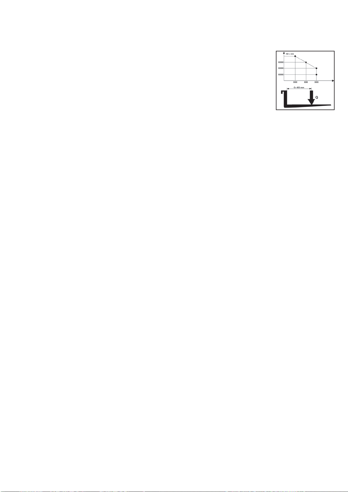
Jarrut (10.7)
Kaasupoljinta nostamalla jarrutus tapahtuu moottorin välityksellä. Pysäköintijarru sekä hätäjarru toimivat sähkömagneettisen jarrun välityksellä. Hätäjarrutus toimii, kun ohjaustanko käännetään
yläasentoon (A) tai ala-asentoon (C) (kuva 2). Kun sähköjärjestelmä suljetaan pois päältä, sähkömagneettinen jarru toimii pysäköintijarrun tavoin.
Hydraulinen piiri (11.11)
Haarukoiden nostamiseksi ja laskemiseksi käytä ohjaustangon ohjauspainikkeita (numero 4,5/kuva 3) siten, että moottoripumppu (numero 3/kuva 1)siirt hydraulisen öljyn tankista nostosylinteriin.
Tarvittava energia tehokkaaseen työskentelyyn saadaan akusta (numero 15/kuva 1).
Jos sähköjärjestelmään tulee vikaa tai akkuun varattu energia loppuu vaunun haarukoiden ollessa ylös nostettuina, saadaan ne laskeutumaan vaunun siirtämistä varten solenoidiventtiiliin asennetusta
manuaalisesta vapautusjärjestelmästä (VIITE 4 / KUVA 1).
Hydrauliseen piiriin on asennettu kaksi turvaventtiiliä:
Laskuvarjoventtiili est kuorman yhtäkkisen putoamisen siinä tapauksessa, että hydraulinen järjestelmä pett . Sijaitsee nostosylinteri.
Maksimipaineventtiili sijaitsee myös moottoripumpussa ja suojaa mekaanista ja hydraulista järjestelm ylikuormitukselta.
Sähköpiiri (12.9)
Rakennettu voimassa olevien s sten mukaisesti. Koostuu ohjelmoitavasta sähköisestä muuntimesta (numero 11/ kuva 1) (varustettu kaikilla turvallisuus- ja s
laitteilla) ja s timistä, joita voidaan käytt ohjaustangosta. Yhteyksillä on takuu vahingossa tapahtuvaa löystymistä vastaan. Kuparijohtimet ovat erittäin joustavia,
ja niiden läpimitta on riittävä työskentelyolosuhteisiin nähden ja myös mahdollisten ulkopuolisten tapahtumien vaikuttaessa työskentelyyn. Kaikki sähkökomponentit
on asennettu siten, että ne takaavat toiminnan ja helpottavat huoltoa.
KILVET (13.13) (katso kuva 4)
A) Kilpi ajoneuvo tyypin tunnistamiseen B) Akkukilpi C) Kilpi, joka näy lastausdiagrammin nostokorkeuden ja kuorman haarukoilla sijainnin mukaan m ritetyn
painopisteen funktiona D) Valjaiden kiinnityskohdat osoittava kilpi E) Jalkojen vahingoittumisen vaarasta kertova kilpi F) Käyttökielto-kilpi G) Laatta "lue kirjasta"
H) Tyyppikilpi, josta likimäärin korkeutta hirsipuu nosti I) “Kilpikonna”-painikkeen kilpi
HUOMAA: Kilpiä ei pidä miss n tapauksessa poistaa tai muuttaa lukukelvottomiksi.
TÄRKE : ON KIELLETTYA YLITT TYYPPIKILVESSA "C" OSOITETTU KUORMA. KILPI ON KIINNITETTY KONEESEEN MYYNTIHETKELLÄ JA NÄYTT
SEURAAVALTA:
HUOMAA: Tämä diagrammi näytt nostettavissa olevan maksimikuorman ja sitä vastaavien maasta mitattujen maksimikorkeuksien suhteen hyllyltä tapahtuvien lastaus- ja lastinpurkuoperaatiolden
aikana.
HUOMAA: Oheinen haarukkadiagrammi näytt kuorman painopisteen; kuitenkin kuorma pit jakaa niin tasaisesti kuin mandollista haarukoiden koko pituudelle!!
KULJETUS JA KÄYTTÖÖNOTTO
Kuljetus (14.10)
Trukin kuljetusta varten siihen on asennettu valjaita varten kaksi kohtaa, jotka on osoitettu "D"-tyypin kilvillä (kuva 4). Koneen paino taas on osoitettu "A"-tyypin tunnistuskilvillä (kuva 4).
Ennen turvavaljaita suositellaan poistamaan käsien ylempi suojus (Viite 18, kuva 1) rikkoutumisen estämiseksi. Asenna suojus takaisin ennen koneen käynnistämistä.
On hyvä käytäntö kiinnittää vaunu tukevasti kuljetuksen ajakasi, ettei se voi kaatua. On tarkistettava, ettei akusta (jos sellainen on) vuoda happoa tai höyryjä.
Käyttöönotto (15.1)
Ennen koneen käynnistystä tarkista, että kaikki sen osat ovat täydellisessä kunnossa; tarkista myös kaikkien yksiköiden ja turvalaitteiden toiminta. Liikuta trukkia aina akkuvirralla eikä koskaan
vastakkaisella vaihtovirralla, jotteivät sähköiset osat vahingoittuisi.
AKKU (16.7)
Ohjeet, turvatoimet ja huolto
Akun tarkastuksen, latauksen ja vaihdon voi tehdä vain valtuutettu ammattilainen, joka noudattaa valmistajan ohjeita. Tupakointi ja helposti syttyvien, kipinöitä synnyttävien materiaalien pito trukin tai
akkulaturin lähellä on kielletty. Ympäristö täytyy pit hyvin ilmastoituna. Osien kannet täytyy pit kuivina ja puhtaina. Poista kaikki ulosvuotanut happo, levitä hiukan vaseliinia p tteille, jonka jälkeen tiukenna
ne. Akun paino ja koko voi vaikuttaa trukin vakauteen. Täten jos trukkiin asennetaan standardeista poikkeava akku, on suositeltavaa ottaa yhteys Valmistajaan vaadittavan valtuutuksen saamiseksi.
Trukissa on akun tilaa kuvaava osoitin, joka syttyy koneen käynnistyksen yhteydessä. Koneen toimettoman jakson aikana, tämä sammuu automaattisesti ja se syttyy uudelleen sen uuden käytön
yhteydessä. Vihreä merkkivalo osoittaa, että akkujen lataus on riittävä. Kun lataustaso alkaa lähestyä riittämätöntä, syttyy keltainen merkkivalo ja se osoittaa latauksen olevan riittävän vielä muutaman
työjakson suoritusta varten. Kun jäljellä oleva lataustaso on alle 20 %, syttyy punainen merkkivalo. Kyseisessä tilanteessa ei voida enää nostaa kuormaa, mutta kone voi siirtyä latauspisteeseen
lataamista varten. Osoitin aktivoituu myös latausvaiheen aikana osoittaen latauksen etenemisen.
Akun lataus
Ennen latauksen aloittamista tarkista että johtimet ovat kunnossa. Kytke akkulaturin pistoke (A) sähköverkkoon (katso kuva 3). Latauksen lopuksi akkulaturi keskeyttää virransyötön sytyttämällä vihreän
merkkivalon. Irrota pistoke (A) verkosta. Normaali lataus vaatii 10-12 tuntia. Suosittelemme lataamaan akun nostovaunu käyttötuntien lopussa. Akkulaturi on valmistettu toimimaan tietyn ajan täyden
latauksen jälkeen.
Liiallisen latauksen vaaraa ei ole joten laturia ei tarvitse irrottaa täyden latauksen jälkeen.
HUOMAA: Älä koskaan käytä akkua täysin loppuun ja vältä osittaista latausta. Anna akkulaturin ilmoittaa merkkivalolla latauksen loppuunviemisestä. Varoitus: Jos akkujen annetaan
tyhjentyä liikaa, niiden käyttöikä Iyhentyy.
Akun vaihto (17.4)
a) Irrota takakonepelti; b) Irrota kaapelit akun navoista; c) Vedä akku ulos; d) Asenna akku päinvastaisessa järjestyksessä kiinnittämällä se paikalleen ja kytkemällä se oikein.
(HUOMAA: Uuden akun täytyy olla aina samantyyppinen kuin korvattava akku.)
TÄRKE : KÄYTÄ RIKKIHAPPOA VAROVAISESTI, SE ON MYRKYLLISTÄ JA KORROOSIOTA AIHEUTTAVAA. JOS IHO TAI VAATTEET JOUTUVAT KOSKETUKSIIN TÄMÄN HAPON
KANSSA, PESE NE SAIPPUALLA JA RUNSAALLA VEDELLÄ. ONNETTOMUUSTAPAUKSISSA OTA YHTEYS L RIIN!!! HUOMAA: mikäli vaihdetaan akku, toimita käytetty akku lähimpään
keräyspisteeseen.
Akun tarkastus
Lue huolella akun valmistajan käyttö- ja huolto-ohjeet. Tarkasta, ettei ruostetta esiinny, että navoilla on vaseliinia, ja että happoa on 15 mm anodien yläpuolella. Jos akun osat eivät ole peitossa, kaada
niiden p lle tislattua vettä. Mittaa elektrolyyttitiheys tiheysmittarilla akun lataustason varmistamiseksi.
KÄYTTÖ (18.17)
Ajajan täytyy toimia ajaessaan seuraavien ohjeiden mukaan siten, että hän pysyttelee suhteellisen kaukana vaarallisilta alueilta joilla kädet ja/tai jalat voivat musertua. Näitä ovat mastot, haarukat,
ketjut, väkipyörät, ajo- ja vakautuspyörät ja mitkä muut tahansa liikkuvat osat.
Turvallisuusohjeet
Trukkia on käytettävä seuraavien ohjeiden mukaisesti:
Koneen kuljettajan on oltava asianmukaisesti koulutettu, hänen on tunnettava ajoneuvon käyttöä koskevat ohjeet sekä pukeuduttava sopiviin työvaatteisiin ja käytettävä suojakypärää.
Ajoneuvoa voivat ajaa vain yli 18-vuotiaat, ammattimaisesti koulutetut henkilöt.
Haarukkatrukista vastuullinen ajaja ei saa antaa henkilöiden, joilla ei ole siihen lupaa, ajaa trukkia tai astua haarukoiden päälle.
Ajon aikana käyttäjän täytyy vähentää nopeutta kaarteissa, kapeilla käytävillä sekä ovien läpi tai epätavallisilla pinnoilla ajettaessa. Ajajan täytyy pitää henkilöt, joilla ei ole siihen lupaa, poissa alueelta,
jolla trukki työskentelee sekä välittömästi varoittaa vaarassa olevia henkilöitä. Jos tästä huolimatta työskentelyalueella on yhä henkilöitä, ajajan täytyy välittömästi pysäyttää trukki.
Pysäyttäminen alueille, joilla on liikkuvia osia sekä astuminen trukin kiinteille osille on kielletty.
Ajajan täytyy välttää äkkinäisiä pysähtymisiä ja nopeita liikkeen suuunnan muutoksia.
Suurimman sallitun kallistuman omaavissa nousuissa tai laskuissa ajajan täytyy pitää kuorma trukin yläpuolella ja vähentää nopeutta.
Ajon aikana ajajan täytyy pitää huolta, että näkyvyys on hyvä ja ettei peruutettaessa tiellä ole kulkuesteitä.
Jos trukkia kuljetetaan hississä, se täytyy ajaa hissiin haarukat edellä (sitä ennen täytyy varmistua siitä, että hissillä on riittävä kantokyky).
Turvalaitteiden käytöstäpoisotto tai irrottaminen on ehdottomasti kielletty. Jos trukkia käytetään tulenaroilla tai räjähdysherkillä alueilla, se täytyy erikseen hyväksyä tähän käyttöön.
"A"-kilvessä osoitettua MAKSIMIKUORMAA (kuva 4) ei saa missään tapauksessa ylittää. Ajajan täytyy varmistua siitä, että kuorma on asetettu haarukoille kunnolla ja oikeassa järjestyksessä; se ei
saa koskaan ulottua enempää kuin 50 mm haarukoiden pään yli.
Ennen työn aloitusta trukin ajajan täytyy tarkastaa
- käyttö- ja seisontajarrun toiminta
- että lastaushaarukat ovat moitteettomassa kunnossa
- että pyörät ja rullalaakerit ovat vahingoittumattomat
- että akku on ladattu ja sen osat täysin kuivat ja puhtaat
- että kaikki turvalaitteet toimivat.
Kun akku näyttää (numero 7/kuva 3), että noin 20 % latauksesta on jäljellä, keskeytä käyttö ja uudelleenlataa akku.
Trukin käyttö tai parkkeeraus täytyy aina tapahtua suojassa sateelta ja lumelta eikä sitä saa käyttää hyvin kosteilla alueilla.
Käyttölämpötila on -10°, +40°
Vältä nostotrukin käyttämistä perävaunujen tai muiden trukkien hinaamiseen
Ilmoita välittömästi mahdollisista vaurioista, vioista tai toimintahäiriöistä vastuulliselle henkilöstölle. On kielletty käyttämästä nostotrukkia ennen kuin se on korjattu
Kuljettaja, mikäli hänellä ei ole tarvittavaa pätevyyttä ja koulutusta, ei saa suorittaa korjauksia trukkiin eikä hänen sallita kytkeä pois käytöstä tai muuttaa turvalaitteita ja kytkimiä
HUOMAA: VALMISTAJA El VASTAA VIOISTA TAI ONNETTOMUUKSISTA, JOTKA JOHTUVAT HUOLIMATTOMUUDESTA, OSAAMATTOMUUDESTA, EPÄPÄTEVIEN HENKILÖIDEN TEKEMISTÄ
ASENNUKSISTA JA TRUKIN VÄÄRÄSTÄ KÄYTÖSTÄ.
46

Ajo (katso kuva 6)
Ennen trukin liikuttamista tarkasta, että äänitorvi ja jarru toimivat ja että akku on täysin ladattu. Käännä avain 1- asentoon ja siirrä ohjaustanko ajoasentoon.
Käännä kaasusäädintä hitaasti ja aja kohti haluttua työaluetta. Jarrutusta tai pysähtymistä varten käännä kaasusäädintä vastakkaiseen suuntaan. Ohjaa trukkia aina hitaasti, koska äkkinäiset liikkeet
voivat aiheuttaa vaaratilanteita, (erityisesti kun trukki liikkuu suurilla nopeuksilla). Aja aina kuorma alaasennossa, vähennä nopeutta kapeilla käytävillä ja kaarteissa.
Pinoaminen
Aja varovasti, lasti ala-asennossa hyllyn lähelle.
Varmista, että trukin jalat pystyvät vapaasti liikkumaan nostettavan kappaleen alle ja hyllyllä. Paras tapa on asettaa nostettava kappale samaan asentoon ja linjaan hyllyllä olevan ylimmäisen kappaleen
kanssa käyttäen sitä viitteenä. Tällä tavoin lastaus ja lastinpurkanninen on helpompaa.
Nosta kuormaa kunnes se on hyllyn tason yläpuolella.
Liiku hitaasti eteenpäin ja pysäytä, kun kuorma on hyllyn yläpuolella; tässä vaiheessa laske haarukoita niiden vapauttamiseksi kuormasta ja vältä alapuolella olevan hyllyn painamista. Varmista, että
kuorma on asetettu turvallisesti.
Liiku hitaasti taaksepäin ja samalla tarkkaile, että pinottu kappale pysyy paikallaan.
Laske haarukat ajoasentoon (KUVA 6).
Purkaminen
Haarukat ala-asennossa lähesty hyllyä suoraan edestä käsin ja työnnä haarukat viimeksi pinotun kappaleen alle.
Peruuta, niin että haarukat tulevat ulos
Nosta haarukat vaadittavaan korkeuteen ja liiku hitaasti kohti nostettavaa kappaletta. Samanaikaisesti varmista, että haarukat työntyvät nostettavan kappaleen alle helposti, ja että kuorma on asetettu
turvalllisesti haarukoille.
Nosta haarukoita, kunnes kappale on nostettu hyllyn tasolta.
Liiku hitaasti taaksepäin käytävällä.
Samaan aikaan laske kuormaa varmistuen myös siitä, ettei laskettaessa haarukoiden tiellä ole esteitä.
Hidastetulla nopeudella suoritettu käyttötapa (“Kilpikonna”)
Ahtaissa tiloissa tai silloin kun on käsiteltävä arkoja tuotteita tarkasti ja turvallisesti, voidaan käyttää "kilpikonna"-toimintatapaa. Kilpikonna-toimintatapaa voidaan käyttää ainoastaan silloin kun ohjausaisa
on nostettu ylös kokonaan. Hidastetulla nopeudella suoritettavia toimenpiteitä varten on pidettävä painettuna kyseistä painiketta (viite 8 / kuva 3), jossa on kilpikonnan kuva, sekä käytettävä ajoon tai
haarukoiden liikuttamiseen normaalisti käytettäviä hallintalaitteita.
HUOMIO: Vertaa aina kuorman painoa nostokapasiteettiin kullakin korkeudella, joka on osoitettu kyseisessä kilvessä.
HUOMIO: Kun kuorma on nostettuna, ohjaus- ja jarrutustoimenpiteet täytyy toteuttaa hitaasti ja hyvin varovaisesti.
Nostoliikkeen pysäytys (28.2)
Rattaissa on automaattinen laite, joka keskeyttää nostoliikkeen, jos akkujen purkaus saavuttaa 80%:ia korkeamman arvon.
Välineen toiminta osoitetaan akkulaturin osoittimen punaisella ledillä.
OHJAUSLAITTEET (19.13) (kuva 3)
1) Kaasus din; 2) “Kuolleen miehen” vipu; 3) Äänimerkinantolaitteen näppäin; 4) Nostopainike; 5) Laskupainike; 6) P kytkin; 7) Akun varoitusvalo 8) Painike "kilpikonna" (hidas nopeus)
9) Akun varoitusvalo ja tuntilaskuri
HUOLTO (20.14)
Ammattihenkilön täytyy suorittaa huolto. Ammattihenkilön täytyy suorittaa huolto. Trukille täytyy tehdä yleishuolto vähintään kerran vuodesssa. Trukin toiminta ja turvallisuuslaitteet täytyy tarkastaa
jokaisen huoltotoimenpiteen jälkeen. Tarkasta trukki säännöllisin väliajoin koneen pysähtymisriskin ja henkilökunnalle aiheutuvan vaaran välttämiseksi! (katso huoltotaulukko).
Huoltotaulukko
OSA TARKASTUSKOHTEET
RAKENNE JA HAARUKAT
JARRUT
PYÖRÄT
OHJAUSTANKO
SÄHKÖINEN JÄRJESTELMÄ
HYDRAULINEN JÄRJESTELMÄ
Tarkasta kuormankantoon liittyvät osat.
Tarkasta, että ruuvit ja mutterit on kiristetty.
Tarkasta kolhut ja haarukoiden liikkumavara.
Tarkasta toiminta
Tarkasta jarruhihnan kuluminen.
Tarkasta jarrutusvoima.
Tarkasta liikkumavara (noin 0,4 mm).
Tarkasta kuluminen.
Tarkasta rullalaakerien liikkumavara.
Tarkasta kiinnitys.
Tarkasta liikkumavara.
Tarkasta sivuttainen liike.
Tarkasta paluu pystyasentoon.
Tarkasta kaukosäätimen kytkimen kuluminen
Tarkasta yhteydet, kaapeliviat.
Tarkasta pääkytkin.
Tarkasta äänitorvi.
Tarkasta "kuolleen miehen" vipu.
Tarkasta sulakearvot.
Tarkasta toiminta.
Tarkasta öljytaso.
Tarkasta vuodot ja kuluneet yhteydet.
Vaihda öljyt/filtteri.
Tarkasta maksimipaineventtiilin toiminta.
Tarkasta ylipaineventtiili.
Voitelutaulukko
VOITELUKOHDAT
PYÖRÄT JA RULLALAAKERIT Lithium rasva NLGI-2
NOSTOKETJU
Lithium rasva NLGI-2
OHJAUSOSAT Lithium rasva NLGI-2
HYDRAULIYKSIKKÖ Öljy,
VOITELUAINE
ISO VG 32
JOKA
3 KK 6 KK 12 KK
JOKA
3 KK 6 KK 12 KK
OSA TARKASTUSKOHTEET
SYLINTERI Tarkasta toiminta, vuodot ja
kuluneet tiivisteet.
JOKA
3 KK 6 KK 12 KK
Tarkasta väkipyörät.
SÄHKÖMOOTTORIT Tarkasta kuluneet harjat.
Tarkasta starttimoottorin rele.
AKKU
Tarkasta elektrolyyttitiheys ja -taso.
(Ei tarpeellista geeliakkujen kohdalla)
Tarkasta osien jännite.
Tarkasta päätteiden kiinnitys ja pito.
Tarkasta kaapelit.
Voitele päätteet vaseliinilla.
TARKASTUKSET
Tarkasta yhteys sähköpiirin maahan.
Taraksta haarukoiden nosto- ja laskunopeus.
Tarkasta turvalaitteet.
Tarkasta nosto ja lasku nimelliskuormalla.
Vetävän pyörän korkeuden säätö (Kuva 5)
Säädä vetävän pyörän korkeus noudattamalla seuraavaa menettelytapaa
kulumisen kompensoimiseksi:
1) Pura alempi suojus.
2) Vetotanko asennossa “0” työnnä ruuvimeisseli välilevyn aukkoon (viite 1) ja
kierrä vetotankoa suuntaan “A” (1/4 kierrosta = 0,5 mm vetävän pyörän
loitontamiseen).
3) Irrota ruuvimeisseli ja kierrä vetotankoa suuntaan “B”, kunnes se palautuu
asentoon “0”.
4) Toista kohtien 2 ja 3 toimenpiteet niin monta kertaa kuin on tarpeen (Mikäli
vetävä pyörä on liian loitontunut, toista kohtien 2 ja 3 toimenpiteet kiertäen
vastakkaiseen suuntaan).
5) Kierrä kiinni holkki (viite 2) välilevyä (viite 1) vasten ja asenna takaisin alempi
suojus.
HUOM.: Vaihda rengas ennen kuin kulutuspinnan syvyys on alle 5 mm
HUOMAA: Käytä hydraulista öljyä, ei missään tapauksessa moottori- tai jarruöljyä.
Huomaa: hävitä jäteöljy ympäristöä kunnioittaen. Suositellaan keräämään se
tynnyreihin, jotka sitten toimitetaan lähimpään keräyspisteeseen. Älä kaada öljyä
maaperään tai epäsopiviin paikkoihin.
TRUKIN PUHDISTUS: Puhdista trukin osat kostealla liinalla lukuunottamatta sähköisiä ja
elektronisia osia. Alä käytä suoraa vesisuihkua, höyryä tai helpostisyttyviä nesteitä. Puhdista
sähkö- ja elektroniset osat kostealla matalapaineisella (maksimissaan 5 bar) paineilmalla
tai ei-metallisella harjalla.
47

VIKOJEN ETSINTÄ
KONE EI STARTTAA (21.3):
AKKU ON TYHJÄ LATAA AKKU
EI
MIKRO-OHJAUSTANKO
VAHINGOITTUNUT
EI
VOIMASULAKE PALANUT
EI
TOISSIJAINEN SULAKE PALANUT
EI
AVAIN RIKKI ASENNA UUSI AVAIN
EI
OIKOSULKU
SÄHKÖJÄRJESTELMÄSSÄ
KYLLÀ
KYLLÀ
KYLLÀ
KYLLÀ
KYLLÀ
KYLLÀ
VAIHDA
VAIHDA
VAIHDA
TARKASTA SÄHKÖJÄRJESTELMÄ
HAARUKAT EIVÄT NOUSE (22.1+X38):
ÖLJYVUOTO HYDRAULISESSA
PIIRISSÄ
EI
YLIKUORMITUS
EI
AKKU ON TYHJÄ LATAA AKKU
EI
TANKISSA EI OLE ÖLJYÄ LISÄÄ ÖLJYÄ
KYLLÀ
KYLLÀ
KYLLÀ
KYLLÀ
TARKASTA YHTEYDET
VÄHENNÄ KUORMAA
HAARUKAT EIVÄT PYSY KOHOLLA (26.1):
ALHAINEN JARRUTUKSEN
EI
VIKA JARRUJÄRJESTELMÄSSÄ VAIHDA JARRU
KYLLÀ
KYLLÀ
SÄÄDÄ JARRUA
VÄÄNTÖMOMENTTI
HAARUKAT EIVÄT PYSY KOHOLLA (26.1):
ÖLJYVUOTO HYDRAULISESSA
PIIRISSÄ
EI
PAINEVENTTIILI LIKAINEN PUHDISTA VENTTIILI
EI
SYLINTERIN TIIVISTEET
KYLLÀ
KYLLÀ
KYLLÀ
TARKASTA YHTEYDET JA
TIIVISTEET
VAIHDA TIIVISTEET KULUNEET
MOOTTORIPUMPPU EI STARTTAA (24.1):
MOOTTORIN HARJAT KULUNEET VAIHDA
EI
STARTTIKYTKIN RIKKI VAIHDA
EI
SÄHKÖYHTEYKSISSÄ VIKAA
KYLLÀ
KYLLÀ
KYLLÀ
TARKASTA YHTEYDET
MOOTTORIPUMPPU EI STARTTAA (24.1):
AKKULATURIA EI YHDISTETTY
EI
AKKULATURIN SULAKE
EI
PÄÄSULAKE PALANUT
KYLLÀ
KYLLÀ
KYLLÀ
TARKASTA YHTEYDET OIKEIN
VETOPYÖRÄ LUISTAA (34.2):
VETOPYÖRÄN KORKEUS VÄÄRÄ
NO
VETOPYÖRÄ KULUNUT
SI
SI
SUORITA SÄÄTÖ
VAIHDA VETOPYÖRÄN RENGAS
VAIHDA PALANUT
VAIHDA
HUOMIO!!!
JOS MIKÄÄN RATKAISUEHDOTUKSISTA EI
RATKAISE ONGELMAA, VIE KONE LÄHIMMÄLLE
KORJAAMOLLE.
48
 Loading...