


™
Blood & Fluid Warming System
___________________________
USER MANUAL
™
Distributed by
35 Tedwall Ct. • Greer SC 29650 • USA


™
™
Blood & Fluid Warming System
CAUTION:
Federal (USA) law restricts this device to sale by or on the order of a physician.
It is important that users read and understand all information contained in this
manual concerning the intended use and proper operation of the Quantum
Blodd & Fluid Warming System. This manual is not intended as a substitute for
formal training in the use of intravenous administration systems, which may be
required by local, regional, or state protocol. Consult your local medical director
or governing agency for further information and requirements. For questions
concerning this manual or the device, contact Life Warmer, Inc.
Contact Us:
If you have questions regarding the use of the Quantum Blood and Fluid
Warming System or any component, please contact North American Rescue at
888-689-6277.
Life Warm er, Inc
Addiso n, TX 75001
972-908-9808
USA
lifeline@lifewarmer.com
ZZ-1098 • RE V050619
Distributed by
35 Tedwall Ct. • Greer SC 29650 • USA
-3-
LIFEWARMER
REF
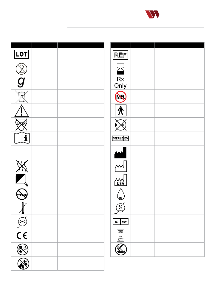
GLOSSARY OF SYMBOLS
The following symbols may appear on components or in information rel ated to the Quantum device.
™
Symbol Reference Title/Meaning
ISO -2492
SO 7000-1051 Do Not Reuse
I
ISO 7000-3832 Gravit y type
EN 50419
ISO 7000-043A Caution
ISO 15223 –
5.4.5
ISO 700 0-1641 Operating Instructions; eIFU
ISO 7010-M002 Follow Instructions for Use
ISO 7000-2724 Non-pyrogenic
ISO 7000-3079 Open he re
2
STERILIZE
ISO 7000-2608 Do n ot reste rilize
ISO 7000-0632
ISO 7000-2621
MDD
93/42/EEC
IEC 60086 -4
IEC 60086 -4
Batch Co de/
Manufacturer’s Lot
WEEE whee led bin
Recyle electronic equ ipmen t;
Do Not Throw in Trash
Not made w ith natu ral rub ber
Temperature limit s; Limi ts for
limit ation; R ange wh ich devi ce
latex
safe device exposure
Atmospheric pressure
can be safely exposed
CE Marks
Signies European technical
conformity
DO NOT disassem ble
(batte ry)
Do NOT inci nerate
(batte ry)
Symbol Reference Title/Meaning
20
EC REP
ISO 7000-
2493
ISO 7000-
2607
21 CFR Par t
801.109
ASTM F-2503
IEC 60417-
5333
BS EN 15986 -
4.2
ISO 7000-
2501
ISO 7000-
3082
ISO 7000-
2497
ISO 7000-
6049
ISO 7000-
2726
ISO 7000-
2620
BS/EN 1041
N/A
IEC 60086 -4
Catalogue Number
Use-by d ate;
Date afte r which the device is
not to be us ed
Caution: Fede ral (USA) law
restri cts this device to sale byor
on the ord er of a physi cian
MR Unsafe;
Device known to pose hazards in
all MR environme nts
Type BF Appli ed Par t
Non-DEHP
Does not contain the pht halate
plasticizer DEHP
Sterilized usin g ethylene oxide
Device Manufacturer
Date of manufacture
Country of manufacture
Numbe r of drops p er mlli litre
Humidity limitation;
Range wh ich me dical d evice can
be safely ex posed
Author ized repre sentative in the
European country
Global Trade Identicat ion
Numbe r; deno tes proximate UDI
barcode
Do NOT crus h
(batte ry)
-4-

TABLE OF CONTENTS
LIFEWARMER
Prescribing Information
Indications for Use .........................................................................................................................6
Warnings ..........................................................................................................................................6-7
Precautions ..........................................................................................................................................7
Intended Users & Use Environments ......................................................................................8
Quantum System Description
Device Description ........................................................................................................................9
Quantum System Components ..........................................................................................9
Quantum System Operation
Thermal Infusion Set (TIS) .................................................................................................... 10
Thermal Transfusion Set (TTS-B) ....................................................................................11
Charging/Connecting the Battery ................................................................................ 12
• Charging the Battery .................................................................................................... 12
• Checking Battery Charge Status ........................................................................ 12
• Connecting the Battery to the Controller ................................................... 12
• Important Battery Use Information .................................................................. 12
Connecting the Controller ....................................................................................................13
• Connecting the Controller to the TIS or TTS-B Tubing .....................13
• Disconnecting Components/Discontinuing Use ..................................13
Enabling/DIsabling Audible Alert System ...............................................................14
Instructions for Performing Manual Test of Audible Alert ...........................14
Sterility Status .........................................................................................................................................15
Sterile Components....................................................................................................................15
Single-Patient Use and Non-Sterile Reusable Components ...................15
Cleaning and Disinfecting ............................................................................................................15
Visual/Audio Indicators
User interface: Table of visual and audio indicators ................................ 16-17
Technical Specications ........................................................................................................18-19
Essential Performance .............................................................................................................18
System Information/Safety Classication ................................................................18
Performance .....................................................................................................................................18
Component Specications .................................................................................................. 19
Operating, Storage & Distribution Conditions ...........................................................20
EMC Compliance Statement .......................................................................................................21
APPENDIX ....................................................................................................................................................22
Troubleshooting Guide .................................................................................................. 22-23
Quantum Response by Temperature Table ...........................................................23
Glossary of Terms ....................................................................................................................... 24
Quantum Components List .........................................................................................24-25
Warranty .............................................................................................................................................26
™
-5-

PRESCRIBING INFORMATION
LIFEWARMER
INDICATIONS FOR USE:
The Qua ntum™ Bloo d & Fluid War ming System is ind icate d for warm ing blo od, blo od produ cts an d intrave nous
soluti ons pri or to administ ratio n in adult p atients. It i s intend ed for us e by healthcare professionals in hospital, c linical,
eld and t ransport environm ents to h elp preve nt hypothermia.
WARNINGS:
For the safe opera tion of the Quantum System,
•
all instructi ons, warnings and pre cautions
in this document must b e followed . Failure
to follow instructions fo r proper use may
result in d evice malfunction or injury.
Only the uid path and area s under protect ive
•
end cap s are STERILE. If end protectors
are not in place, DO NOT USE.
DO NOT pla ce tubin g sets or protect ive
•
end cap s in a sterile eld .
The TIS/ TTS -B is for S INGLE PATIENT USE ONLY.
•
DO NOT RES TERILIZE.
The Qua ntum Thermal Infusio n Set (T IS) IS NOT
•
for stan dalon e use with blood or blood product s.
A RED LED stro be and sustai ned audible ale rt on the
•
batter y indicates a ui d over-temperature condit ion
which can result i n hemolysis of blo od and e levatio n
of touch te mpera ture of the t hermal tubin g.
The over-temperatu re Audib le Alert System
•
may be man ually disable d. Ensu re that the
Audible Alert Sys tem is alway s enabled
unless a t actical haz ard is posed.
Repla ce Quan tum Transfu sion ( TTS-B) and I nfusi on
•
Sets ( TIS) in accordan ce with CURRENT A ABB/
CDC guidelin es and/or institutional p rotocol s.
All IV ui d bags mu st be vented of air p er IV ui d
•
manufa cturer s’ direct ions prior to co nnect ing to tub ing
set. Ca re must b e taken to e nsure th ere is not sucient
air in the uid bag and lin es to cau se an air e mbolism.
DO NOT ax, p lace or bind th e therm al (heated)
•
portion of the thermal tubin g directly to a patient.
It is recommend ed that t he Cont roller, Bat tery, and
•
Charger be surfaced cleaned and dis infecte d after
each pat ient us e following the instruc tions i n this
manual or accord ing to st andard insti tution al protocol.
DO NOT touch the Bat tery pins and
•
the pati ent at th e same time.
Warning: Use of thi s equipment ad jacen t to or
•
stacke d with other equ ipment shoul d be avoide d
ecaus e it could re sult in imprope r operation . If
b
such use i s necessar y, this equ ipmen t and the o ther
equipment should be observed to verif y that they are
operating normally.
-6-
The Qua ntum Syste m (including Therma l
•
Tubing TIS an d TTS-B) is MR UNSAFE .
The Qua ntum is in tende d for gravity admi nistration .
•
However, performan ce testi ng has b een
conduc ted in accordance with IS O 1135 -5 for
single u se tran sfusi on set s with pre ssure in fusio n
and foun d to be mec hanic ally st able. Th us,
the clinician may apply re asonable pres sure
to the infusate ba g if it is determin ed that
increa sed ui d ow is clinical ly indicated.
DO NOT attempt to use t he Quantum Syste m
•
components , inclu ding tubing sets (TI S,
TTS- B), Controller, Battery, or Charger wi th
uid war ming devices/component s from oth er
manufa cturer s. They a re not com patible.
DO NOT attempt to use chargin g device s, power
•
cables o r component s from oth er manu facturers
with the Quantu m System co mponents. They
are not com patib le and pose a safet y hazard.
DO NOT attempt to sterilize, au toclave
•
or submerge the C ontrol ler, Batte ry, or
Cha rger. Surface clean/disinfect only.
There are n o user-se rviceable parts i nclud ing the
•
Batter y. For all matters concernin g funct ionality
and ser vice, contact Life Warme r, Inc.
DO NOT attempt to ope n or access the
•
Controller, Batte ry, or Charger. Doin g so may
damage the components and /or result in
device ma lfunc tion, f ailure o r injur y.
DO NOT attempt to mod ify any c ompon ent
•
of the Quantum System. There may be NO
changes or mod icat ions to t he mech anics,
electronics , and/or sof tware of t he syste m.
DO NOT operate or store Quan tum comp onent s
•
outsi de of the speci ed environmen tal
limit s. A safety haza rd may occu r.
DO NOT use a mu ltiple s ocket ou tlet or ex tension
•
cord with a ny Quantum comp onent .
Degra datio n of sensors can re sult in inaccur ate
•
temperature rea dings a nd subs equent
outow temperatures. I f this oc curs, t he
Controller will indic ate a System Error.
™

PRESCRIBING INFORMATION (continued)
WARNINGS: (continued)
Use of acce ssori es, tr ansdu cers an d cables other than
•
those speci ed or provided by th e manuf acture r of this
equipment could result i n increased electrom agnet ic
emiss ions or d ecreased ele ctroma gneti c immun ity of
this eq uipme nt and res ult in improper o perat ion.
PRECAUTIONS:
Examine all sys tem com ponents for da mage, we ar,
•
and function ality p rior to u se. If any compon ent
appea rs fault y, damage d or defective, DO N OT USE.
Inspe ct all ca sings, component s and
•
enclos ures for da mage, cracks , breaks, or
loss of integrit y. If any of these are obs erved,
do not use a nd repl ace com ponent.
Exceeding rec ommended ow rates and /
•
or low ambi ent temperatu re may result
in lower out put temp eratu re.
Some dr ugs or dr ug preparatio ns may be sensitive
•
to warming. As with any ui d or bloo d warmi ng
system, carefu lly review th e drug manufac turers’
literature for info rmati on abou t therm al sensitivi ty.
Do not positio n the devi ce in a man ner tha t
•
makes it dicult to view or di sconn ect the
Controller and /or change the Batte ry.
When th e useful life of the lithium Batte ry
•
has bee n reached, it sh ould be dispos ed of
separ ately in accordance with na tiona l and
local co des. C ontac t your loc al enviro nment
control o r dispo sal agency for f urth er deta ils.
Used, single-use compone nts (TIS, T TS-B)
•
should b e disposed of in a ccorda nce with
local , national and /or international biohaz ard
protocols by the a ppropr iate personnel.
Porta ble RF communi catio ns equipment (including
•
peripheral s such as antenna c ables and external
antennas) shou ld be use d no closer than 30
cm (12 in ches) to any part of the Qua ntum Fluid
Warming Sys tem, in cluding cables spec ied by
the manufactu rer. Other wise, degradation of t he
performance of the equipme nt could re sult.
The Cont roller a nd Battery are not
•
intended for patient contact .
Although the Quantum has been tested to
•
insure it w ill sur vive a drop of 1 meter (3.28 ft),
care sho uld be ta ken that t he system is not
droppe d to reduce the pote ntial of damage.
It is recommend ed prop er Battery an d
•
Controller per formance be veri ed
before each use of th e Quantum.
Fully charg e new batteries u pon receipt and
•
prior to u se or sto rage to ex tend batter y life.
Check B atter y charge status p rior to e ach use to
•
ensure adequate charge fo r device o perat ion.
It is recommend ed that t he Battery be f ully
•
charge d before in itiating warming.
It is recommend ed that t he Battery
•
be charg ed afte r each us e.
The Battery Ch arger must be co nnected
•
to an ear thed mains socket outlet.
The Cont roller J acket should be replace d after every
•
10 uses (approximate) or six mo nths (whichever
occurs rst) o r at anytime the C ontrol ler Jacke t
appears damaged, loose-tting, or compromised.
LIFEWARMER
™
-7-

INTENDED USERS &
LIFEWARMER
USE ENVIRONMENTS
Intended Users:
Opera tors of th e Quantum should be knowledgeable in th e use of IV administration set s for infu sion of uids an d
transfusio n of blood /bloo d produc ts. The Quantum the rmal tub ing set s (TIS and TTS-B) deliver IV soluti ons and
blood/blood p roduct s in a similar man ner as co nventional IV in fusio n and tra nsfusion sets.The Qu antum is d esigned for
quick set up and de ployme nt usin g minim al steps. Inten ded users include mil itar y medi cs, EMS P aramedics , regis tered
nurses, physicians and mid- level practitioners . Patie nt-users of the Quantum i nclude any adult p atient presenting with
the nee d for IV solution s, bloo d or bloo d produc ts who m ay bene t from war med ui ds..
Intended Use Environments:
The Qua ntum Blo od & Flui d Warming System is transporta ble. The intended use env ironments in clude hospit als (e.g .,
in-pat ient /full service s facil ities), clinical environmen ts (e.g., satellite emergenc y center s, outp atien t center s, etc.),
and eld e nvironments (e .g., po int of inj ury in cludi ng civilian an d battle eld locations) and tr ansport environme nts
such as emergen cy vehicles en rou te (i.e., xed and rotary wing aircraft a nd ground and ai r ambul ance). The Quan tum
Controller, Batte ry, TIS/TTS- B are inte nded for u se in the Patien t Environment. N ote: The B atter y Charg er shou ld only
be used i n hospi tal and protecte d xed structure environ ment s.
QUANTUM SYSTEM DESCRIPTION:
Device Description:
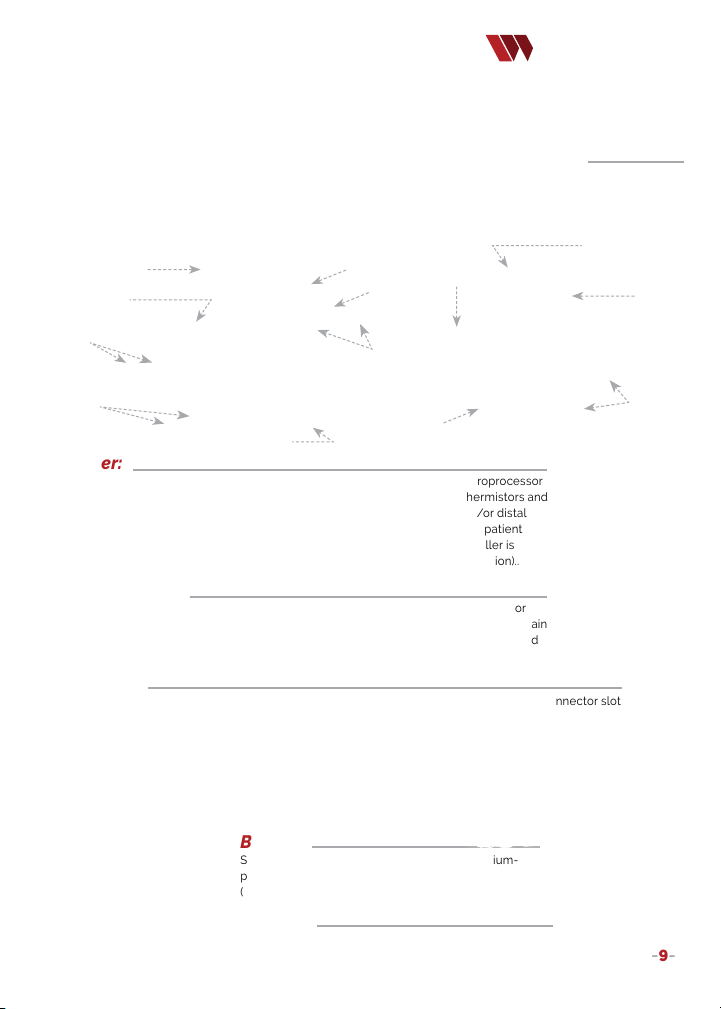
The Qua ntum Blo od & Flui d Warming System is a lightwe ight, b atter y powered, high ly port able, u id warm ing sys tem
in which t he warm ing ele ment is i ntegra ted with s peci ally designed i ntravascula r admin istra tion tubing. Fluid war ming
is achieved in the tubing t hrough t he use of p roprie tary therm oplastic po lyureth ane and a s oftw are control .alg orithm.
The Qua ntum IV ad minis trati on
tubing i s double-ex trude d to yield a
congu ratio n that ha s both an i nner
tubing l ayer and a n outer tu bing
layer. A conductive heating e lemen t
is betwe en the t wo layers b ut does
not come i n conta ct with the uid
path [Fi gure 1]. T he outer tubing layer
acts as a n insul ator while the in ner
tubing l ayer tra nsfers t he heat f rom
the heating ele ment to the uid path.
The Qua ntum Syste m, fully c harge d,
is able to wa rm and maintain up to
2 units ( 9 00mL +/- 100mL) of cold
(4ºC) bloo d produc ts or IV solutio ns to a pre-set temperatu re of 38ºC ± 2 ºC (100.4ºF ± 2) at a ow rate of 100 mL/min
(depen ding on t he ambient tem perature). Or, approximately 1700 mL of 20ºC IV solution to a set p oint of 38ºC +/- 2ºC
at a ow rate of 20 0 mL/min . Eective w armin g ow rates range fro m 2 to 200 mL /minute de pending on input uid
temperature and ambient conditions.
Thermistors located in the tub ing con tinually meas ure temp erature a nd provide that in put to the Controller. The
Controller ass esses the temp eratu re input a nd regul ates the amount of e nergy a pplied to the heating e lemen t needed
to reach an d maint ain a con stant uid temperatu re. The monitor ing and i ndependent appli catio n of energy (heat ) along
the uid path allows the Qu antum to respond to varyi ng temp erature input s from the uid sou rce to nea r the point of
patient entr y to ensure uid tem perature is ≥ 36ºC to < 44ºC at deliver y.
The Qua ntum is powered by a rechargea ble lit hium- polymer batte ry. The co mplete Q uantum B lood & Fluid Warmi ng
System, includi ng the B atter y, weighs less than 1 ,5 lbs. a nd can t ravel wit h the pat ient ac ross multiple cl inical use
environments w hile maintaining opt imum u id temp erature.
Binding layer securing
the heating element
In n er tub in g (cond uc t s
-8-
Outer tubing
Heating element
sterile uid pat h and
absorbs heat)
Figure 1:
Quantum Tubing
C
ross Section
™
QUANTUM SYSTEM COMPONENTS:
The Qua ntum Blo od & Flui d Warming System con sist s of sterile ther mal
IV tubin g (TT S-B or TIS), a Controller (i ncluding Jacket), Bat tery, and B atter y Charger..
LIFEWARMER
TUBING SETS:
Thermal Transfusion Set -Blood (TTS-B) | Thermal Infusion Set (TIS)
Intrava scula r admin istration sets for infusio n (TIS) o f IV uid s and tra nsfus ion (TTS- B) of bloo d/blo od products an d IV
uids . The set s are ass emble d and con sist of L ife Warmer’s proprietary the rmopl asti c tubin g with integrate d coppe rnickel heating elements, tempera ture sensing th ermis tors, a nd sta ndard IV a dmini strat ion com ponents (se e Figure s 2
and 3). The TIS and T TS-B connec t to the Controlle r via the c ircuit c artr idge co nnector. The TIS and TTS -B are prov ided
sterile, for sing le-pa tient u se only.
00 micron ltered
2
drip chamber
Circuit cartridge
connector
RED Roller
Clamps
“Y” t ype
dual spikes
Figure 2:
TTS-B Thermal
Transfusion Set -
BLOOD
M
ale Luer
Connector
R
ED Downstream
Roller Clamp
Clamps
Injection
lide
S
Ports
chamber
2
M
ale Luer
Connector
ip
Dr
0 gtt/ml
Figure 3:
Thermal Infusion
et - IV FLUIDS
S
Controller:
The Cont roller i s the com mand ce nter of th e Quant um System . It cont ains th e microprocessor
and cont rol algorithm that continually a sses ses temperatu re input from tubing thermistors and
regula tes the energy prov ided to t he tubing heating elements i n the proximal and/or distal
segme nts to rea ch and ma intai n tempe rature between 3 8ºC ± 2ºC / 100.4ºF ± 2) at patient
delivery. The Co ntrolle r receives power wh en conn ected to the Bat tery. The Controller is
reusab le. Sur face clean/disinfe ct only. (Co ntrolle r does not suppo rt/req uire ste riliza tion)..
B
LUE Rolle r Clamp
TIS
& Slid e clamps
Controller
cartridge
connector
njection
I
Ports
in jacket
Circuit
Controller Jacket:
The Cont roller c omes t ted with a Jacket th at perm its th e mating (conne ction) of the TIS o r
TTS- B tubin g circuit conne ctor to th e conne ctor slot on the Co ntrolle r. The Jacket must rem ain
in place for device operation. T he Jacke t also p rotect s the Controlle r and sho uld be rep laced
after approxim ately 10 uses or 6 months.
Cleaning Kit:
Kit cont ains hydrophob ic coating pack, extr a Contro ller Jacket, an d cleani ng brush for Jacket conne ctor slot.
™
B
attery C harger
Battery:
Suppl ies power to the Controller. Batter y is lith ium-
polymer and rech argea ble. Sur face clean/disinfe ct only.
(Batte ry doe s not sup port /req uire ste riliza tion).
Charger:
For charging the Q uantum Battery. AC-powere d reusa ble
component. S urfa ce clean /disinfect o nly. (Charge r does
not supp ort /require sterilization ).
Batter y
-9-

QUANTUM OPERATION:
To begin usin g the Qu antum Blood & Fluid Warmin g System, s elect t he
approp riate tub ing set fo r infus ion of IV solutio ns (TI S) or tra nsfus ion of blo od/blood products o r IV solutions ( TTS -B).
F
ollow the d irections on p age 9 for ei ther the TIS or T TS-B tubing se lected .
THERMAL INFUSION SET (TIS) –
For Infusion of IV Solutions
Standard spike w ith vent
•
15 micron part icle lte r
•
•
•
WARNING:
TIS IS NOT for s tand alone use with blood products .
Only uid path and area und er protective end caps are S TERILE.
Luer act ivated i nject ion sites
Male Luer lock ada pter
•
•
LIFEWARMER
Tubing length: 80” (230 cm) long
Primin g volume: 16 mL
TIS USE: (Use Aseptic Technique):
1. Open po uch whe re indi cated . Remove tubing set
and clos e roller cl amp. DO NOT place tu bing, o r
protect ive end caps in ste rile eld.
2. Remove Sp ike protector end c ap. Insert spike into
the uid contai ner. Note: ke ep vent cap close d
unless i nfusing from a rigid solution co ntain er.
3. Fill the d rip chamber by sq ueezin g the dri p
chamber until a pproximately half full .
4. Remove pro tector e nd cap from male Lu er adapter.
5. Slowly op en rolle r clamp to prime tubing a nd purge
air. Invert a nd tap inject ion ports wh ile prim ing. O nce
prime d, close ro ller cl amp.
6. Attach ad apter to vascul ar access device. Twist to secu re
Luer lock conne ction .
7. Slowly open ro ller clamp and a djust fo r desired ow rate.
Luer Activated Injection Site:
Use only st anda rd Luer connect ion devi ces. D O NOT USE ne edles or blunt cannul as to acce ss the swabable valves.
sing a ste rile alcohol pa d, swab t he Luer activate d surf ace and let it air dr y. C arefully connect the syringe o r Luer
U
connector STR AIGHT into the valve in a clock wise t wisting moti on. To disco nnect, twis t counte r clock wise. Flush th e
Luer act ivated s ite afte r each us e per facilit y protoco l.
To Initiate Fluid Warming:
1. Completely prime the syste m followin g the ste ps above, p urging all air
from the l ine, and star t infusion at desired ow rate. (Note : 7 mL/minute
minimum ow rate is n eede d to initiate warm ing. O nce warming be gins
(Flashing Blue LED), User may titrate to lower ow rates if des ired.
2. Briey pres s the ‘Status’ button on the Batte ry to ch eck bat tery
charge. Three gre en LEDs i ndicate a full ch arge. One LED or
no LEDs in dicate insucient ch arge to op erate the device. If
the Bat tery has sucient cha rge, rem ove the prote ctive cove r
and connect th e Contro ller to th e Batte ry. A green blinking
Controller LED in dicates syste m is ready fo r use. (I mage 1 )
3. Connect t he Cont roller to t he circu it car tridge
of the TIS by re moving its red protecti ve cap
exposi ng the ci rcuit ca rtri dge. (I mage 2)
4. Co nnect the Controller to the tubing by rmly
pressi ng the tubing’s ci rcuit cartridge into the
connector slot o n the Controlle r (Imag e 3). A
Blue a shing L ED indicates th e uid is w armin g
but is <36º C. A sol id green LED indi cates u id is
≥36ºC and < 44ºC. At steady state, the System
strives to maint ain infusion at a s et poin t of
38ºC +/- 2ºC. (Image 4) Note: th e System will
attain set point only dur ing owing infus ion.
5. D epending on uid temp eratu re and ow rate, the
User may need to adjust th e infusion rate to s tay in th e set poi nt rang e.
6. Whe n infusion is complete, disconnect th e Contro ller
from the TIS and battery to conserve power.
Image 4
Image 1
Image 2
-10-
Status Button
Circuit cartridge
Image 3
™

THERMAL TRANFUSION SET (TTS-B) –
for Blood/Blood Products and IV Solutions
Dual spike/one vent
•
200 micro n lter
•
WARNING: Only uid path an d area under prote ctive en d caps are STERIL E.
Luer act ivated i nject ion sites (2)
•
Male Luer lock ada pter
•
•
•
LIFEWARMER
Tubing length: 80” (230 cm) long
Primin g volume: 22 mL
TTS-B USE: (Use Aseptic Technique)
1. Open po uch whe re indi cated . Remove th e
tubing s et and clo se all th ree rolle r clam ps.
IMPORTANT: Only uid path is sterile.
DO NOT pla ce tubin g, or protective end caps i n
sterile eld.
2. Remove Sp ike protector end c ap. Insert one
spike into the uid container, open roller cl amp
under uid cont ainer. Note: keep ve nt cap
closed u nless infusin g from a rig id cont ainer.
3. Invertlte rchamb er. Partia lly open roller
clamp d ownstre am of lte r chamb er. Allow
approxi mately ½ of ch ambe r to ll wit h uid.
Close downstrea m (regul ating ) roller clamp.
Luer Activated Injection Site:
Use only st anda rd Luer connect ion devi ces. D O NOT USE ne edles or blunt cannul as to acce ss the swabable valves.
U
sing a ste rile alcohol pa d, swab t he Luer activate d surf ace and let it air dr y. C arefully connect the syringe o r Luer
connector STR AIGHT into the valve in a clock wise t wisting moti on. To disco nnect, twis t counte r clock wise. Flush th e
Luer act ivated s ite afte r each us e per facilit y protoco l.
4. Part ially op en rolle r clamp o n unused lead, prime and
close this roller clamp .
5. Return lter cha mber to u prigh t posit ion and tap to
displ ace air t rappe d in lter. Slowly open d ownstream
roller cl amp to pr ime, purge air an d ll tub ing. Invert and
tap injectio n ports while uid is ow ing. En sure air i s
expelled, repeat prim e if nece ssar y.
6. Attach ad apter to vascul ar access device, twist to secure
Luer lock conne ction .
7. Slowly open ro ller clamp and a djust fo r desired ow rate.
To administer blood, atta ch blood contai ner to un used
lead. Close rolle r clamp under s olution conta iner. Open
roller cl amp under blood conta iner..
To Initiate Fluid Warming:
Status Button
Image 1
Circuit cartridge
Image 2
Image 3
1. Complete ly prime t he system followi ng the steps above, purgin g all air
from the l ine, and star t infusion at desired ow rate. (Note : 7 mL/minute
minimum ow rate is n eede d to initiate warm ing. O nce warming be gins
(Flashing Blue LED), use r may titr ate to lower ow rates if desired.
2. Briey pre ss the ‘Status’ b utton on t he Battery to check battery charge.
Three gre en LEDs indicate a full ch arge. One LED or no L EDs indicate
insucient ch arge to op erate the device. If the Batter y has su cient
charge, remove the p rotective cover and conne ct the Co ntrolle r to the
Batter y. A green bli nking c ontroller LED indicate s system i s ready for use.
(Image 1).
3. Connec t the Con troller to the circ uit car tridge of the
TTS- B by removing its re d protective cap ex posin g the
circuit c artridge. (Image 2).
4. C onnect the Co ntrolle r to the tub ing by rmly press ing
the tubi ng’s circuit car tridge into the connec tor slot on
the Controller ( Image 3). A Blue ashing LED i ndicates
the uid is warmi ng but is < 3 6ºC. A solid gre en LED
indic ates ui d is between ≥36º C and < 44º C. At ste ady
state, system st rives to ma intai n infus ion at a set p oint
of 38ºC +/- 2ºC. (Ima ge 4) Note: t he System w ill att ain
set point only during owin g infus ion.
5. Dependi ng on ui d tempe rature and ow rate, t he
User may need to adjust infusion rate to stay in the
temperature set point ra nge.
6. When infusi on is comple te, disconnect the Controller from TTS-B.
Image 4
-11-
™

CHARGING/CONNECTING THE BATTERY
STEP1: Charging the Battery
Plug the Charger i nto an AC wall outlet us ing the AC power cord provided .
•
The Charger is powe red from 100 to 264 Vac, 50/60 Hz
Conne ct the Batter y to the Charger as s hown.
•
A solid green LED on the Charger ind icates ready for u se. A ashing blue
•
LED on the Charger i ndicates battery ch arging failure a nd the b atter y
should b e removed /replace d.
Charge s tatus progress ion is di splaye d by green L EDs on the batter y. Th is
•
may be del ayed whe n batter y is warm and will initiate automatical ly once
the battery temp is safe to c harge. When fully charg ed, the batter y enters
sleep mode and the LEDs turn o.
Allow the B atter y to charg e for 90 min utes (if f ully discharge d).
•
STEP2:Checking Battery Charge Status
Verify th e charge status o f the Bat tery by b riey pre ssing the Status
button a nd obse rvin g the LED in dicators:
1 LED illum inated: Batte ry cha rge is “Low”. Batter y has insucie nt
•
charge to o perate the devi ce. Charge or repl ace the Batter y.
2 LEDs Illu minate d: Battery is approximately 50% c harge d.
•
All 3 LEDs il lumin ated: Batter y is fully charged . Allow th e Batte ry
•
to charge fo r 90 minu tes (if fully discharged ).
Note: Bat tery c harge status sh ould be checked prior to e ach use.
STEP3:Connecting the Battery to the Controller (if preparing to warm uids)
Remove the protect ive cover fro m the Bat tery.
•
Conne ct the Controller to the Batter y by inserting the barrel conn ector end.
•
Upon connect ion, al l three (3) B atter y RED LEDs w ill bli nk simu ltane ously with or wit hout an a udible tone
•
(depen ding on w hethe r the Audible Aler t Sys tem is en abled ) while th e Contro ller ini tiates i ts sta rt-up se quence
(i.e., LED ash sequen ce: blue, yellow, green).
A green, b linki ng LED indicate s the controller is ready for use
•
The Cont roller (w ith connecte d Battery) is now re ady for co nnect ion to th e TIS or T TS-B
•
Important Battery Use Information:
The Battery sh ould be FULLY charged o n receipt and pri or to eac h use.
•
Recharge the Ba tter y after e ach use – eve n if not fully discharged.
•
Repla ce the Battery if no gree n LEDs are illumin ated on status ch eck.
•
Conne ct to charger to troublesh oot.
•
A fully cha rged Battery should p rovide su cient power to wa rm two (2)
•
units of refrigerated b lood pro ducts or approx imately 1 .0 L of intrave nous
soluti on or at a ow rate of 100 mL/minute (ba sed on a uid input
temperature of 4º C (38ºF).
The waterproof vent on the bottom of the Batte ry is important to ma intai ning protecti on from mo isture a nd
•
particles. Before us e, ensure the vent is intact. If the ve nt is worn , frayed, o r not securely att ache d,
-12-
obtain a new Battery).
LIFEWARMER
Vent
™

CONNECTING THE CONTROLLER
Connecting the Controller to the TIS or TTS-B tubing
Circuit cartridge
LIFEWARMER
™
Step 1
STEP1:
the middle conn ector of t he tubi ng set to expose
t
STEP2: Firmly press th e circui t cart ridge o n
the tubi ng into th e conne ctor slot on the bl ack
Controller Jacket as shown in the ph oto..
Remove the red protective ca p from
he circuit cartridge. Disc ard the re d protec tive cap .
Step 2
STEP3:
Refer to Controlle r LED illuminati on for System status.
A
ashing Blue LED that increases in intensity and
speed i ndic ates the uid is wa rming b ut is <36ºC.
A solid green LED indica tes the u id is bet ween ≥36ºC
and < 44ºC.
One gree n LED ash every s econd (w hile connecte d
to tubing) indicates st and by mo de, no ow or uid
ow is too slow to warm.
A solid ye llow LED indicate s a low batte ry con dition.
A yellow strobe LED in dicates a dry l ine, po or
connection , disconnect ion or tu bing me chanical
failure.
Disconnecting Components /Discontinuing Use
When infusion is complete, disconne ct the Co ntroller from the tubing.
•
Disconnect t he Cont roller from the Ba tter y.
•
Dispo se of cont aminated bio hazard materials acc ording to CDC and i nstitutional Guid elines.
•
Surface clean/disinfect Controller, Batte ry, and Charger.
•
Conne ct Battery to Ch arger and allow to charge for 9 0 minute s for a fully d eplete d battery.
•
-13-

ENABLING/DISABLING AUDIBLE ALERT SYSTEM
The Qua ntum Blo od & Flui d Warming System is equipp ed with a v isual a nd Audible Aler t system in the event of an
over-tempe rature co nditi on. An ove r-temper ature con ditio n can res ult in hemolysis to blood and/or elevated touch
temperature of th e intrav ascul ar tubi ng. Quantum Systems are provided w ith thi s feature fu lly enab led.
However, the Aud ible Ale rt Syste m may pose a h azard to certa in mili tary and/or tact ical m edic al user s depen ding
on the use environ ment. For these users a nd use cases only, if the prese nce of th e audib le alert presents a
potential hazard, it may b e disabled by following th e instructions below.
LIFEWARMER
Disabling Audible Alert System
1. Press and hold the Status button on t he Battery
continuously for 15 seco nds unt il hear ing 3 beeps and
seein g three ashes of the Red L EDs.
2. The Audi ble Aler t System i s now deac tivate d.
The audible alert self c heck to ne on com ponent
connection a nd in the event of an over-te mpera ture
condit ion is now silenc ed unti l user re -ena bles. (Note:
the visu al over-temp erature alert ( Red LED st robe)
remains active.
Re-enabling/Self Check
of the Audible Alert System
1. Press and hold the Status button co ntinuo usly for 15 secon ds until h earing the audible alert be ep 1 time and the 3
LEDs bli nk once.
2. The Audi ble Aler t System i s now react ivated .
3. The audible self-check tone wil l now be active when the cont roller i s conne cted to th e batte ry.
It is stro ngly reco mmended that the (over-temperatu re) Audib le Alert System rem ain ena bled un less a ta ctical hazard
is pose d. Re- enable the Aud ible Alert System followin g the ste ps above as soon as p ossible afte r the tactica l hazard i s
no longe r prese nt.
™
-14-

STER ILIT Y STATUS
LIFEWARMER
Sterile Components
Only the uid path and area u nder th e protec tive end c aps of th e TIS and T TS-B tubing sets are STERILE. Sterilizatio n
is achieved by exposure to Ethylene Oxi de (EO). Note: the prote ctive en d caps on the tubing set s should ONLY be
removed im medi ately pri or to tubi ng use. D O NOT place tube sets or protective e nd caps in the ste rile eld.
Product m ust be s tored in t he orig inal un opened packaging where temperatu res are between -20ºC to 60ºC . Ver ify th e
‘Use By ’ date on th e packaging. I f it is pas t the ‘U se By’ date, DO NOT USE .
Single [Patient] Use Components
The Qua ntum TIS ( Thermal Infusion Set) and T TS-B (Therm al Transfu sion Se t – Blood ) are disposab le, for Single Patient
Use Only. Do not reprocess or res terilize.
Non-Sterile/Reusable Components
The Cont roller w ith Jacket, Bat tery and Charg er are reusable and are provi ded non-sterile. These components do
not supp ort sterilization, but ins tead sh ould be surfac e cleaned/disinfe cted af ter eac h patie nt use according to the
instructions contained i n this ma nual.
CLEANING AND DISINFECTING
Cleaning and Disinfecting Instructions
The Qua ntum Controlle r with Jacket, Battery, and Charge r are supplied n on-sterile and should be sur face cle aned/
disinfe cted af ter each patie nt use.
Before cle aning , disco nnect the Controller f rom the Batter y. Remove the B atter y from the Charger a nd/or unplu g the
Charger from AC power. (Failure to do so before init iatin g cleani ng may exp ose per sonnel to unsa fe condi tions a nd
result in d amage to the devi ce). Note: th e followi ng proce dures are not guarantee d to contro l the spread of pat hogens.
Consult the loc al hosp ital in fection contro l admin istrator rega rding cleanin g procedure pol icies at your ins tituti on..
Cleaning
After each use, clean all exteri or sur faces of t he Cont roller (w ith Jacket in pla ce), Batte ry, and Charger, with a s oft
cloth moistened with a mild detergent solution . Remove any residu al clean er from the component surfac es. Dr y all
component sur faces. As Nee ded: the Controller Ja cket Con necto r Slot may be cleane d using the bru sh provid ed in
the Clea ning Ki t.
™
Disinfecting
After each use, d isinfe ct all ex terior surfaces of th e reusa ble comp onent s, i.e., Controller wit h Jacket , Battery, and
Charger, with a low-level disinfe ctant (suci ent for normal us e condi tions) with one of the following: 70 -90% Ethyl or
Isopro pyl Alcohol, Sodium Hyp ochlo rite (5.25 -6.15% house hold ble ach diluted 1:500). or comm ercial medic al-gr ade
wipe (e.g ., Kim-Wipe). Dr y all com ponent surf aces.
Controller Cleaning/Jacket Replacement
After the Controller is u sed approximately 10 times (or six mo nths), rem ove the Jac ket and cle an the entire Controlle r,
includ ing the i nside o f the Circuit Car tridge, with 70-90% Ethyl or I sopropy l Alcoho l. Let dr y 2 minutes. Usin g Quant um
Cleaning Kit, reapply Hydropho bic Coating to the Circui t Cartridg e and ins tall a new Jacket . Note: On ce a Jacket h as
been removed, it s hould b e discarded an d repla ced wit h a new Jacke t.
When us ing in conditi ons of excessive mo isture (e .g., e ld use/rain, etc.), rea pply hydrophobi c coating and rep lace th e
Jacket af ter eac h use. (Note: do not re use Jac kets. If the Jac ket is removed, it mu st be rep laced with a new Jacket to
ensure proper t ).
Note: Do not use caustic o r abrasive clea ners or s trong solvents .
-15-

VISUAL/AUDIO INDICATORS
The Life Warmer Quantum Blood & Flui d Warming System is d esign ed for simple, rel iable operation.
Refer to the Visual/Audio Ind icators Legend prese nted be low.
LIFEWARMER
USER INTERFACE VISUAL/AUDIO LEGEND
Quantum Controller
LED INDICATOR MEANING(S) ACTION REQUIRED
Start-Up Sequence
Blue
Yel low
Flash
Flash
Green Fl ash - ever y 4 seconds
when NOT Connected to Tubing
Green Fl ash - ever y second
when Connected to Tubing
Blue Flashing RAMP UP
(Flashing LED with increasin g
ntensity/speed)
i
Yellow Solid Low battery condition Charge or replace Batte ry Pac k
Green
Flash
Green S olid
Clear
Flash
Controller initializing
Self-Check OK
Ready for U se
Controller connecte d to
tubing a nd ready for ow.
(Stand by Mode).
ow too slow to wa rm
Fluid is warming and/or
temperature (<36º C)
Fluid is warmed to
≥36ºC (in s teady s tate).
sequence
No ow or
NORMAL
Consi der redu cing ow r ate if clinical ly accept able.
Conditions
No action requi red.
Conne ct Cont roller to p rimed tubing s et
Increas e ow rate if warming is desired.
If no fur ther wa rming desired, disc onnect system
Flow rate may b e exceed ing heating ca pacit y.
Check tu bing for p ossible contact
with cold surfa ce outdo ors.
No action requi red
Refer to Qu antum Sys tem Resp onse
by Temperature Table in Appe ndix.
™
Quantum Controller
LED INDICATOR MEANING(S) ACTION REQUIRED
Poor connection
Intentional disconnection
Tube mechanical failure.
Remind er to reat tach to
*
tubing s et if fur ther
warmin g is desi red.
Poor con nection to Bat tery,
Batter y Dead or
Controller failure
Yellow – Flash ing
(3 ashes – 1 every h alf
econd)
s
NO LEDS
Dry li ne
ALERT
Conditions
Disconnect C ontrol ler from tu bing set, ensure tubin g
set is com pletely primed a nd no air i n line.
If prope rly primed, reat tach the Controller to the
tubing se t and the ye llow stro be should stop.
If yellow st robe pe rsist s, tubing set may have a
*
mecha nical f ailure . Disco nnect Controller and t ubing
from pati ent. O btain a n ew Quantum Tubing Set,
follow Quick Start to pri me and at tach to p atient.
Disconnect C ontrol ler from B atter y to conserve
batter y power if no furth er warm ing is de sired .
Check ch arge st atus of Batter y.
If conne ction is prope r and Battery is charg ed,
-16-
Check co nnection to Batter y.
replac e the Controller.

VISUAL/AUDIO INDICATORS
LIFEWARMER
USER INTERFACE VISUAL/AUDIO LEGEND (continued)
Quantum Battery Pack
LED INDICATOR MEANING(S) ACTION REQUIRED
Red –STROBE and/or
AUDIBLE ALERT
(Sustained)
3 Red LEDs ash
simultaneously during
Start-Up and Audible Ale rt
Military and Tactical Medicine users: If the pre sence of an audi ble aler t presents a hazard, it may b e deact ivated by
the use r. Press and hold the status bu tton con tinuo usly for 15 s econd s until h earin g three quick be eps and seein g
three ashes of the Red LEDs, the a udible alert i s now dis abled . To reactivate, press an d hold th e status button a gain
for 15 sec onds until one b eep occ urs and t he Red LEDs ash once.
FLUID OVE R
TEMPERATURE
Audible Alert
is enabled
ALERT
Conditions
Stop uid ow. Discon nect Controller
from Battery and from tub ing set ..
C
heck inf usion soluti on cont ainer a nd line.
If solution cont aine r does no t feel war m to the tou ch,
reapply (reconn ect) t he Quantum Syste m.
N
ote: If aud ible ale rt is di sable d,
then only RED LED will strobe.
The Red B atter y LEDs an d Audible Alert w ill activate bri ey
each tim e the Co ntrolle r is conn ected to the Bat tery in the
normal condit ion wit h a charged batte ry as a functi onal tes t.
If NO LEDs , the Bat tery m ay be out of charge or
malfunctioning.
™
Quantum Battery Pack
LED INDICATOR MEANING(S) ACTION REQUIRED
Green S olid
(Battery Status)
reen LED – Batter y
1 G
Low (insucient to
operate device)
2 Green LEDs – 50%
charged (approximate)
3 Green LEDs –
Fully charg ed
NORMAL
Conditions
Sucient to power device, b ut recom mend
Quantum Charger Conditions
LED INDICATOR MEANING(S) ACTION REQUIRED
Contin ue charg ing unt il Battery st atus indicate s fully
charge d (three LEDs illuminated). A fully de pleted B atter y
require s 90 minutes to fully c harge
Disconnect B atter y from Charger, wait 5 se conds
f condit ion pe rsist s, obt ain a new B atter y.
I
Green S olid Normal Charging
Blue - Flashing B atter y charging failure
Charge or replace Batte ry
charging until f ully cha rged
o action require d
N
and reco nnect to Charge r.
-17-

TECHNICAL SPECIFICATIONS
The Qua ntum Blo od & Flui d Warming System has been tested an d found to co mply wit h recognized
stand ards for electrical sa fety and e lectro magnetic com patib ility. Th ese limits are d esigned to provide
reason able protectio n again st harmful inte rferences in cl inical use env ironme nts. T he System gener ates
radio frequen cy energy and sh ould be instal led and u sed in ac cordan ce with these in struc tions .
LIFEWARMER
Essential Performance:
The Ess entia l Performance of the Qu antum Blood & Fluid Warmin g System is to indic ate out ow uid temperature
when at or o utsi de the pre -set temperatu re range (≥ 36 to < 44ºC a t steady state) to the Operatoan d to detect proper
operational status.
Essential pe rform ance is conrmed by verif ying start-up L ED sequences of t he Battery an d Contro ller up on conn ection.
This con rmation sho uld be pe rform ed before each use of the Syste m. Upo n conne ction, all three (3) Battery RED L EDs
will blink simultaneously with or wit hout an a udible tone (dependi ng on whe ther th e Audib le Alert System is e nable d)
while th e Contro ller ini tiates i ts start-up sequen ce (i.e. , LED as h seque nce: blue, yellow, green,clear ).
System Information/Safety Classications:
BF Appl ied Part – TIS/ TTS -B Flui d Path
ME System .........................................................................................................................................Battery, Cont roller, TIS/ TTS-B, Cha rger
ME Equipment.................................................................................................................................B atter y, Controller, TIS/T TS-B
Type of protection aga inst electri cal sho ck ..........................................................Class 1 / inte rnally p owered
Degree of protection ag ainst e lectr ic shoc k ........................................................Type BF
Mode of Operation ......................................................................................................................Continuous
Performance (Warming):
Fluid Temperature Set Point ...............................................................................................38ºC ± 2ºC (100.4º F ± 2)
Fluid Warm ing Volum e* ..........................................................................................................Up to 1000 mL of bloo d products at 4ºC
uid input at a ow rate of 100mL /min
Up to 1700 mL of IV soluti ons at 20º C input a
a ow rate of 200 m L/min
Eective S et Point Warming Flow Rate* ..................................................................2 to 100 mL/minute 4º C uid input
2 to 200 mL/min 20ºC uid input
™
*Base d on fully c harged batter y and depending upon s tarting am bient te mper ature.
-18-

TECHNICAL SPECIFICATIONS
Component Specications:
Controller
PARAMETER VAL UE
Opera ting In put
Volt age (Vd c)
Input Volt age
Absolute Max (Vdc)
Opera ting Current (A) 0.001 minim um / 8.0 Max
Power interrupti on
tolerance (ms)
Charge Volt age (Ma x) 4.20V +/- 0.03V /cell
Charge Current (M ax) 1.6A
Liquid/Solid Ingress Controller wit h Jacket: IP 53
Weig ht 2.5 oz
Service (Use) L ife 1000 insertions/removals
PARAMETER VALU E
Sterility – Flui d path/
area underneath
protect ive end caps
Biocompatibility ISO 10993
Infusi on Set
Compatibility
Liquid/Solid Ingress
With protective c ap on
card connector
Weig ht:
Service (Use) L ife (Per) Single Patient Use
33.0 (min); 4 4.4 Typical ; 55.0 Max
56.0
30
TIS/TTS-B
Ethylene O xide
ISO 8536 -4
IP 53
≤ 60g (TI S)
≤ 75g (T TS-B)
LIFEWARMER
Battery
PARAMETER VALUE
Conguration 12 S1P / Li-Pol pouch cells (3.7v)
Chemical System Lithium
Nominal Voltage 44.4 V
Capacity
Conguration 12S1P
Discharge Current
(Max)
Discharge Cuto
Voltage
Charge Volt age (Ma x) 4.2 0V +/- 0.03V /cell
Charge Cu rrent (Ma x) 1.6A
Energy Rat ing 40.4 Wh
Liquid/Solid Ingress IP 67
Weig ht 16 0z
Service (Use) Li fe 3 years/500 cycles
Shelf-Life
PARAMETER VALU E
AC Power 100 to 264 Vac, 5 0, 60 Hz
Equipment Class Class I
Type Part B
Charge Volt age (Ma x) 50.4Vdc +/- 1%
Liquid/Solid Ingress IP 22
ESD
Weig ht 20 oz
Service (Use) L ife
Rated: 910mAh
Minimum: 850mAh
6A continuous
9A peak, 200 Hz 50% dut y cycle
33.0V (2.75V per cell)
Stored bat terie s with 30%
charge wi ll last 3 months .
Charger
Level 3, 4KV direct
contact;
+/-8 KV air discharge
2500
insertions/removals
™
-19-

OPERATING, STORAGE and
LIFEWARMER
DISTRIBUTION CONDITIONS
TIS / TTS-B Tubing Sets
PARAMETER OPERATING CONDITIONS SHIPPING/STORAGE CONDITIONS
Temperature -15ºC to +60ºC -20ºC to +60ºC
Humidity 0% to 95% relative humidity, non-con densi ng 0% to 95% relative humidity, non-condensing
Atmosp heric P ressure 62 kPA to 106 kPA 62 kPA to 106 kPA
Warm-up/ Cool-Down
from Storage Ex tremes
Altitude 12,000 ft 12,000 ft
PARAMETER OPERATING CONDITIONS SHIPPING/STORAGE CONDITIONS
Temperature -15ºC to +50ºC -20ºC to +6 0ºC
Humidity 0% to 95% relative humidity, non-con densi ng 0% to 95% relative humidity, non-condensing
Atmosp heric P ressure 62 kPA to 106 kPA 62 kPA to 106 kPA
Warm-up/ Cool-Down
from Storage Ex tremes
Altitude 12,000 ft 12,000 ft
PARAMETER OPERATING CONDITIONS SHIPPING/STORAGE CONDITIONS
Temperature
Humidity 0% to 95% relative humidity, non-con densi ng 0% to 95% relative humidity, non-condensing
Atmosp heric P ressure 62 kPA to 106 kPA 62 kPA to 106 kPA
Warm-up/ Cool-Down
from Storage Ex tremes
Altitude 12,000 ft 12,000 ft
2 minutes 2 minutes
Controller
2 minutes 2 minutes
Battery
0ºC to +45ºC (chargin g)
-20 to +50ºC (d ischa rging)
2 minutes 2 minutes
-20ºC to +60ºC
™
Charger
PARAMETER OPERATING CONDITIONS SHIPPING/STORAGE CONDITIONS
Temperature -20ºC to +45ºC -20ºC to +60ºC
Humidity 0% to 95% relative humidity, non-con densi ng 0% to 95% relative humidity, non-condensing
Atmosp heric P ressure 62 kPA to 106 kPA 62 kPA to 106 kPA
Warm-up/ Cool-Down
from Storage Ex tremes
Altitude 12,000 ft 12,000 ft
2 minutes 2 minutes
-20-

EMC COMPLIANCE and
LIFEWARMER
WARN ING STATEM ENT
The Qua ntum Blo od & Flui d Warming System equipme nt has be en tested and fou nd to comply with the limits of the
stand ard for me dical devices, IEC 60601-1-2:2014. These l imits are desi gned to p rovide rea sonable protection agains t
harmfu l inter ference i n a typical medical i nstal lation. The Q uantu m Equipm ent is Cl ass B. C lass B e quipm ent is
equipment suitable for use in all esta blish ment s, incl uding d omest ic est ablishment s and those directly conn ected to
the public low-voltage power supply networ k that supplie s buildings used for dom estic purposes. However, there is n o
guarantee that interference w ill not occur in a pa rticular instal latio n. If the Quantum System should cause interfere nce
to other devices , the following actions m ay be take n to attempt to corre ct the interfere nce:
Ensure th e Quant um System i s at least 30 cm (12 inches) away from any po rtable RF communic ation s ystem .
•
Conrm proper f uncti oning of Contro ller by disconnectin g the Bat tery a nd rest arti ng the Sys tem.
•
Consult the man ufacturer for as sist ance.
•
The Qua ntum is in tende d for use in t he elec tromag netic e nvironm ent specie d below. The customer or the u ser of th e
Quantu m should assure t hat it is used in su ch an envi ronment.
™
EMISSIONS TEST COMPLIANCE
RF Emiss ions,
CISPR 11
IMMUNITY TEST COMPLIANCE
Radiate d RF EM Fields, IEC
61000-4-3
Rated Power Fre quency
Magnet ic Fields, IEC 6100 0-4- 8
Electrostati c Disch arge, IEC
61000-4-2
FAA Regul ation s: In accordance with the US Depa rtme nt of Transportat ion (DOT) and th e Federal Aviati on
Admini strat ion (FAA ), the ope ratio nal Qu antum co mpone nts (B atter y, Controller, TIS/T TS-B) meets t he appl icab le
safety re quirements fo r Medi cal Por table Electro nic Devices (M-PED) by not exceedi ng the ma ximum level of rad iated
radio frequen cy inter ference as descr ibed in t he RTCA/DO 160F, Sect ion 21, C ategory M.
The Qua ntum Cha rger should only b e used in hospital and p rotecte d xed st ructure environments, and ha s not been
tested fo r use on ai rcraft.
Group 1, Class B
80 MHz – 2.7 GHz, 10 V/m
Amplitude modulati on 80% 1 KHz
30 A/m, 60 Hz
± 8 kV conta ct,
±2, ±4, ±8, ±15 kV air discharge
ELECTROMAGNETIC ENVIRONMENT -
The Quantum uses RF e nergy on ly for its inte rnal
function. Therefore, it s RF emis sions a re very low
and are not likely to cause any inter ference in
ELECTROMAGNETIC ENVIRONMENT -
GUIDANCE
nearby el ectron ic equi pment .
GUIDANCE
-21-

APPENDIX
Troubleshooting Guide
•
Quantu m Respo nse by Temper ature Table
•
TROUBLESHOOTING GUIDE
Gloss ary of Terms
•
Components List
•
Warranty
•
LIFEWARMER
™
Quantum Controller
LED INDICATOR MEANING(S) ACTION REQUIRED
Green Fl ash - ever y second
when Connected
Blue Flashing RAMP UP
(Flashing wit h increasing
ntensity/speed)
i
Yellow Solid Low b atter y condition Ch arge or re place B atter y Pack
Controller is in Standby
Mode (connecte d to
Tubing/ready for ow).
No ow detected or ow
too slow to warm
Fluid is warming and/or
temperature (<36º C)
Quantum Controller
LED INDICATOR MEANING(S) ACTION REQUIRED
Poor connection
Intentional disconnection
Tube mechanical failure.
Reattach to tubi ng set if
*
furth er warm ing is desired .
Poor con nection to Bat tery,
Batter y Dead or
Controller failure
Yellow – Flash ing
(3 ashes – 1 every h alf
econd)
s
NO LEDS
Quantum Battery Pack
LED INDICATOR MEANING(S) ACTION REQUIRED
Red –STROBE and/or
AUDIBLE ALERT
(Sustained)
3 Red LEDs blink
simultaneously during
Start-Up and Audible Ale rt
FLUID OVE R
TEMPERATURE
Audible Alert
is enabled
Dry li ne
NORMAL
ALERT
Conditions
Increa se ow rate if warmin g is desi red.
If no fur ther wa rming desired, disc onnect system
Flow rate may b e exceed ing heating ca pacit y.
Consi der redu cing ow r ate if clinical ly accept able.
Check tu bing for p ossible contact
Conditions
Disconnect C ontrol ler from tu bing set, ensure tubin g
set is com pletely primed a nd no air i n line.
If prope rly primed, reat tach the Controller to the
tubing se t and the ye llow stro be should stop.
If yellow st robe pe rsist s, tubing set may have a
*
mecha nical f ailure . Disco nnect Controller and t ubing
from pati ent. O btain a n ew Quantum Tubing Set,
follow Quick Start to pri me and at tach to p atient.
Disconnect C ontrol ler from B atter y to conserve
batter y power if no furth er warm ing is de sired .
Check co nnection to Batter y.
Check ch arge st atus of Batter y.
If conne ction is prope r and Battery is charg ed,
ALERT
Conditions
Stop uid ow. Discon nect Controller
from Battery and from tub ing set ..
C
heck inf usion soluti on cont ainer a nd line.
If solution cont aine r does no t feel war m to the tou ch,
reapply (reconn ect) t he Quantum Syste m.
N
ote: If aud ible ale rt is di sable d,
then only RED LED will strobe.
The Red B atter y LEDs an d Audible Alert w ill activate bri ey
each tim e the Co ntrolle r is conn ected to the Bat tery in the
normal condit ion wit h a charged batte ry as a functi onal tes t.
If NO LEDs , the Bat tery m ay be out of charge or
-22-
with cold surfa ce outdo ors.
replac e the Controller.
malfunctioning.

APPENDIX
LIFEWARMER
™
TROUBLESHOOTING GUIDE
(continued)
Quantum Charger Conditions
LED INDICATOR MEANING(S) ACTION REQUIRED
NO LED No AC Power or Ch arger Failure
Blue Flashing B atter y charging failure
Check co nnections to P ower Source and Charger.
If power so urce and c onnec tions are conrmed an d
condit ion pe rsist s, then replace Charge r.
Disconnect B atter y from Charger, wait 5 se conds
and reco nnect to Charge r.
f condit ion pe rsist s, obt ain a new B atter y.
I
QUANTUM SYSTEM RESPONSE BY TEMPERATURE
FLUID
TEMP
≤ 30ºC Active Blu e -Flashing
31ºC Active Blue -Fla shing
32ºC Active Blue -Flashing
33ºC Active Blue -Flas hing
34ºC Active Blue -Fl ashing
35ºC Active Blue -Fl ashing
36ºC Active Green- Sol id
37ºC Active Green- So lid
38ºC Act ive Green- Sol id
39ºC O G reen- Solid
40ºC O Gree n- Solid
42ºC O Green- Solid
43ºC O G reen- S olid
≥ 44ºC O
> 47ºC O
> 48ºC O
> 49ºC O
> 50ºC O No LED Red Flashing & Audi ble Aler t Immediately
NOTE 1:
Controller and t riggers the Visual /Audible Alert System
(i.e., RED ashing LEDs w ith Audible Aler t on Battery).
HEATING
ELEMENT
41ºC O Green- So lid
The The rmal Cut- Out cut s power to th e
CONTROLLER B ATTE RY THERMAL CUT-OUT
Green So lid: ≤ 5 min su stai ned;
No LED: >5 min su stained Red Flashing & Audible Alert
Green So lid: ≤ 2 min su stai ned
No LED >2 min sustaine d Red Flashing & Aud ible Alert
Green So lid : ≤ 10 sec sus tained
No LED: >10 sec sust aine d Red Fl ashing & Audib le Alert
Green So lid: ≤4 se c sustained
No LED: >4 se c susta ined Red Flash ing & Aud ible Alert
LED INDICATIONS
NOTE 2:
If the Aud ible Alert Syste m has been manu ally
disab led, th e Batte ry will displ ay Red a shing L EDs Only.
No audible aler t.
E
D
After 5 minutes
After 2 minutes
After 10 seconds
After 4 se conds
-23-

APPENDIX
LIFEWARMER
GLOSSARY OF TERMS
TERM DESCRIPTION
Controller Comma nd cente r the Syste m. Contains t he micro proces sor that assesses an d regul ates temperatu re.
Controller Jacket
Set point tempe rature The man ufactu rer pre-set temperatu re of the System = 38ºC +/- 2ºC
mL/min Millil eters pe r minute
IP
IP 22
IP 53
IP 64
IP 67
Jacket pe rmit s the mating (connecti on) of the TIS or TTS-B tu bing ci rcuit connector to the co nnector
slot on the Controller. Protec ts the C ontroller and should be replac ed afte r approximately 10 us es or 6
months . The Jacket must remain in place for d evice op erati on.
Ingres s Protect ion. Ra ting system for for electronic eq uipme nt and/
or housings to ag ainst solid s (1st d igit) and liq uids (2nd digi t).
Solid s: Protec ted from solids >12.5mm
Liquids: Protected from dripping water.
Liquids: Protected from water spr ay less th an 60 deg rees fro m verti cal.
Liquids: Protected from immersion between 1 5 centim eters and 1 meter i n depth .
Solid s: Protec ted from l imited dust ingress.
Solid s: Protec ted from to tal dus t ingress
Liquids: Protected from water spr ay from any directi on
Solid s: Protec ted from to tal dus t ingress.
Quantum Blood & Fluid Warming System COMPONENTS LIST
PART NUMBER DESCRIPTION
35-0001 Quantu m Batte ry
35-0002 Quantu m Charge r
35-0003 Quantu m Contro ller
35-0004 Quantu m Therm al Infu sion Set (TIS)
35-0005 Quantu m Therm al Transfu sion Set (TT S-B)
35-0006 Qua ntum Syste m (Kit ): 1 x Controller, 1 x Battery, 1 x Charger, 2 x TTS -B
™
-24-

™
Blood & Fluid Warming System
COMPONENTS
Vent
Quantum
Charger
™
Status
Button
LED
Indicator
Lights
Quantum Battery
TTS-B Thermal Transfusion Set - Blood
(Blood, blood products & IV solutions)
2
00 micron ltered
drip chamber
Circuit cartridge
connector
RED Roller
Clamps
“
Y” typ e
dual spikes
LIFEWARMER
Quantum
Controller
RED Downstream
Roller Clamp
M
ale Luer
Connector
lide
S
Clamps
I
njection
Ports
™
TIS Thermal Infusi on Set (IV solutions)
Dr
chamber
2
0 gtt/ml
Male Luer
Connector
ip
BLUE Roller Clamp
C
cartridge
connector
I
njection
Ports
& Slid e clamps
ircuit
-25-

WARRANTY POLICY for
LIFEWARMER
PURCHASED EQUIPMENT
Life Warme r, Inc. warrants t hat all durable, or reusa ble, com ponents of th e Quantum Fluid a nd Bloo d Warming system
are patient-ready and are fre e from defe cts in b oth mate rial s and work mansh ip unde r normal use for a period of one
(1) year f rom the original purchase from L ife Warmer, Inc. or it s authorized dis tributor. Life Warmer, Inc. furthe r warrants
that all s terile d ispos able Quantum infusion sets a nd transfusion set s are pati ent-ready and are free from defects in
both mate rial s and workmanship under norm al use for a p eriod equivalent to th e packa ging sterility date.
Any state d warra nties a re in eect from the date of sale . Life Warme r, Inc. rese rves the right to repair, replace or re fund
(less cos t of ship ping) a ny item(s) requiring war ranty s ervi ce. The customer is resp onsib le for retur n shipp ing cos ts and
require d to contact Nor th Ame rican R escue at 888-689-627 7 prior to shipping the i tem(s) b ack.
This war ranty i s void if: (a) the equipm ent has b een damaged by n egli gence, accide nt or mis handl ing, or has not
been op erate d in accordance with the procedu res desc ribed i n the operating instructions; or (b) t he equipment has
been altered or re paired by any comp any or ent ity oth er than L ife Warmer, Inc. or adaptati ons or accesso ries have
been ma de or att ached to the equipme nt which, in the determination of Life Warmer, Inc. shall have aected the
performance, safety, or reliability of the equ ipmen t. NO OTHER WARR ANTY EXPRES SED OR IM PLIED, IN CLUDIN G
MERCHAN TABILITY, applies to the equi pment , nor is any perso n or comp any auth orized to a ssume a ny other warran ty.
This Limited Warr anty does not cove r normal wear an d tear of th e product. Thi s warranty doe s not apply to and Life
Warmer, Inc . will not be respo nsible for any defect in or damage to:
The product if it ha s been m isuse d, neg lected, impro perly in stalled, phys ically damaged or alte red, ei ther internal ly or
extern ally, or damaged fro m improp er use or use in an unsuit able environme nt or the u se of unauthori zed acces sories;
The product if it is used as a compon ent par t of a product expres sly warranted by an other m anufa cturer ; or
The product if it s origi nal ide ntic ation (labeling, t rade-mark , seria l numbe r) markings have b een def aced, a ltered , or
removed.
Disclaimer
THIS LIMITED WAR RANT Y IS TH E SOLE AND E XCLUSIVE WARR ANTY PROVIDED BY LIFE WARMER, INC . IN
CONNECTION WITH YOUR LIFE WARMER, INC. PRO DUCT AND IS , WHERE PERMITTED BY LAW, IN LIEU OF ALL
OTHER WARRANTIES, CONDITIONS, GUARANTEES, REPRESENTATIONS, OBLIGATIONS AND LIABILITIES, EXPRESS
OR IMPLIED, STATUTORY OR OTHERWISE IN CONN ECTION WITH THE PRODUCT, HOWEVER ARI SING (W HETHER
BY CONTRACT, TORT, NEGLIGENCE, PRINCIPL ES OF MANU FACTURER’ S LIABI LITY, OPERATION OF LAW, CONDUCT,
STATEMENT OR OTHERWISE), INCLUDING WITHOUT RESTRICTION ANY IMPLIED WARRANTY OR CONDITION
OF QUALITY, MERCH ANTABILIT Y OR FITNE SS FOR A PARTICU LAR PURPOS E. ANY IMPLIED WARRANTY OF
MERCHAN TABILITY OR FITNESS FO R A PARTICULAR PURPO SE TO THE EXTENT REQUIRED U NDER AP PLICABLE L AW
TO APPLY TO THE PRO DUCT SHALL BE LIMITED IN DURATION TO THE PERIOD STIPULATED UNDER THIS LIMITED
WARRANT Y. IN N O EVENT WILL LI FE WARMER, INC. B E LIAB LE FOR ANY SPECIA L, DIR ECT, INDIR ECT, INCIDENTAL OR
CONSEQUENTIAL DAMAG ES, LOSSES , COSTS OR E XPENSES HOWEVER ARISING WHETHER IN CONTRACT OR TORT
INCLUDI NG WITHO UT RESTR ICTIO N ANY ECONOMIC LOSSES OF ANY KIND, ANY LOSS OR DAMAGE TO PROPERTY,
ANY PERSON AL INJURY, ANY DAMAGE OR INJURY AR ISING FR OM OR AS A R ESULT O F M ISUSE OR ABUSE, OR THE
INCORR ECT INSTALL ATION, INT EGRATION OR OPERATION O F THE PRODUCT
™
LifeWarm er,Inc.
Addiso n, TX 75 001
972-908-9808
lifeline@lifewarmer.com
-26-
™
Distributed by
35 Tedwall Ct. • Greer SC 29650 • USA


™
Blood & Fluid Warming System
™
Distributed by
35 Tedwall Ct. • Greer SC 29650 • USA
ZZ-1098 • RE V050619
 Loading...