

Page 1

COPY
®
www.lifetime.com
**U.S. and Canada customers ONLY**
IF ASSISTANCE IS NEEDED,
DO NOT CONTACT THE STORE!
CALL OUR CUSTOMER SERVICE DEPARTMENT at 1 (800) 225-3865
HOURS: 7:00 a.m. to 5:00 p.m. Monday through Friday (Mountain Standard Time)
**Call or visit our Web site for Saturday hours**
**For customers outside the U.S. or Canada, please contact the store for assistance.**
7/13/2011
COMPETITION SERIES XL POWER LIFT
MODEL #71525
WARNING
Failure to comply with any of the warnings
in these instructions may result in serious
personal injuries such as cuts, broken bones,
nerve damage, paralysis, brain injury, or
death. Failure to comply may also result in
property damage. Please heed all warnings
and cautions. To ensure your safety, do not
attempt to assemble this system without
reading and following all instructions carefully.
Identify and inventory the parts using the
Parts List.
®
BASKETBALL SYSTEM
ASSEMBLY INSTRUCTIONS AND OWNER’S MANUAL
**A MINIMUM OF TWO ADULTS ARE REQUIRED FOR
ASSEMBLY**
INSTRUCTION #1039811 C
Save this instruction in the event that the manufacturer has to be contacted for replacement parts.
1
Page 2

2
COPY
PARTS LIST
ID Part # Description Qty
TP 1030700 Top Pole 1
MP 1030701 Middle Pole 1
BP 1030859 Bottom Pole 1
AB DD00800 Net 1
AC 502027H Handle 1
AD 502049G Trigger 1
AE 1030667 Extension Arm (Long) 2
AA 1030669 Extension Arm (Short) 2
AF 502056 Plastic Guard 1
AK CA00885 Zip Tie 2
AL 604084 Height Sticker 1
AM 1030660 Spring Bracket 1
AN HA00800 Gas Spring 1
AO 825619 Rim 1
AP 1030781 Backboard Bracket Right 1
AQ 1030762 Backboard Bracket Left 1
AR 1030758 Rear Lifter Arm 2
AS ZA10185 Bellows 1
AU 1030727 Backboard 1
AW 500096 Pole Cap 1
AX 1021852 Rim Cover Plate 1
FL CA00299 Left Frame Pad 1
FR CA00399 Right Frame Pad 1
FB CA00999 Bottom Frame Pad 2
FM FS16500 Sticker, Warning (Applied) 1
AJ 700506 Wood Block 1
Rim Hardware (1013678)
RA BS01000 #7 x 3/8” Screw 4
RB 300104 3/8” Push Nut 2
RC 300106 5/16” x 2” Carriage Bolt 2
RD 300128 Jam Nut 2
RE 302079 3 1/2” x 5” x 5/16” U-Bolt 1
RF 302090 5/16” Nylock Flange Nut 4
RG 1001137 Compression Spring 2
RH 510038 3/8” x 5 1/2” Axle 1
RI 804018 Rim Pivot Bracket 1
RJ 804033 Spring Retainer Plate 1
Pole Joint Hardware (1005748)
PA BS02000 1/4” x 3/4” Screw 2
PB 1004620 Self-Tapping Screw 2
Frame Pad Hardware (HH00700)
FA BS00100 #10 x 3/4” Self-Drilling Screw 10
HARDWARE IS ACTUAL SIZE
(Unless otherwise indicated)
RJ
(Not actual size)
RB
RCRA RD
PA
RF
PB
RI
(Not actual size)
FA
Tools and Materials Required for Assembly
(Not Included)
1. Adjustable Wrench
2. Phillips Screwdriver
3. 1/2” Wrenches (2)
4. 9/16” Wrenches (2)
5. 3/4” Wrenches (2)
6. 11/16” Wrench
7. Hammer or Mallet
8. 375 lbs. Sand or Water Supply
9. Tape Measure
10. Punch/Dowel or similar tool
11. Pliers
12. Scissors/Wire Cutters
13. Scrap Wood or Cardboard
14. Electric Drill
15. 1/2” Socket Wrench
16. 1/2” x 3’ Rebar
BEFORE BEGINNING ASSEMBLY
A. Identify and inventory all parts using the checklist boxes on the Parts List. Keep the
hardware bags and their contents separate. If any parts are missing, call our Customer
Service Department.
B. Test fit all Bolts by inserting them into their respective holes. If necessary, carefully
scrape away any excess powder coating buildup from inside the holes. Do not scrape
away all of the powder coating. Bare metal may rust. You may need to pound some
Bolts into place with a hammer or mallet.
Page 3

PARTS LIST
ID Part # Description Qty
Handle Hardware (1017923)
HA 302007 3/8” x 6 1/2” Hex Bolt 2
HB 300101 Release Pin 1
HC 302008 3/8” Centerlock Nut 2
HD 300187 1/2” x 6 1/2” Hex Bolt 1
MH 301008 1/2” Centerlock Nut 1
Main Hardware (1039829)
MA 300029 1/2” x 7 1/8” Hex Bolt 5
MB 300022 1/4” Centerlock Nut 2
MC 1028047 .38” x 1” Steel Spacer 2
MD 300043 Cotter Pin 1
ME 300055 1 1/2” Metal Pin 1
MH 301008 1/2” Centerlock Nut 5
MI 300110 1/4” x 2 3/4” Hex Bolt 2
MJ 302053 3/8” x 4” Hex Bolt 2
ML 800324 1/2” x 2.31 Steel Spacer 2
MN 500032 1/2” x 1/8” Spacer 4
MO 500015 3/8” x 1/2” Handle Spacer 2
MQ 500081 Grease Packet 1
MR 800331 .62” x .706” x 3.20” Spacer 1
MT 800239 1/2” x 3.41” Spacer 2
MX 302011 5/16” x 1 1/4” Carriage Bolt 2
MY 302090 5/16” Nylock Flange Nut 2
MZ 500013 .69 x .592 Black Spacer 4
BC 300031 3/8” Flat Washer 2
HC 302008 3/8” Centerlock Nut 2
HC
HB
HARDWARE IS ACTUAL SIZE
(Unless otherwise indicated)
Thread lengths may vary
MX
BC
MJ
MI
ML
MT
MZ
MN
MR
HA
HD
MA
MB
MH
MO
MY
ME
(Not actual size)
MD
(Not actual
size)
MC
3
Page 4

4
SAFETY INSTRUCTIONS
FAILURE TO FOLLOW THESE WARNINGS MAY RESULT IN SERIOUS INJURY OR PROPERTY DAMAGE AND WILL VOID
WARRANTY.
Owner must ensure that all players know and follow these rules for safe operation of the system.
To ensure safety, do not attempt to assemble this system without following the instructions carefully. Check
entire box and inside all packing material for parts and/or additional instruction material. Before beginning
assembly, read the instructions and identify parts using the hardware identifier and parts list in this document.
Proper and complete assembly, use and supervision are essential for proper orientation and to reduce the risk
of accident or injury. A high probability of serious injury exists if this system is not installed, maintained, and
operated properly.
• If using a ladder during assembly, use extreme caution.
• Three capable adults are recommended for this operation.
• Assemble the pole sections properly. Failure to do so could cause the pole sections
to separate during play.
• Before digging, contact utility company to locate underground power cables, gas,
and water lines. Ensure that there are no overhead power lines within 20 ft. (7m)
radius of pole location.
• Minimum operational height is 7’6” (2,23m) to the rim.
Most injuries are caused by misuse and/or not following instructions. Use caution when using
this system.
POLE SECTION IDENTIFICATION
Identify the pole sections before beginning assembly. Failure to assemble the pole sections
correctly may result in severe personal injury or property damage as described on Page One.
ONCE THE POLE SECTIONS HAVE BEEN SEATED, THEY CANNOT BE SEPARATED.
TP
Top Pole:
Four holes at the top of
the pole, four holes in
the middle, two holes
near the bottom and
one small hole at the
bottom.
MP BP
Middle Pole:
One slot at the top of
the pole and one small
hole at the bottom.
Warning Sticker.
Bottom Pole:
One slot at the top of the
pole and a bent edge
at the bottom. Shortest
pole.
Page 5

For a nonpermanent installation of your basketball system, a Ground Sleeve provides an alternative to
cementing the pole into the ground. See Page 14 for more information.
2.1 Mix 5 1/2 bags of concrete, following the directions on the concrete bags.
2
Keep in mind that a thicker mix of concrete will dry stronger.
5
1.1 Dig a round hole 24” deep and
1
18” in diameter. The edge of the hole
should be flush with the edge of the playing
surface.
18”
24”
3.1 The slots in the Bottom Pole must be parallel
3
to the playing surface. If necessary, insert a straight
object (a ruler, wire, etc.) through the slots in the Bottom
Pole. Rotate the pole until the straight object is parallel to
the playing surface.
Note: Form the cement into a downward slope away from
the pole to allow water runoff. Failure to do so may result in
premature rusting of the pole.
14.5”
1.2 Make a mark 14.5” up from
the dimpled end of the Bottom Pole
(BP) (do not scratch the powder
BP
Playing
Surface
coating).
Important: Save a 1/2 bag of concrete mix to use later in the assembly.
2.2 Fill the hole to the top with concrete.
2.3 Insert the dimpled end of the Bottom Pole into
the cement up to the 14.5” mark and 4” away
from the playing surface.
Warning: If the pole is buried too deep or too shallow, the
Rim will not be at the correct height.
Important: Do not continue until the concrete has set for 1-4 hours.
5.1 Remove the straight object from the top of the pole.
5
5.2 Mix the remaining 1/2 bag of concrete and pour the concrete into
the Bottom Pole until it is just below the slots in the top of the pole.
Important: Do not overfill the pole, or you may not be able to assemble the rest
of the pole sections.
5.3 Tamp the concrete down in the Bottom Pole with a broom handle
to remove any air pockets.
5.4 Clean all excess concrete off the outside surface of the pole.
4.1 Place the 1/2” x 3’ rebar (not included) inside the Bottom Pole (BP).
4
4.2 Check the pole several times within the first hour to
make sure that all sides are vertical and that the pole does
not sink into the concrete. The 14.5” mark must remain
level with the playing surface.
Important: Allow 1-4 hours for the concrete to set.
Rebar
STOP!
The concrete must cure for at least 72 hours (3 days) before installing the rest of the
system. In humid climates or wet weather, allow additional time for the concrete to
cure. Do not proceed until the curing process is complete.
Page 6
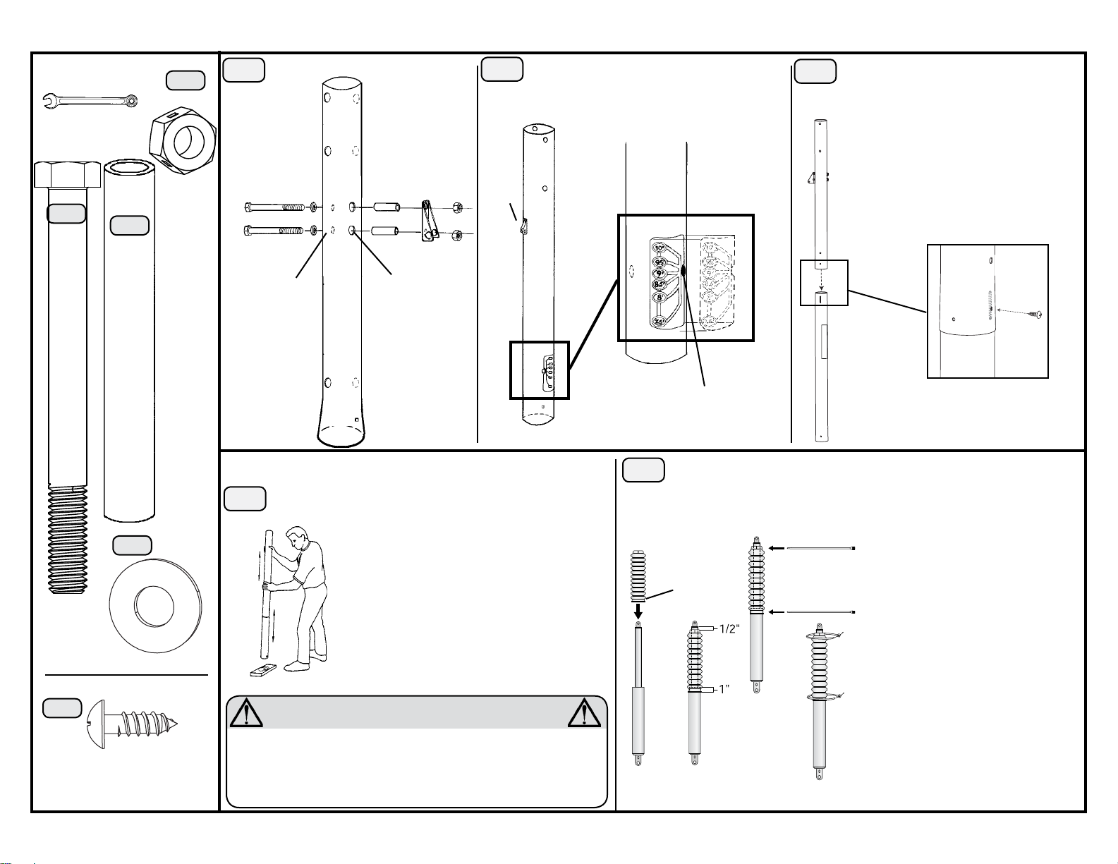
Required For This Page:
9/16” Wrenches
Screwriver
1039829
HC
(2)
6.1 Completely tighten the Nuts.
6
TP
7.1 Apply the Height Sticker (AL) so it wraps
7
around the opposite side of the pole as the
Spring Bracket (AM).
8.1 Align the hole in the Top Pole with the
8
slot in the Middle Pole and slide the Top
Pole over the Middle Pole.
Do not jam the poles together until instructed.
8.2 Insert a 1/4” x 3/4” Screw (PA)
through the small hole in the Top Pole
and into the Middle Pole.
MJ
(2)
MT
(2)
BC
(2)
MJ
Small holes
AM
Large
holes
HCMTBC
AM
This step cannot be reversed.
9.1 Strike each end of the Pole firmly 5 to 6 times on a piece of
9
scrap wood or cardboard.
Warning: If the Top and Middle Poles do not completely cover
TP
the slots on the Middle and Bottom Poles after seating, DO NOT
COMPLETE ASSEMBLY. Call our Customer Service Department.
AL
Note: The small notch in the Sticker
fits around the hole in the pole.
10.1 The bottom of the Bellows (AS) overlaps the Gas Spring (AN) by 1”. The
10
top is 1/2” from the top of the Spring.
AS
Larger End
TP
MP
Zip Tie (AK)
Zip Tie (AK)
Note: There are two screw holes at the
bottom of the pole. The correct hole will
be slightly larger and slightly higher up on
the pole.
PA
Note: The Screw will spin freely once
installed.
PA
(1)
1005748
MP
Warning: Do not hit your feet with the pole sections, as
serious injury could occur.
WARNING
The poles must be seated together!! Even if the poles cover the slots
before seating, you must strike them on the wood five to six times!! Failure
to seat the poles correctly could allow the poles to separate during use,
which could lead to serious personal injuries or property damage as
listed on Page One.
AS
AN
10.2 Use pliers to tighten the Zip Ties (AK) securely. Cut off the ends of the Zip Ties.
AN
6
Page 7
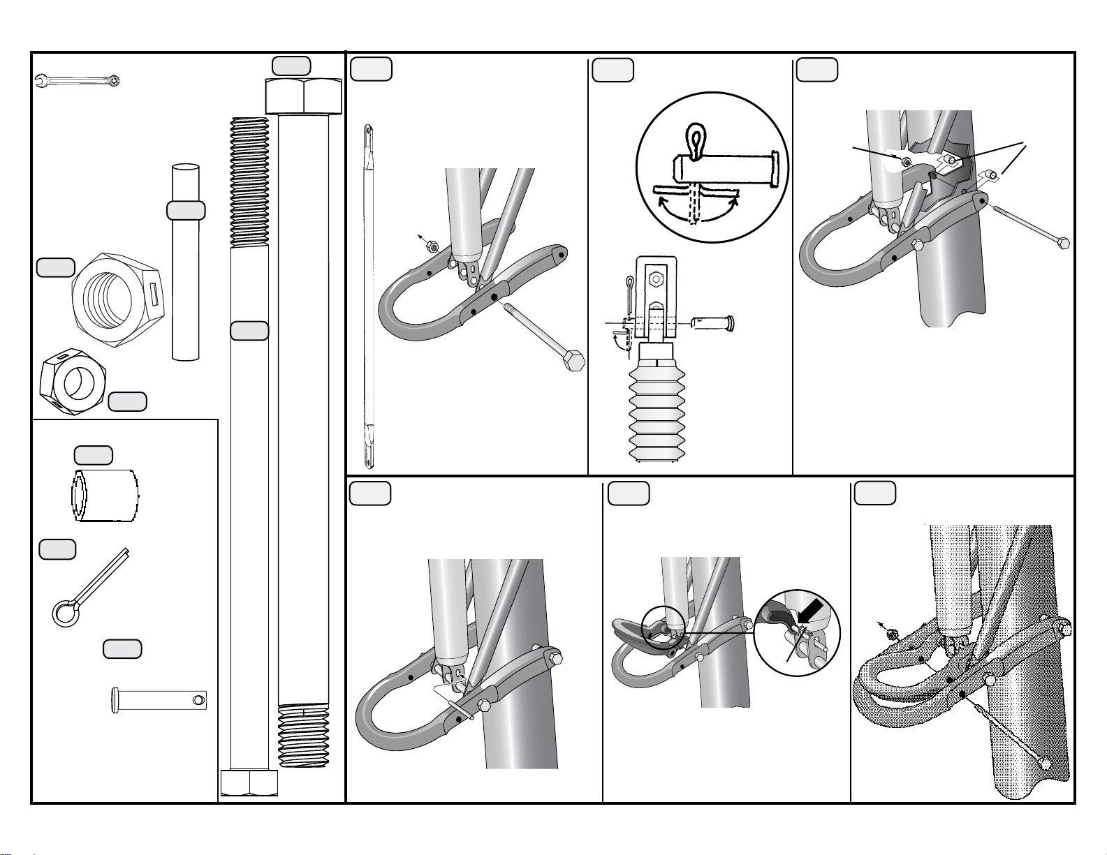
Required For This Page:
1/2” Wrenches
9/16” Wrenches
3/4” Wrenches
Scissors/
Wire Cutters/
Pliers
Hammer/
Mallet
MH
(1)
1017923
HB
(1)
HD
(1)
11.2 Tighten the Nut until it is flush with the Bolt.
11.1 Line up the Rear Lifter Arms
11
(AR) with the Gas Spring (AN).
AR
AN
AR
MH
AR
12
above.
MD
12.1 Use pliers to bend the
Cotter Pin (MD) as shown
MD
AM
ME
13
AC
13.1 Tighten the Nut until it is flush with
the Bolt.
HC
7
MO
HA
1039829
MO
MD
(1)*
(2)
HC
(2)
ME
(1)*
*(Not actual
size)
HA
(2)
AC
14.1 Slide the Release Pin (HB)
14
through the oval holes of the clevis at
the end of the Gas Spring (AN).
AN
HB
HD
15
(AD).
AD
ME
AN
15.1 The Release Pin (HB) should
fit into the channels in the Trigger
AC
HB
16.1 Tighten the Nut (HC) until it is
16
flush with the Bolt.
HC
AD
AC
HA
Page 8
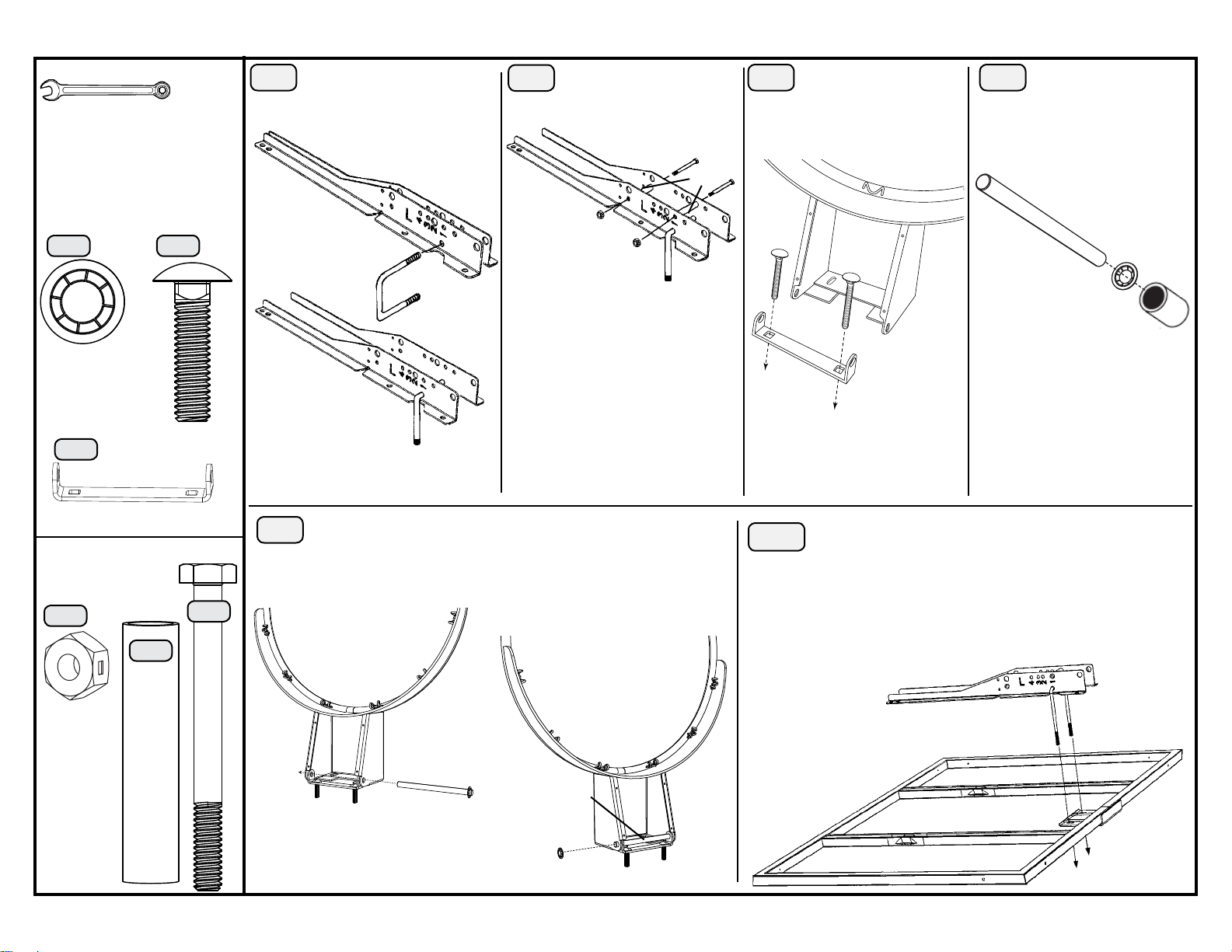
Required For This Page:
9/16” Wrenches
Pliers
1/2” Socket Wrench
1003678
(2)
17.1 Hold the Backboard
17
Brackets (AP & AQ) together
and slide the U-Bolt (RE) through the
holes as shown.
AP
AQ
(2)
RCRB
RE
18.1 Ensure the U-Bolt (RE)
18
is in the notches.
AP
AQ
MB
MB
MI
RE
through each hole in the Rim Pivot
Bracket (RI).
ML
MI
RC
19.1 Insert a 5/16” x 1
19
1/4” Carriage Bolt (RC)
RC
AO
20.1 Use the 1/2” socket
20
head from the socket head
wrench to press one Push Nut (RB)
onto one end of the Axle (RH).
RH
RB
(1)
RI
(Not actual size)
1039829
(2)
MB
ML
(2)
MI
(2)
21
18.2 Completely tighten the Nuts
(MA).
RE
21.1 Slide the end of the Axle (RH) through the Rim (AO) and the
Rim Pivot Bracket (RI). Press the Push Nut (RB) onto the end
of the Axle. Use the 1/2” socket head to secure the Push Nut if
needed.
AO
RI
RH
RH
RI
22
Note: The U-Bolt (RE) goes
through the top holes in the
Backboard.
22.1 Lay the Backboard (AU) on a table or bench.
Note: The Push Nut should rest about
1/4” from the end of the Axle. If the
Push Nut slips on too far, continue
sliding it to the other end of the Axle to
remove it and try again.
RE
RB
AU
8
Page 9
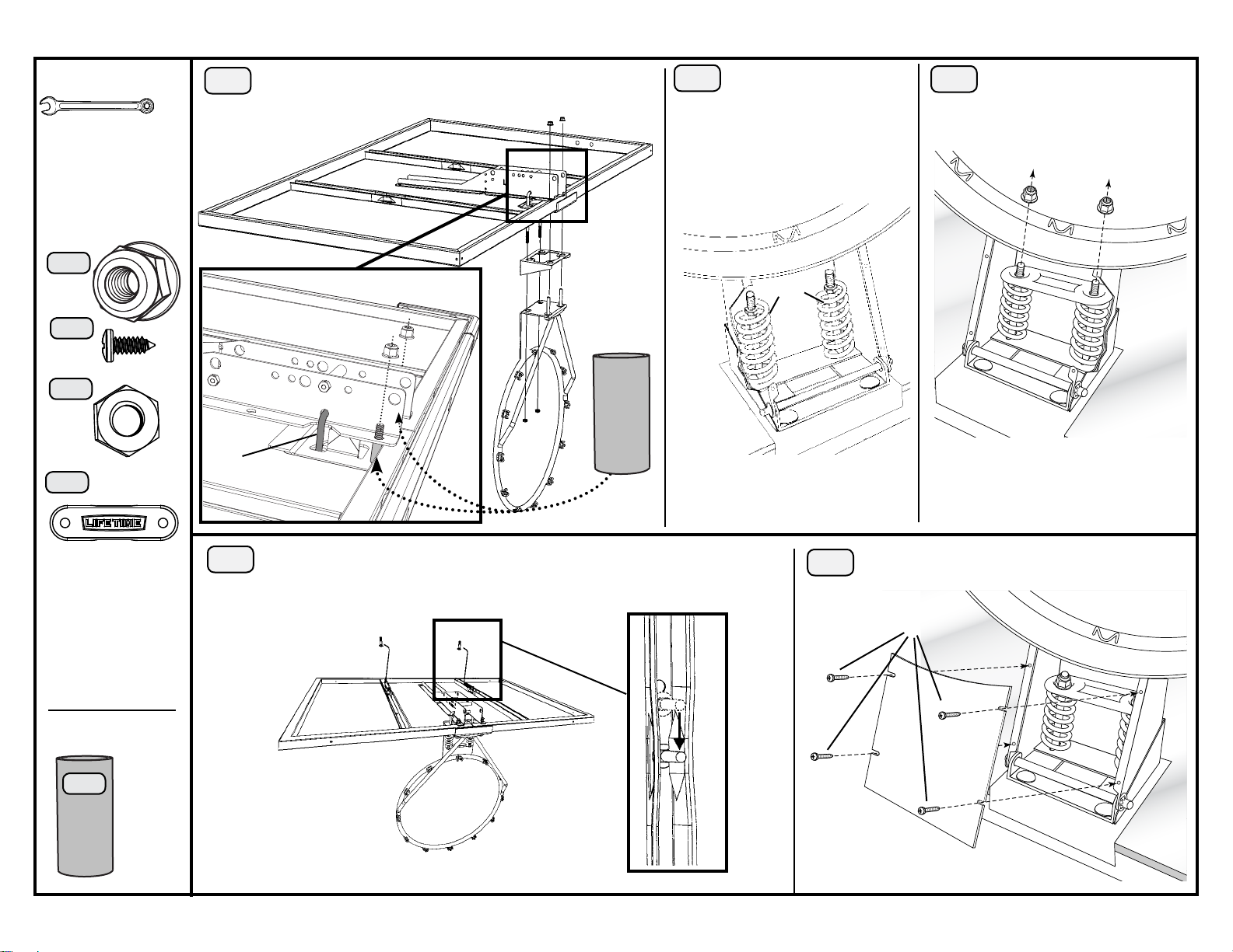
Required For This Page:
1/2” Wrench
3/4” Wrenches
Electric Drill/
Screwdriver
1003678
RF
(4)
RA
(4)
23.1: Slide a Spacer (MC) over each Tap Bolt (RC) between
23
the Backboard and the Backboard Brackets.
AF
RF
Only hand
tighten the
Nylock Flange
Nuts (RG).
24
24.1 Place the Compression
Springs (RG) over the ends of
the U-Bolt (RE).
RG
25
9
25.1 Place the Spring Retainer Plate
(RJ) and secure with Nylock Flange
Nuts (RF).
RF
RF
RJ
RD
(2)
(1)
RJ
(Not actual
size)
1039829
MC
(2)
RE
26
MC
RD
26.1 Slide a Carriage Bolt (MX) into the crimped slot in each
Backboard channel.
MX
MX
MX
Note: Do not overtighten the Nuts
(RF).
27.1 Attach the Rim Cover Plate (AX) to the Rim using #7
27
x 3/8” Screws (RA).
RA
AX
Page 10
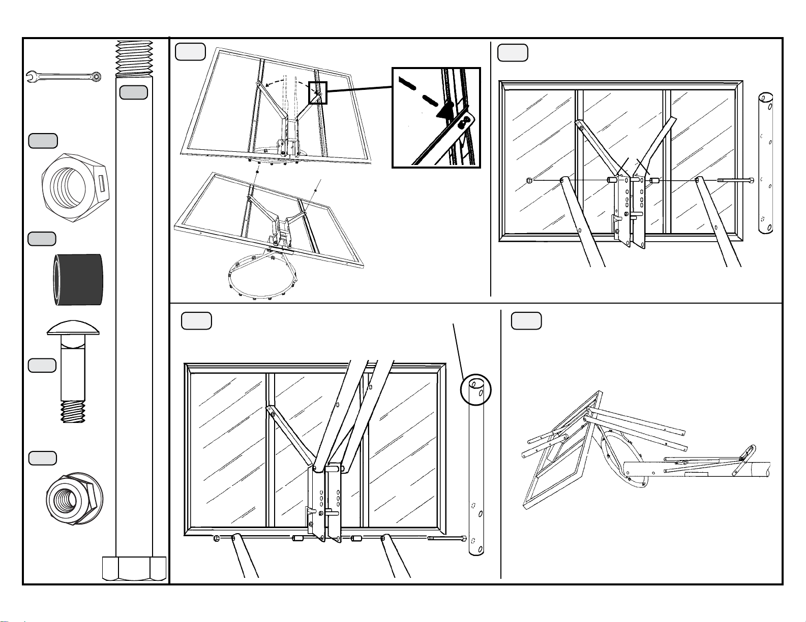
Required For This Page:
1/2” Wrench
3/4” Wrenches
MA
(2)
28
28.1 Bend the Backboard Brackets (AP & AQ) out
and over the Carriage Bolt (MX).
29.1 Tighten the Nut until it is flush with the Bolt.
29
10
AA
1039829
MH
(2)
MZ
(4)
MX
(2)
AQ
MY
30.1 Attach this end of the Long Extension Arms (AE) to the Backboard
30
Brackets (AP & AQ).
30.2 Tighten the Nut until it is flush with the Bolt.
AP
MY
Note: The lower holes
should go over the Carriage
Bolts.
28.2 Secure Brackets with 5/16 “
Nylock Flange Nuts (MY).
28.3 Completely tighten all Rim
hardware.
Note: Do not overtighten the Nuts (MY).
MZ
MH
AA
31.1 Rest the Backboard (AU) and Rim (AO) on cardboard
31
to prevent scratching.
MA
AA
MY
(2)
MH
AE
MZ
AE
MZ MA
AE
Page 11
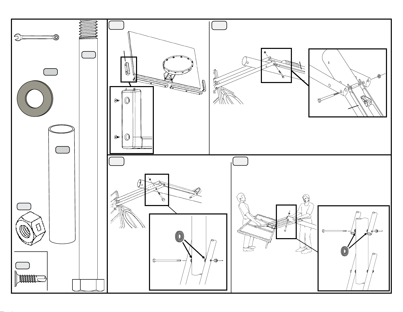
Required For This Page:
3/4” Wrenches
1/2” Socket Wrench
Hammer/Mallet
Electric Drill
1039829
MN
(4)
MA
(3)
32.1 Remove the plastic film from the
32
Backboard.
FL
FR
33.1 Lift the pole up until the Long Extension Arms (AE) line up with the holes in the
33
Rear Lifter Arms (AR).
AP
AE
AE
MR
AE
MH
MH
(3)
MR
(1)
FA
FA
34.1 There must be a 1/2” x 1/8” Spacer (MN) between
34
each Long Extension Arm (AE) and the pole.
AE
FB
FB
32.2 Use an electric drill to
insert the Screws (FA).
MN
MA
33.2 Only finger tighten the Nut.
Note: The Rear Lifter Arms (AR) must be on the inside of the Extension Arms (AE).
35.1 Place a 1/2” x 1/8” Spacer (MN) between each Short Extension
35
Arm (AA) and the pole.
MA
AR
AA
AR
AA
MH
HH00700
(10)
FA
34.2 Only finger
tighten the Nut.
MA
AE AE
MH
MN
35.2 Completely tighten the Nuts from steps 33
through 35.
11
Page 12
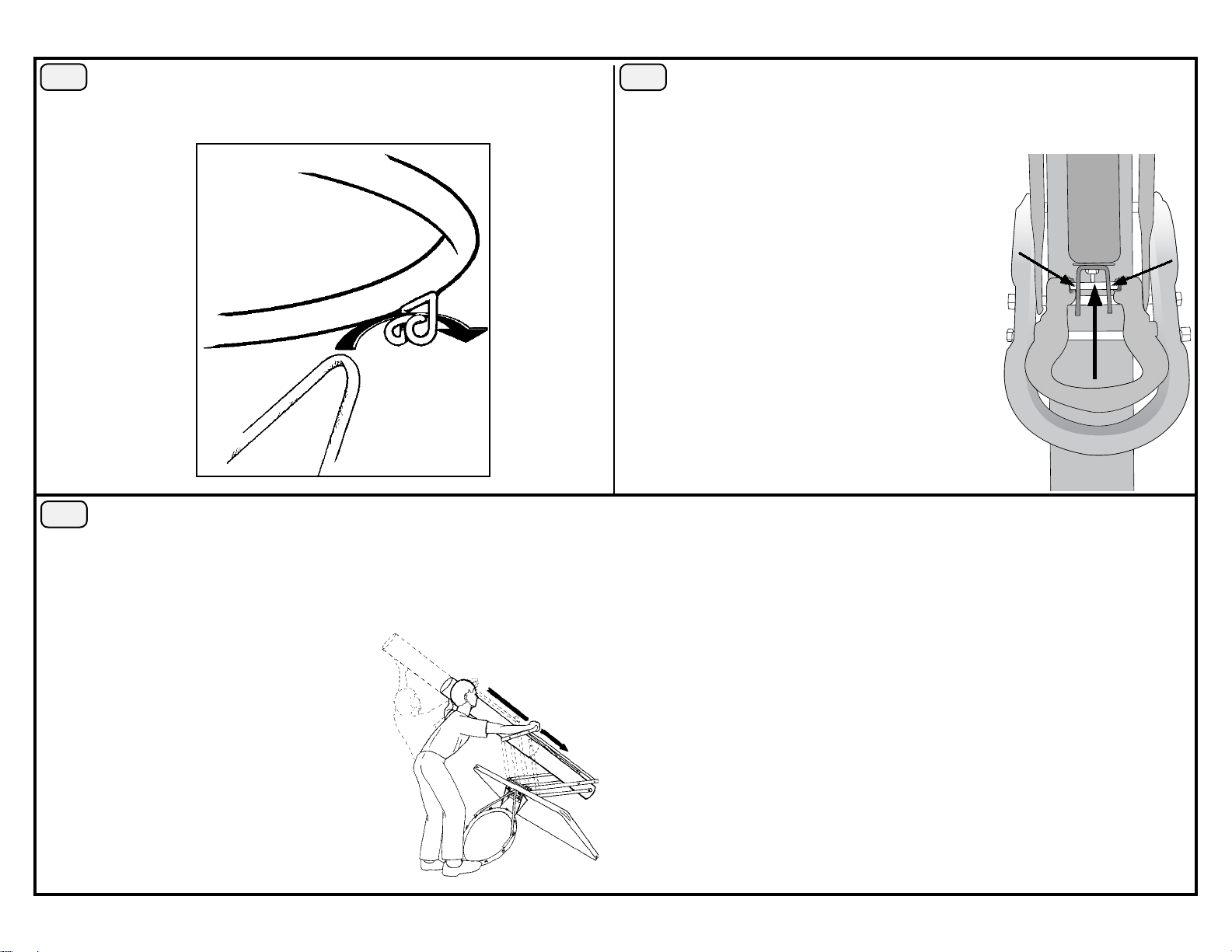
12
36.1 Attach the Net (AB).
36
Note: Please call our Customer Service Department at the number on Page One to obtain replacement Nets. Our
Nets are shorter than average to reduce the risk of entanglement.
AO
AB
38.1 Slowly lift the pole and rotate the Backboard assembly upside down
38
again.
37.1 Apply the Grease (MQ) to these areas.
37
CAUTION: DO NOT APPLY EXCESSIVE WEIGHT TO THE HANDLE. Do not hang anything from the Handle, as this will damage the
system and void the product warranty.
38.2 Grasp the Handle and Trigger as shown. Squeeze the Trigger and push
down on the pole to compress the Gas Spring.
38.3 Release the Handle before letting go of the pole.
CAUTION: When compressing the Gas Spring, use extreme
caution to prevent the pole from extending.
Page 13
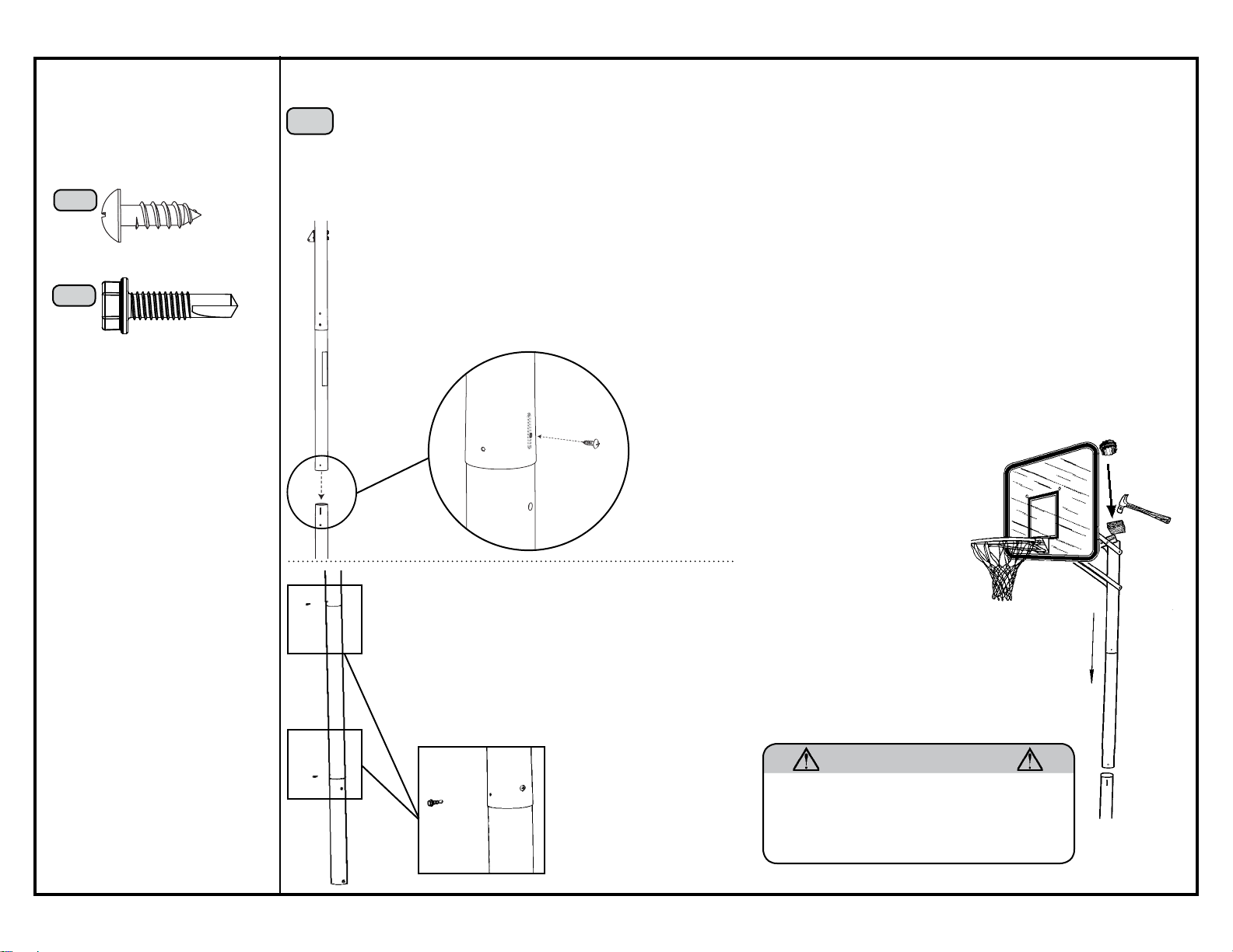
Required For This Page:
Screwdriver
Hammer/Mallet
Electric Drill
1005748
PA
(1)
**AT LEAST 2 ADULTS REQUIRED FOR THIS STEP**
39.1 Ensure the Backboard faces the playing surface and align the small hole in the Middle Pole (MP) with the correct slot in the Bottom Pole (BP).
39
Slide the Middle Pole over the Bottom Pole.
39.2 Insert the remaining 1/4” x 3/4” Screw (PA) through the small hole in the Middle Pole and into the Bottom Pole. The Screw will spin
freely once installed.
Note: There are two screw holes at the bottom of the pole. The correct hole will be slightly larger and slightly higher up on the pole.
39.3 Place the Wood Block (AJ) on top of the pole and strike with a hammer six or
TP
seven times.
13
PB
(2)
PB
Warning: If the Middle Pole does not completely cover the slot on the Bottom Pole after seating, DO NOT COMPLETE ASSEMBLY. Call our Customer
Service Department.
MP
PA
BP
39.4 Place a Self-tapping Screw (PB) directly into the
chuck of the Electric Drill and insert the screw into the
back of the poles at the locations shown.
Note: To ensure that the concrete can fully set, do
not play aggressively on your basketball system
39.5 After setting the poles in step 39.3, Insert
the Pole Cap (AW) into the pole.
for a week.
AW
AJ
TP
MP
PB
PB
WARNING
Use extreme caution when standing on ladders to
perform assembly steps. Follow all warnings and
cautions on the ladder. Failure to follow all of these
instructions and warnings could lead to serious
personal injury or property damage.
BP
Page 14
Operation of the height adjustment system
The adjustable system may be adjusted from 7 1/2 feet to 10 feet.
Hold the Handle tightly and squeeze the Trigger to engage the Gas Spring. Raise the Handle to lower the Backboard, or lower
the Handle to raise the Backboard.
WHILE TRANSPORTING THE PORTABLE SYSTEM, USE CAUTION TO PREVENT THE MECHANISM FROM ADJUSTING.
Moving the system
WARNING: The system must only be moved by people capable of handling its weight. Children should not be allowed to move the system.
a. Adjust the system to its lowest position.
b. Stand in front of the system and pull on the pole until the unit is balanced on its Wheels.
c. Move the system to the desired location and carefully set the Base down.
POLE CARE AND SYSTEM MAINTENANCE
The life of your basketball system depends on many variables. The climate, exposure to corrosives
such as salt, pesticides, or herbicides, and excessive use or misuse can all contribute to
pole failure, which may cause property damage or personal injury.
Check your basketball system frequently for loose hardware, excessive wear, and signs of
corrosion. For safety reasons, and to prolong the life of your basketball system, you must
take the following preventive measures.
a. Check all Nuts and Bolts. If any are loose, tighten them.
b. Check all parts for excessive wear and tear. If necessary, replace any parts that have been
worn or damaged through usage. Check the Pole Cap for cracks or tears that could let water
into the pole. Contact our Customer Service Department for replacement parts.
c. Inspect the Warning Sticker on the pole. If it is ripped, faded, or illegible, call our Customer
Service Department to request a replacement Sticker.
d. Check all pole sections for visible rust or chipped or cracked paint. If either are present, do
the following:
1. Use an emery cloth to completely remove any rust or chipped paint.
2. Clean the area with a damp cloth and allow it to dry.
3. Apply two coats of a rust preventative, high gloss enamel paint to the area. Allow the
paint to dry between coats.
IF RUST HAS PENETRATED THROUGH THE POLE ANYWHERE, REPLACE IT IMMEDIATELY!
ACCESSORIES AVAILABLE FOR MORE BASKETBALL FUN!
PRODUCT DESCRIPTION MODEL # Intermediate
Size Basketball 594201 Universal Ground
Sleeve 0023
Contact Customer Service at the number on
Page Two for prices and freight cost.
Universal Ground Sleeve
#0023
The Universal Ground Sleeve enables the pole to be cemented
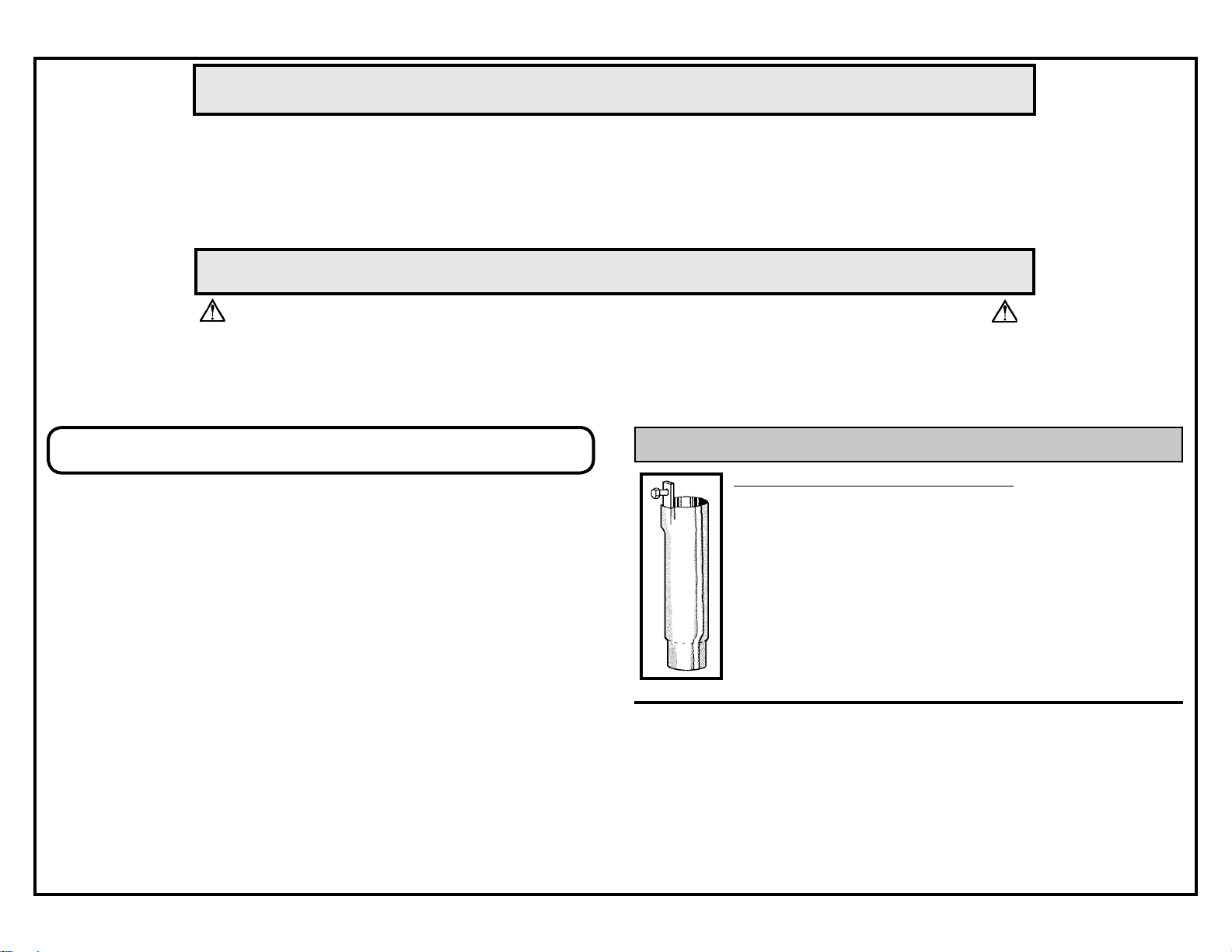
in, yet still removable. The sleeve sits flush with the ground
after installation. Fits 3.5” diameter poles.
Only clean the Backboard with the approved cleaning materials
listed below:
Windex
1
Joy2
Mr. Clean
2
The use of other chemicals will void the warranty.
1
Registered Trademark of the Drackett Products Company.
2
Registered Trademarks of Procter & Gamble.
3
Registered Trademark of Texize, Division of Norton Norwich Products Inc.
4
Registered Trademark of the Clorox Company.
Fantastik
Formula 409
3
4
14
Page 15
or lifter arms as this will damage the system
15
www.lifetime.com
etc. could cause corrosion and/or deterioration.
and repaint with exterior enamel. If rust has penetrated any
corrosion (rust, pitting, chipping). Completely remove rust
steel part, replace that part immediately.
excessive wear, instability, and signs of corrosion and repair
Keep organic material away from pole base. Grass, litter,
Once a month check pole and all metal parts for signs of
Check system before each use for loose hardware,
before use.
backboard and rim. Do not hang anything from the handle,
mechanism is designed to lift only the weight of the
Never play on damaged equipment.
Do not use the system to lift or hoist anything. The
WARNING
DAMAGE.
these rules for safe operation of the system.
FAILURE TO FOLLOW THESE WARNINGS MAY
Owners must ensure that all players know and follow
RESULT IN SERIOUS INJURY AND/OR PROPERTY
injuring others. Release the rim as soon as safely possible.
keep player’s face away from the backboard, rim, and net.
Serious injury could occur if teeth/face come in contact with
Only hang from the rim briefly to regain balance or avoid
During play, especially when performing dunk type activities,
the backboard, rim, or net. Player should wear a mouth
AVERTISSEMENT
and void the warranty.
rim backboard,
ADVERTENCIA
guard during play.
fingers away from moving parts.
Do not slide, climb, or play on pole.
When adjusting height or moving system, keep hands and
play. Objects may entangle in net.
Do not allow children to move or adjust system.
Do not wear jewelry (rings, watches, necklaces, etc.) during
d’utiliser l’équipement en toute sécurité.
Le propriétaire doit s’assurer que tous les joueurs
VOUS RISQUEZ DE CAUSER DES BLESSURES
FAUTE DE NE PAS SUIVRE CES AVERTISSEMENTS,
connaissent et appliquent les règles suivantes afin
•Ne vous suspendez pas à l’anneau plus que nécessaire
pour retrouver votre équilibre ou éviter de blesser les autres
joueurs. Relâchez l’anneau aussitôt que possible.
• Lors d’un match, particulièrement dans le cas des smashs,
le visage du joueur ne doit pas faire face au panneau, à
l’anneau, ni au filet. Le joueur risque de graves blessures si
ses dents ou son visage entrent en contact avec le panneau,
l’anneau, ou le filet. Les joueurs doivent toujours porter un
protège-dents lorsqu’ils jouent.
• Ne glissez pas, ne grimpez pas, et ne jouez pas sur la base
ou le poteau.
GRAVES ET/OU DES DOMMAGES À L’ÉQUIPEMENT.
• Lorsque vous ajustez la hauteur ou l’équipement, gardez
DAÑOS A LA PROPIEDAD.
para que el sistema se use en forma segura.
SI NO SE OBEDECEN ESTAS ADVERTENCIAS
El propietario del sistema debe asegurarse de que
PUEDEN PRODUCIRSE GRAVES LESIONES Y/O
todos los jugadores conozcan y respeten estas reglas
• Cuélguese del aro sólo en forma breve, para recuperar el
equilibrio o evitar lesionar a otros jugadores. Suéltese del
aro lo más pronto que pueda hacerlo con seguridad.
• Durante el juego, especialmente al embocar violentamente
de alto, la cara de los jugadores debe mantenerse alejada
del tablero, el aro y la red. Pueden producirse lesiones
graves si los dientes o la cara entran en contacto con
el tablero, el aro o la red. Los jugadores deben usar un
protector bucal durante el juego.
• No se deslice, no trepe ni juegue sobre el poste.
• Mantenga las manos y los dedos alejados de las piezas
movibles cuando regule la altura del sistema.
les déchets, etc. peuvent la corroder et la
détériorer.
• Une fois par mois, vérifiez que le poteau et toutes les pièces
en métal ne montrent pas de signes de corrosion (rouille,
piqûres, écaillage). Enlevez toute la rouille et repeignez
a pénétré une des pièces en acier, vous devrez remplacer
complètement avec une peinture pour extérieur. Si la rouille
immédiatement la pièce en question.
• A chaque fois que vous allez utiliser l’équipement, vérifiez
usées, la stabilité de l’équipement et tout signe de corrosion
ou réparation nécessaire avant utilisation.
lorsque vous jouez. Ces objets pourraient s’accrocher au
filet.
• Ne portez pas de bijoux (bagues, montres, colliers, etc.)
durante el juego. Estos objetos pueden engancharse en la
red.
• Gardez la base du poteau libre de toute matière organique.
L’herbe,
pieza
• No permita que la base del poste entre en contacto con
pueden causar corrosión y/o deterioros.
• Controle el poste y todas las piezas metálicas una vez al
materiales orgánicos. El pasto, los desechos animales, etc.,
mes en busca de signos visibles de corrosión (oxidación,
picaduras, escamado). Elimine todo rastro de óxido y
vuelva a pintar con esmalte para exteriores. Si el óxido ha
penetrado cualquier pieza de acero, reemplace esa
vos mains et doigts loin des pièces mobiles.
• N’autorisez pas les enfants à ajuster l’équipement.
• No deje que los niños regulen el sistema.
• No use joyas (anillos, relojes, collares o gargantillas, etc.)
d’abord l’équilibre, la possibilité de pièces desserrées ou
de inmediato.
• Inspeccione el sistema antes de cada uso para verificar
que los elementos de fijación no estén flojos, que no haya
desgaste excesivo, inestabilidad ni signos de corrosión.
Si encuentra irregularidades, repárelas antes de usar el
sistema.
• Ne jouez jamais avec un équipement endommagé.
• N’utilisez pas l’équipement pour lever ou soulever quoique
ce soit. Son mécanisme a été conçu uniquement pour
soutenir le poids du panneau et de l’anneau. N’accrochez
rien au manche, à l’anneau, au panneau ni aux leviers sous
peine d’endommager l’équipement et d’annuler la garantie.
10/12/2004
#FS16500
• Nunca juegue con un equipo dañado.
• No use el sistema para levantar ningún objeto. El
mecanismo está diseñado para elevar solamente el peso
del tablero con el aro. No cuelgue nada de la agarradera, el
aro, el tablero ni los brazos de elevación, ya que esto puede
dañar el sistema y anular la garantía.
Page 16

LIFETIME BASKETBALL EQUIPMENT
7
5-YEAR LIMITED FACTORY WARRANTY
THE MANUFACTURER RESERVES THE RIGHT TO MAKE SUBSTITUTIONS TO WARRANTY CLAIMS IF PARTS ARE UNAVAILABLE OR OBSOLETE.
1. Lifetime basketball systems are warranted to the original purchaser to be free from defects in material or workmanship for a period of
five years from the date of original retail purchase. The word “defects” is defined as imperfections that impair the use of the product.
Defects resulting from misuse, abuse or negligence will void this warranty. This warranty does not cover defects due to improper
installation, alteration or accident. This warranty does not cover damage caused by vandalism, rusting, “acts of nature” or any other
event beyond the control of the manufacturer.
2. This warranty is nontransferable and is expressly limited to the repair or replacement of defective basketball equipment. If the equipment
is defective within the terms of this warranty, Lifetime Products, Inc. will repair or replace defective parts at no cost to the purchaser. Shipping
charges to and from the factory are not covered and are the responsibility of the purchaser. Labor charges and related expenses for removal,
installation or replacement of the basketball system or its components are not covered under this warranty.
3. This warranty does not cover scratching or scuffing of the product that may result from normal usage. In addition, defects resulting from
intentional damage, negligence, unreasonable use or hanging from the net or rim will void this warranty.
4. Liability for incidental or consequential damages is excluded to the extent permitted by law. While every attempt is made to embody the highest
degree of safety in all equipment, freedom from injury cannot be guaranteed. The user assumes all risk of injury resulting from the use of this
product. All merchandise is sold on this condition, and no representative of the company may waive or change this policy.
5. This product is not intended for institutional or commercial use; Lifetime Products, Inc. does not assume any liability for such use. Institutional
or commercial use will void the warranty.
6. This warranty is expressly in lieu of all other warranties, expressed or implied, including warranties of merchantability or fitness for use. Neither
Lifetime Products, Inc., nor any representative assumes any other liability in connection with this product.
ALL WARRANTY CLAIMS MUST BE ACCOMPANIED BY A SALES RECEIPT.
REPORT PRODUCT DEFECTS IN WRITING TO:
Lifetime Products, Inc., PO Box 160010 Clearfield, UT 84016-0010
or call (800) 225-3865 M-F 8 a.m. to 5 p.m. MST.
Please include your dated sales receipt and photographs of damaged parts.
To Register Your Product, Visit Our Website at www.lifetime.com
16
 Loading...