

Lifetime 1270 Owner's Manual
1
Copy
2
INSTRUCTION #1025093
The product you just purchased could be FREE!
Register your product at www.lifetime.com and receive three important
benets:
1. You automatically will be entered to win $200 in our monthly drawing!
2. In the unlikely event of a product recall or safety modication, we can
notify you immediately and directly.
3. You may choose to receive Preferred Customer Announcements and
promotions regarding new Lifetime products.
www.lifetime.com
**U.S. and Canada customers ONLY**
IF ASSISTANCE IS NEEDED,
DO NOT CONTACT THE STORE!!!
CALL OUR CUSTOMER SERVICE DEPARTMENT at 1 (800) 225-3865
HOURS: 7:00 a.m. to 5:00 p.m. Monday through Friday (Mountain Standard Time)
Call, or visit our Website for Saturday hours.
Save this instruction in the event that the manufacturer has to be contacted for
replacement parts.
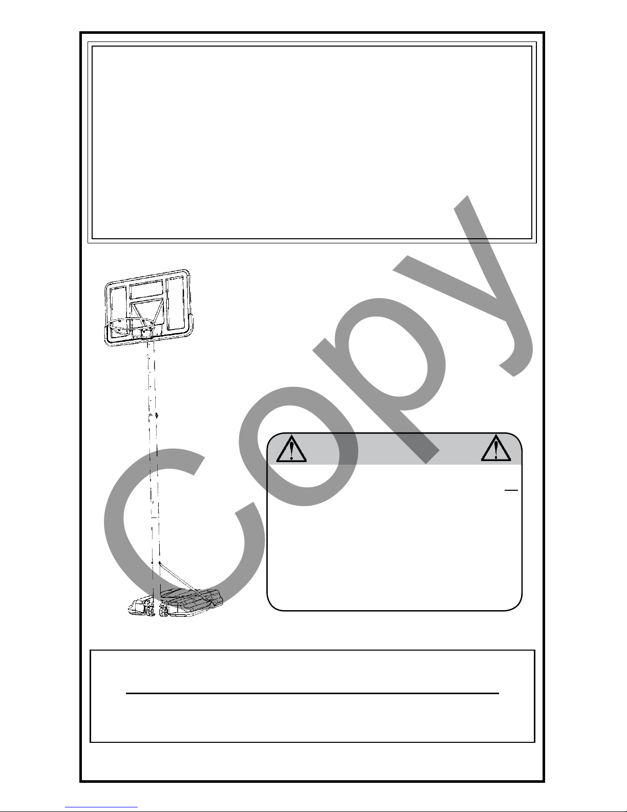
MODEL #1270
WARNING
To ensure your safety, do not attempt to assemble
this system without reading and following all
instructions carefully. Identify and inventory the
parts using the Parts List. Failure to comply with
any of the warnings in these instructions may
result in serious personal injuries such as cuts,
broken bones, nerve damage, paralysis, brain
injury, or death. Failure to comply may also result
in property damage. Please heed all warnings
and cautions.
PROCOURT®
BASKETBALL SYSTEM
2/6/2007
**For customers outside the U.S. or Canada, please contact the store for assistance.**
Copy
3
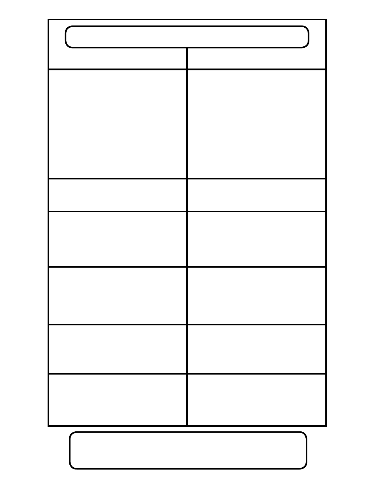
Problem / Possible Cause
ASSEMBLY TROUBLESHOOTING
1. Identify your pole sections:
TOP: Crimped end with six holes down the
middle.
MIDDLE: Warning Sticker.
BOTTOM: A slot at the top of the pole, two
holes near the middle of the pole and four
holes at the bottom.
2. Slide the Top Pole inside the bottom of
the Middle Pole, crimped end rst, until
it extends out of the top of the Middle
Pole. There should be no hardware or parts
attached to either pole at this point.
2. My Top Pole will not slide through my
Middle Pole:
The pole sections are not completely round.
Align the holes in the side of the Top Pole with
the holes in the Middle Pole section before
sliding it through.
1. My Top and Middle Poles will not
assemble:
It is easy to confuse the pole sections. Refer
to the next column for hints on how to tell
them apart.
3. How do I fasten my poles together?
The Top and Middle Pole sections are
fastened together with a Carriage Bolt
through both poles. The Bottom and Middle
Pole sections are held together with a friction
weld and also with a pole joint Screw.
Follow the instructions for pole assembly
carefully. When the poles are seated together,
a friction weld is created between the Bottom
and Middle Pole sections. A pole joint Screw
will also be attached.
4. My Pole Braces will not attach:
The Pole Braces are designed to t snugly
to the Base and the Bottom Pole section for
stability.
The Pole Braces should be attached to the
Base rst, but the hardware should only be
nger tight at this point. Use gentle pressure
on the Pole Braces to align them with the holes
in the Bottom Pole. Then completely tighten
all Base hardware before proceeding.
5. H ow d o I b e n d my B a c kboard
Brackets?
Although the Backboard Brackets are made
of steel, they are designed to bend with only
a small amount of force.
The Backboard Brackets should be fastened
nger tight to the Rim holes in the Backboard.
Grasp the tops of the Backboard Brackets and
bend them away from each other with steady
force.
Solution
Who Do I Call If I Have
Questions Or Problems?
1-800-225-3865
HOURS:
7:00 AM – 5:00 PM MST
MONDAY – FRIDAY
**A MINIMUM OF TWO ADULTS ARE
REQUIRED FOR ASSEMBLY**
4
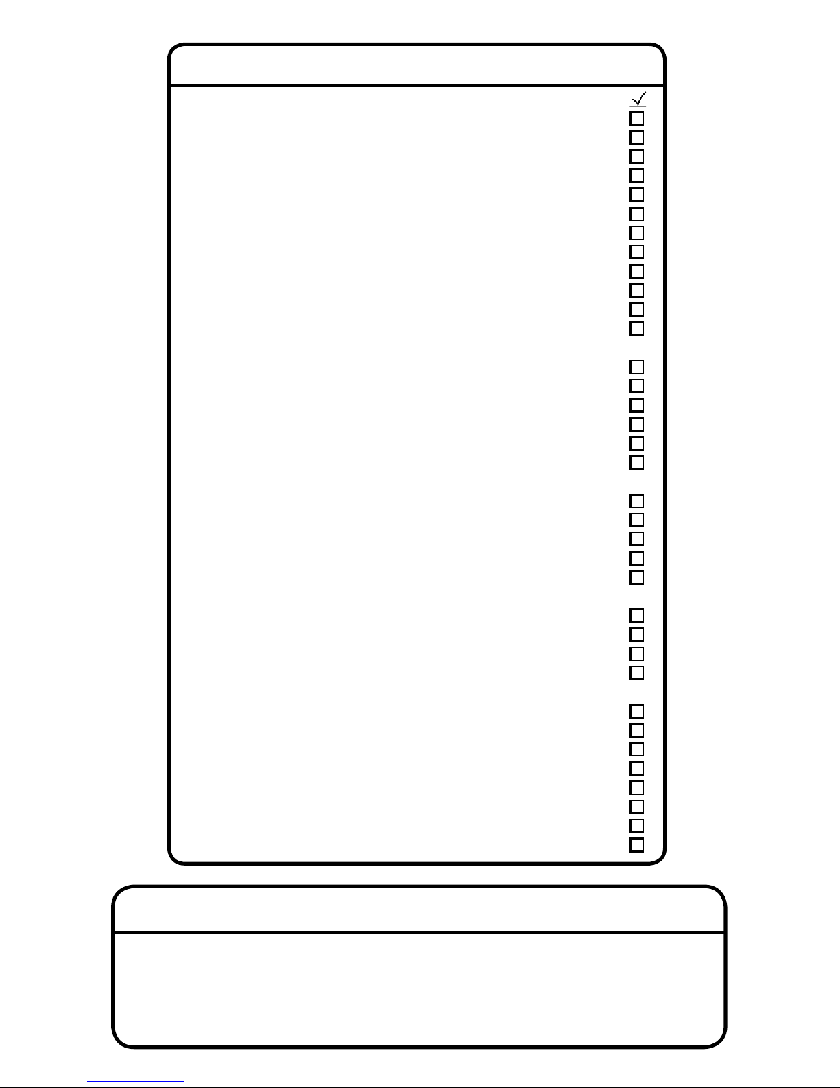
PARTS LIST
ID Part # Description Qty
TP 1018558 Top Pole 1
MP 1018559 Middle Pole 1
BP 1018560 Bottom Pole 1
LB 1018713 Left Backboard Bracket 1
RB 1018711 Right Backboard Bracket 1
BB 1025145 Backboard 1
AA 510022 Wheel 2
AB B110001 1/2” x 15 3/4” Axle 1
AC 1002834 Base 1
FS16400 Warning Sticker (Applied) 1
AD 1018886 Rim 1
AE 1018850 Pole Brace 2
Main Hardware (1001200)
MA BS02000 1/4” x 3/4” Self-Drilling Screw 1
MB 300095 5/16” Cap Nut 1
MC 302014 5/16” Flat Washer 1
MD 302012 5/16” Zinc-Plated Nut 1
ME CH06899 Pole Locking Knob 1
MF 1000805 5/16” x 3 1/4” Carriage Bolt 2
Rim Hardware (HP18600)
RA 300027 5/16” x 1 3/4” Hex Bolt 2
RE BB01400 2” U-Bolt 1
RC 302090 5/16” Nylock Flange Nut 4
MC 302014 5/16” Flat Washer 4
RD DD00200 Net 1
Backboard Hardware (1002576)
PA BS00800 5/16” x 1” Screw (for plastic) 2
PB 300075 5/16” Flange Lock Nut 2
PC 302062 5/16” x 3 1/4” Hex Bolt 2
PD AM01500 Rim Support Channel 1
Base Hardware (1007262)
BA CF00199 1 1/4” Base Plug 2
BB 300097 5/16” Nylock Nut 2
BC 300030 5/16” x 1” Hex Bolt 2
MC 302014 5/16” Flat Washer 4
BE 500032 1/2” x 1/8” Spacer 2
BF BD00200 1/2” x 7” Axle 1
HA 1003221 1/4” T-Nut 1
HB 1003222 1/4” Hex Shoulder Screw 1
Tools and Materials Required for Assembly
(Not Included)
1. Adjustable Wrench
2. 319 lbs. of Sand/ Water Supply
3. 1/2” Wrenches (2)
4. Funnel
5. Phillips Screwdriver
6. Scrap Wood/Cardboard
7. 3/8” Socket Wrench
8. 7/16” Wrench
9. Pliers
5
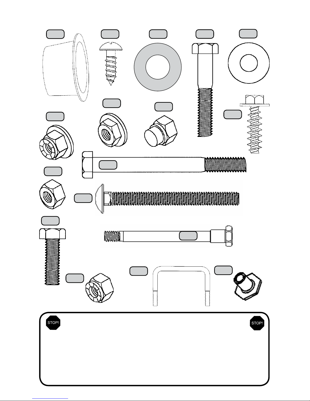
BA
MC
RC
RA
MF
BB
BC
MD
MB
PC
HARDWARE IS ACTUAL SIZE
PA
PB
MA BE
Before Beginning Assembly
A. Keep the hardware bags and their contents separate. If any
parts are missing, call our Customer Service Department.
B. TesttallBoltsbyinsertingthemintotheirrespectiveholes.
If necessary, carefully scrape away any excess powder coating
buildup from inside the holes. Do not scrape away all of the
powder coating. Bare metal may rust.
RE
(Not actual size)
HB
HA
 Loading...