

Life technologies EVOS FL, EVOS FL Color User Manual

USER GUIDE
EVOS® FL
EVOS® FL Color
Imaging Systems for Fluorescence
and TransmittedLight Applications
Catalog Numbers AMF4300, AMEFC4300
Publication Number MAN0007988
Revision 1.0
For Research Use Only. Not for use in diagnostic procedures.

Information in this document is subject to change without notice.
DISCLAIMER
LIFE TECHNOLOGIES CORPORATION AND/OR ITS AFFILIATE(S) DISCLAIM ALL WARRANTIES WITH
RESPECT TO THIS DOCUMENT, EXPRESSED OR IMPLIED, INCLUDING BUT NOT LIMITED TO THOSE OF
MERCHANTABILITY, FITNESS FOR A PARTICULAR PURPOSE, OR NON-INFRINGEMENT. TO THE EXTENT
ALLOWED BY LAW, IN NO EVENT SHALL LIFE TECHNOLOGIES AND/OR ITS AFFILIATE(S) BE LIABLE,
WHETHER IN CONTRACT, TORT, WARRANTY, OR UNDER ANY STATUTE OR ON ANY OTHER BASIS FOR
SPECIAL, INCIDENTAL, INDIRECT, PUNITIVE, MULTIPLE OR CONSEQUENTIAL DAMAGES IN CONNECTION
WITH OR ARISING FROM THIS DOCUMENT, INCLUDING BUT NOT LIMITED TO THE USE THEREOF.
NOTICE TO PURCHASER: LIMITED USE LABEL LICENSE: Research Use Only
The purchase of this product conveys to the purchaser the limited, non-transferable right to use the
purchased amount of the product only to perform internal research for the sole benefit of the purchaser.
No right to resell this product or any of its components is conveyed expressly, by implication, or by estoppel.
This product is for internal research purposes only and is not for use in commercial applications of any kind,
including, without limitation, quality control and commercial services such as reporting the results of
purchaser’s activities for a fee or other form of consideration. For information on obtaining additional rights,
please contact outlicensing@lifetech.com or Out Licensing, Life Technologies Corporation, 5791 Van Allen
Way, Carlsbad, California 92008.
TRADEMARKS
The trademarks mentioned herein are the property of Life Technologies Corporation and/or its affiliate(s)
or their respective owners.
© 2013 Life Technologies Corporation. All rights reserved.

Contents
About this Guide ............................................................................................................................................. 5
1. Quick Reference Diagrams ...................................................................................... 6
Hardware Controls ......................................................................................................................................... 6
Hardware Glossary ......................................................................................................................................... 7
User Interface (UI) Controls ........................................................................................................................... 8
Software Glossary ............................................................................................................................................ 9
Specifications .................................................................................................................................................. 11
2. Installing the EVOS® FL Imaging System ............................................................... 12
Standard Items Included .............................................................................................................................. 12
Unpacking ...................................................................................................................................................... 13
Operating Environment ................................................................................................................................ 14
Pins/Locks and Power Supply .................................................................................................................... 15
Ports and Shields ........................................................................................................................................... 16
3. Basic Operations ................................................................................................... 17
Brightfield/Phase Operations...................................................................................................................... 17
Fluorescence Operations .............................................................................................................................. 19
4. Advanced Operations............................................................................................. 20
Transfection .................................................................................................................................................... 20
Time Lapse ..................................................................................................................................................... 21
5. Working with Images ............................................................................................. 23
Live/Captured Zoom and Scalebar Option ............................................................................................... 23
Cell Counting ................................................................................................................................................. 24
Saving .............................................................................................................................................................. 26
Image Review ................................................................................................................................................. 29
6. Optional Settings ................................................................................................... 30
Date/Time Settings ....................................................................................................................................... 30
Network Settings ........................................................................................................................................... 31
Login Settings ................................................................................................................................................ 34
7. Maintaining the EVOS® FL Imaging System ........................................................... 35
General Care ................................................................................................................................................... 35
Sterilization .................................................................................................................................................... 35
Updating Software ........................................................................................................................................ 36
Changing LED Light Cubes ......................................................................................................................... 37
EVOS® FL and EVOS® FL Color User Guide
3

Appendix A: Troubleshooting...................................................................................... 40
Image Quality Issues ..................................................................................................................................... 40
Software Interface Issues .............................................................................................................................. 41
Mechanical Issues .......................................................................................................................................... 42
Appendix B: Safety ...................................................................................................... 43
Safety Conventions Used in this Document .............................................................................................. 44
Symbols on Instruments ............................................................................................................................... 45
Safety Labels on Instruments ....................................................................................................................... 47
General Instrument Safety ........................................................................................................................... 48
Chemical Safety ............................................................................................................................................. 49
Chemical Waste Safety ................................................................................................................................. 50
Electrical Safety .............................................................................................................................................. 51
Physical Hazard Safety ................................................................................................................................. 52
Biological Hazard Safety .............................................................................................................................. 52
Safety and Electromagnetic Compatibility (EMC) Standards ................................................................. 53
Documentation and Support ....................................................................................... 54
Obtaining Support ......................................................................................................................................... 54
4
EVOS
®
FL and EVOS® FL Color User Guide
About this Guide
Audience
User Attention
Words
Safety Alert Words
Except for IMPORTANT! safety alerts, each safety alert word in a Life
This user guide is for laboratory staff operating, maintaining, and analyzing data
®
using the EVOS
FL or the EVOS® FL Color Imaging System.
Three user attention words appear in this user documentation. Each word implies
a particular level of observation or action as described below.
Note: Provides information that may be of interest or help but is not
critical to the use of the product.
IMPORTANT! Provides information that is necessary for proper
instrument operation, accurate installation, or safe use of a chemical.
This symbol indicates information specific to the color camera version.
The EVOS
(EVOS
®
FL Imaging System is factory-configured with a monochrome
®
FL) or color camera (EVOS® FL Color). Throughout this User
Guide, any operational differences between the two versions of the
instrument have been noted.
• Monochrome cameras are commonly used for high-performance
fluorescence applications, and provide the best sensitivity for detection
of faint fluorescence signals.
• Color cameras have lower fluorescence sensitivity but have the
advantage of being able to differentiate structures by color in
transmitted light (for example, imaging stained tissue samples).
Four safety alert words appear in Life Technologies user documentation at points
in the document where you need to be aware of relevant hazards. Each alert
word—IMPORTANT, CAUTION, WARNING, DANGER—implies a particular
level of observation or action, as defined below:
IMPORTANT! – Provides information that is necessary for proper
instrument operation, accurate installation, or safe use of a chemical.
CAUTION! – Indicates a potentially hazardous situation that, if not
avoided, may result in minor or moderate injury. It may also be used to
alert against unsafe practices.
WARNING! – Indicates a potentially hazardous situation that, if not
avoided, could result in death or serious injury.
DANGER! – Indicates an imminently hazardous situation that, if not
avoided, will result in death or serious injury. This signal word is to be
limited to the most extreme situations.
Technologies document appears with an open triangle figure that contains a
hazard symbol. These hazard symbols are identical to the hazard symbols that are
affixed to Life Technologies instruments (see “Safety Symbols” on page 46).
EVOS® FL and EVOS® FL Color User Guide
5

1. Quick Reference Diagrams
Hardware Controls
6
Power Input Jack Y-Axis Stage Brake
Power Switch Focusing Knobs
USB and DVI Ports Objective Selection Wheel
Coarse Stage Positioning Knobs Light Cube Selection Lever
Stage X-Axis Knob Phase Annuli Selector
X-Axis Stage Brake Condenser Slider Slot
Stage Y-Axis Knob
Figure 1 FL footprint
EVOS
®
FL and EVOS® FL Color User Guide

Hardware Glossary
Power Input Jack
Power Switch
USB and DVI Ports
Coarse Stage
Positioning Knobs
Stage X-axis Knob
X-axis Stage Brake
Stage Y-axis Knob
Y-axis Stage Brake
Focusing Knobs
Objective Selection
Wheel
Plug the power adapter into the power input jack.
Set the power switch to “—” to turn the instrument on or “O” to turn it off.
Plug the mouse and flash drive into the USB ports. Use the DVI port for digital
output to a projector or other display.
Use the coarse stage positioning knobs to position the specimen within the field of
view, particularly at low magnifications.
Use the stage X-axis knob for fine left-right movements to position the specimen
within the field of view, particularly at high magnifications.
To secure the stage in place for time-lapse image captures, tighten the X-axis stage
brake.
Use the stage Y-axis knob for fine front-back movements to position the specimen
within the field of view, particularly at high magnifications.
To secure the stage in place for time-lapse image captures, tighten the Y-axis stage
brake.
Use the focusing knobs to bring the specimen into focus.
Turn the objective selection wheel to change magnifications. The objective turret
will click into place at each position.
Light Cube Selection
Lever
Phase Annuli
Selector
Condenser Slider Slot
Move the light cube selection lever to change light channels. The lever will click
into place for each of the 4 positions.
Set the phase annuli selector to the position that corresponds with your selected
objective for phase or brightfield observations. The selector will click into place for
each position.
Insert the appropriate slider to enhance image quality.
Note: An exclamation point will appear instead of the current objective’s
magnification if the objective selection wheel is not in position.
Figure 2 Objective Turret
Note: The channel indicator bar across the top of the screen displays the
active channels for each lever position.
Note: See “Basic Operations” (page 17) to learn more about EVOS
®
sliders.
EVOS® FL and EVOS® FL Color User Guide
7
User Interface (UI) Controls
UI controls are software-driven controls for using the FL menu system.
Note: Periodically, Life Technologies adds functionality and other
improvements to the EVOS
®
FL Imaging System up to date with the latest software. If you have
EVOS
®
user interface. We recommend keeping your
any questions about software updates, contact your local distributor. If you
®
do not have your distributor information, refer to the EVOS
FL Imaging
System product page at www.lifetechnologies.com/evosfl or contact
Technical Support (see page 54) for instructions on how to perform the
software updates.
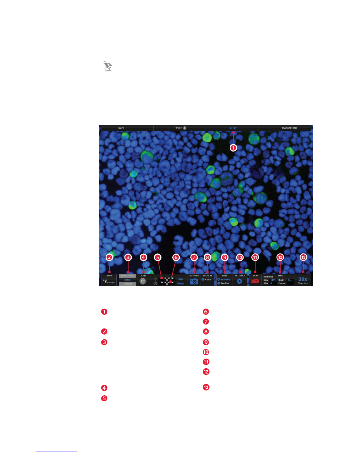
Channel Indicator Bar with the
Active Channel highlighted
Login Button
Control Bar Tabs
• Find & Focus
• Actual – Exposure Time Slider
• Overlay – Overlay Color Dialog
Light ON/OFF
Illumination Slider
8
Box
Figure 3 UI Controls Reference
Exposure Time Slider
Image Capture Button
Color Option
Scalebar/Toolbar Options
Settings Control Button
Save Image Button
Info Display Bar
Selected Objective
EVOS
®
FL and EVOS® FL Color User Guide

Software Glossary
Channel Indicator Bar
Login Button
Control Bar Tabs
Light ON/OFF Button
Illumination Slider
Exposure Time Slider
Image Capture Button
Color Display
Scalebar/Toolbar
Options
The channel indicator bar highlights the active channel (i.e., the light channel that
is currently selected).
The Login button allows for logging in and creating or changing user profiles.
This button also displays the current user profile (for example, “Guest”).
Find & Focus
Use the Find & Focus tab to view the sample with either transmitted light (to
minimize photobleaching) or fluorescence, and to acquire images. This feature
displays 10 frames per second for focusing and capturing images at longerexposure, high-quality settings.
Actual
Use the Actual tab with fluorescence channels to view the image at the actual
exposure time used for high quality image capture. With Actual tab selected, the
EVOS
changes, depending on the user-selected exposure time for the camera.
• Exposure Time Slider: Use this slider to manually select the exposure time
that will be used during image capture
Overlay
Use the Overlay tab to select and overlay multiple fluorescence channels as a
single multicolor image.
• Overlay Color Dialog Box: The Color Adjustment button (left control bar)
opens the Adjust Color dialog box where you can fine-tune your live image
Brightness, Contrast, Saturation, and Hue prior to capture.
Use this button to turn on the light source selected (for example, GFP).
Use this slider to adjust the illumination.
TIP: For quick adjustments, use the mouse wheel to brighten and dim.
Use to turn on the selected light source (for example, GFP).
Captures the image on the screen.
Use to add a pseudo color to your monochrome image.
Scalebar
The scalebar option is a toggle button available after an image is captured that will
display/hide the scalebar. Once displayed, the scalebar can be selected and
dragged on-screen to the desired position.
Toolbar
The toolbar option includes time lapse, transfection, count and image review tools;
click the small gray triangle to open each tool.
®
FL Imaging System responds more slowly to stage position and focus
EVOS® FL and EVOS® FL Color User Guide
9
Settings Control
Button
Opens the Settings dialog box.
Note: See “Optional Settings” (page 30) for a complete overview of the
settings.
Save Image Button
Use to save the onscreen image to a USB flash drive or network folder. The USB
icon turns from red to green once the image has been saved.
Info Display Bar
Shows the following context-sensitive data in the Find & Focus and Actual tabs:
Note: A red USB icon indicates that the current image has not been saved.
• Intensity (Max and Min)
• Ratio (Max to Min)
• Cursor position
Objective Selection
Displays the magnification of the currently selected objective.
Note: In Overlay, the info display shows the Quick Save option with the
Quick Save file name and the current objective selected.
The color camera version shows the QuickSave option instead of the info
display bar.
Field
10
EVOS
®
FL and EVOS® FL Color User Guide

Specifications
Optics
Objectives
Infinity-corrected optical system; RMS-threaded objectives with 45 mm parfocal distance
Objectives included vary per order. Contact Technical Support (see page 54) for a full list
of objectives supported.
Objective
Turret
Light Cubes
Illumination
Contrast
Methods
Condenser
Condenser
Working
Distance
Mechanical
“Glide” Stage
LCD Display
5-position; front-mounted control
Light cubes included vary per order. Specifications for our most popular light cubes are
listed below. Contact Technical Support (see page 54) for a full list of LED light cubes
supported.
• DAPI: 360 nm excitation, 447 nm emission
• GFP: 470 nm excitation, 525 nm emission
• RFP: 530 nm excitation, 593 nm emission
LED (50,000-hour life); adjustable intensity
Fluorescence and transmitted light (brightfield and phase contrast)
Includes 3-position with brightfield and phase contrast annuli
60 mm
XXY axis fine-positioning controls;
28.3 mm (1.11”) per rotation.
110 mm × 110 mm (4.3” × 4.3”) range of
motion
15” color, 1024 × 768 pixels; adjustable tilt
XXZ-axis focusing controls,
480 µm/rotation. XX-Interchangeable vessel
holders available for most common shapes
and sizes
Image
Acquisition
Camera
Captured
Images
Output Ports
Power Supply
Dimensions
Weight
Onboard microprocessor; built-in software for image acquisition via mouse control
Monochrome:
Sony ICX445 monochrome CCD,
1/3” 1280 × 960, 1.3 Megapixels
Monochrome camera:
16-bit monochrome TIFF or PNG (12-bit
dynamic range);
24-bit color TIFF or PNG; jpeg, bmp
(1280 × 960 pixels)
3 USB and 1 DVI (digital output)
AC Adapter; Input 100-240V, 50-60Hz; Output 12 VDC/4.15A
Operating height: 57.8 cm (22.75”)
Storage/transport height: 32.4 cm (12.75” )
Depth: 47.0 cm (18.5”); Width: 35.5 cm (14.0”)
15.3 kg (33.7 lbs)
Color:
Sony ICX285AQ color CCD,
2/3” 1360 × 1024, 1.4 Megapixels
Color camera:
16-bit color TIFF or PNG (12-bit dynamic
range);
24-bit color TIFF or PNG; jpeg, bmp
(1360 × 1024 pixels)
EVOS® FL and EVOS® FL Color User Guide
11
2. Installing the EVOS
Standard Items Included
Before setting up the EVOS® FL Imaging System, unpack the unit and accessories
and verify all parts are present. Contact your distributor if anything is missing.
Note: If you do not have your distributor information, contact Technical
Support (see page 54).
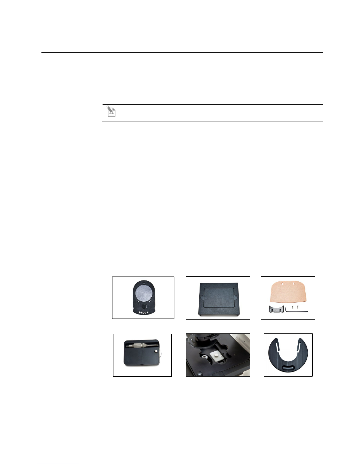
• EVOS
• Power Adapter and Power Cord
• Dust Cover
• USB Flash Drive (preconfigured with instrument documentation)
• Accessories Kit
• LED Light Cube Lock
• Condenser Shield
®
FL or EVOS® FL Color Imaging System
• Mouse
• Sliders
• Light Shield Box
• UV Shield Assembly (includes mount, shield, screws, and L-shaped hex
key)
• Light Cube Access Cover (includes LED light cube installation tool; must
be installed before using the EVOS)
®
FL Imaging System
Light Cube Access Cover
12
Sliders
Light Shield Box
LED Light Cube Lock
EVOS
UV Shield Assembly
Condenser Shield
®
FL and EVOS® FL Color User Guide
Unpacking
Note: All steps MUST be completed PRIOR to using the instrument.
To remove the instrument from the packaging, lift the instrument by grasping it
firmly with both hands under the support and place on a level surface away from
vibrations from other pieces of equipment.
®
Figure 4 Grasp under support arm with both hands to lift EVOS
Note: Be sure to set aside packaging and foam for future transport and
storage. To move or transport the instrument, the stage pin and light cube
lock must be re-installed. Always be sure the instrument is properly
cushioned and braced to prevent damage.
EVOS® FL and EVOS® FL Color User Guide
13
Operating Environment
• Allow at least 5 cm (2 in) free space at the back of the instrument to allow for
proper ventilation and to prevent overheating of electronic components.
• Operating temperature range: 4°–32°C (40°–90°F).
• Relative humidity range: 30–90%.
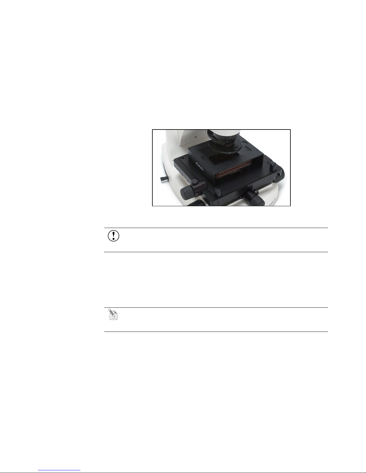
• For best image quality, avoid setting up the EVOS
direct light sources. Place the light shield box on the stage over the sample
(Figure 5, below) to reduce the effects of ambient light and improve image
quality.
®
FL Imaging System near
Figure 5 Light shield box on stage
Desktop Setup
1. Lift the EVOS® FL Imaging System as before (see page 13) and place it on the
table.
2. Tilt the LCD monitor upright.
3. Remove the stage pin, connect the power cord, mouse and, if desired,
keyboard.
Hood Setup
1. Lift the EVOS® FL Imaging System as before (see page 13) and place it inside
the hood.
2. Tilt the LCD monitor upright.
3. Remove the stage pin, connect the power cord, mouse and, if desired,
keyboard.
®
IMPORTANT! The EVOS
FL Imaging System should not be subjected to
UV sterilization. UV degrades many materials, including plastic. Damage
from UV exposure is not covered under the manufacturer’s warranty.
Note: The EVOS
®
FL Imaging System will fit in cell culture hoods that are
at least 20 ½ inches (520 mm) deep. If your cell culture hood is smaller, it
may be possible to turn the itsrument at a slight angle to fit.
14
EVOS
®
FL and EVOS® FL Color User Guide
Pins/Locks and Power Supply
Now that you have unpacked the unit and accessories and verified all parts are
present, it is time to set up the EVOS
powering on for the first time.
Stage Lock Pin
Pull firmly to remove this pin, making sure to store the stage pin for future use.
Always re-secure the mechanical stage with the stage pin before
moving/transporting the instrument.
Light Cubes
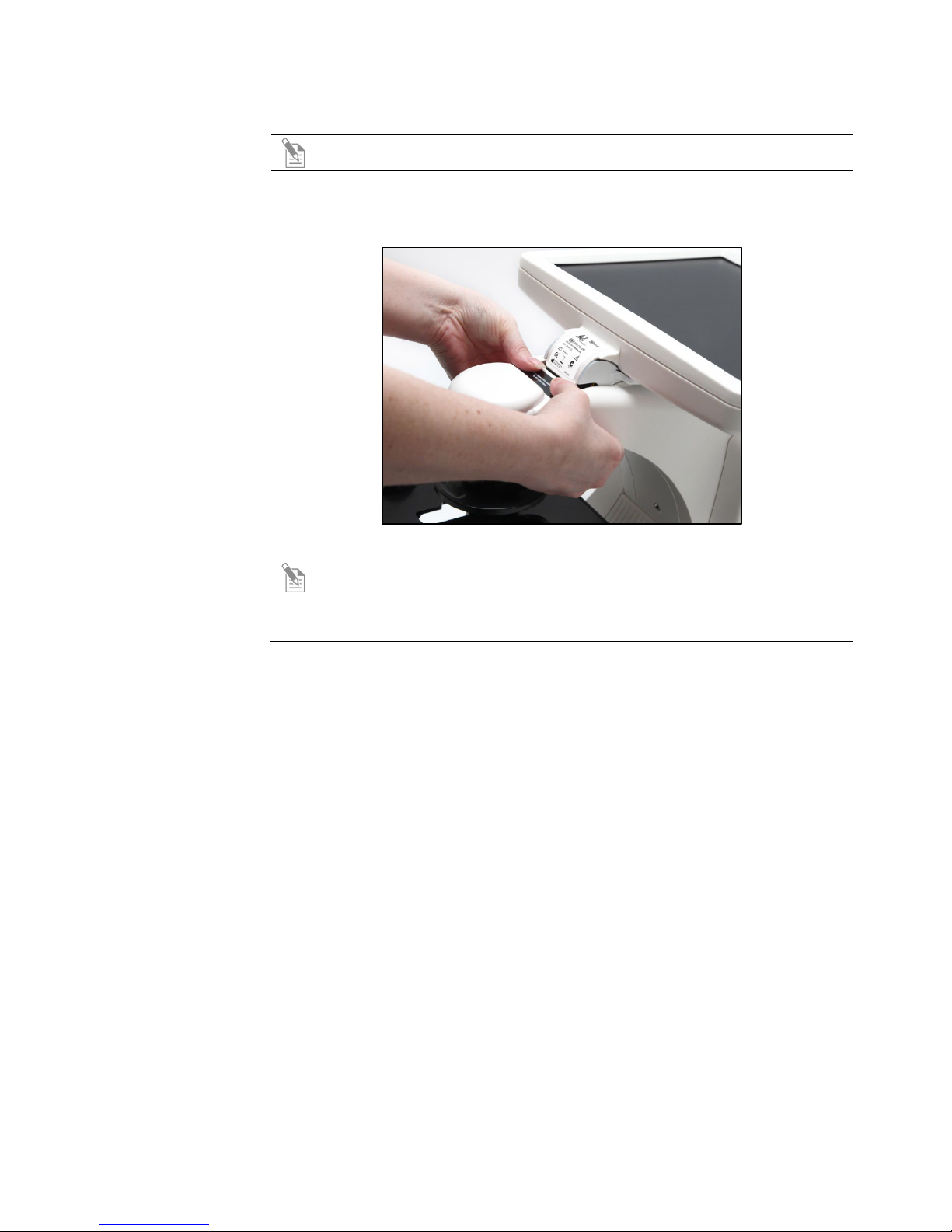
1. Move the stage back to allow access to the light cube lock, which is centered
2. Loosen the thumbscrew to remove the light cube lock, making sure to store
3. Place the light cube access cover into the opening and tighten thumbscrew.
Note: Before using the mechanical stage for the first time, you must
remove the stage lock pin from the back right-hand corner of the stage
plate.
Note: Before using the mechanical stage for the first time, you must
remove the stage lock pin from the back right-hand corner of the stage
plate. For information about adding optional LED light cubes, see
“Changing LED Light Cubes” (page 37).
under the back of the stage.
the light cube lock for future use. Always re-secure the light cube lock before
moving/transporting the instrument.
®
FL Imaging System. Follow all steps prior to
Power Supply
2. Connect the power adapter to the power jack on the right side of the
1. Verify the power switch is in the “O” (OFF) position before connecting the
IMPORTANT! Before changing light channels, ALWAYS verify the light
cube lock has been removed. Applying force to the light cube selection
lever while the lock is in place may seriously damage the mechanism. This
type of damage is not covered by the manufacturer’s warranty.
IMPORTANT! Always use the correct power supply. The power adapter
specifications appear on the serial number label (front of LCD hinge) and
in “Specifications” (page 10). Damage due to an incompatible power
adapter is not covered by warranty.
power adapter.
instrument base, attach the cord to the adapter, and plug the cord into an
outlet.
EVOS® FL and EVOS® FL Color User Guide
15
Ports and Shields
USB Ports
DVI Output Port
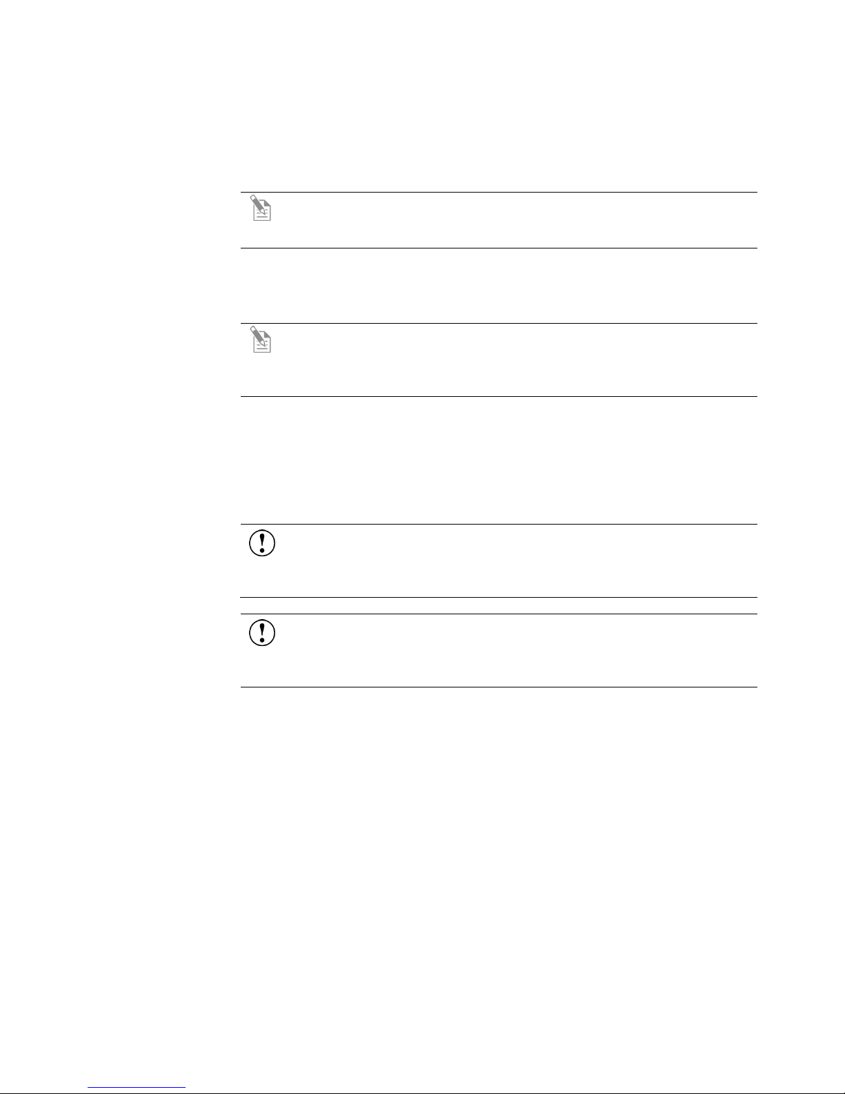
UV Shield
Plug the mouse and the USB flash drive into the USB ports located on the bottom
right of the support arm. You may also plug in a USB keyboard (not included) for
text input.
Connect the DVI cable to the DVI port on the instrument.
Secure the shield in place, as shown in Figure 6, below.
Note: A DVI port is available for output to a projector or other display
(DVI cable not included). This port produces digital output only; EVOS
Imaging System is compatible with either a DVI-D or DVI-I display.
Note: The UV Shield is provided as a safety feature and should always be
installed whenever the unit is in operation. The UV shield is removable for
access to the condenser sliders used in transmitted light mode. Simply
unhook it from the screws on the UV mount.
®
FL
Figure 6 UV shield in place
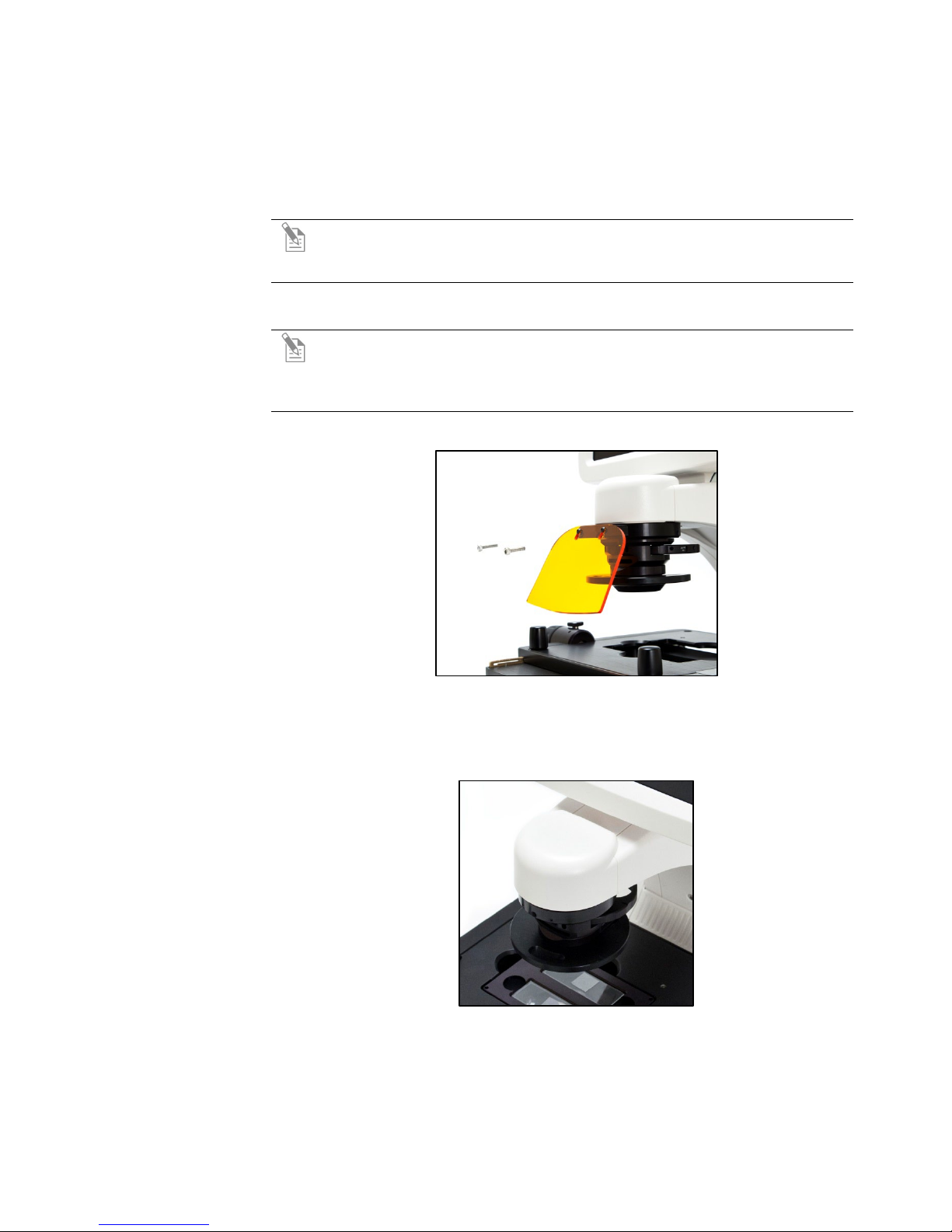
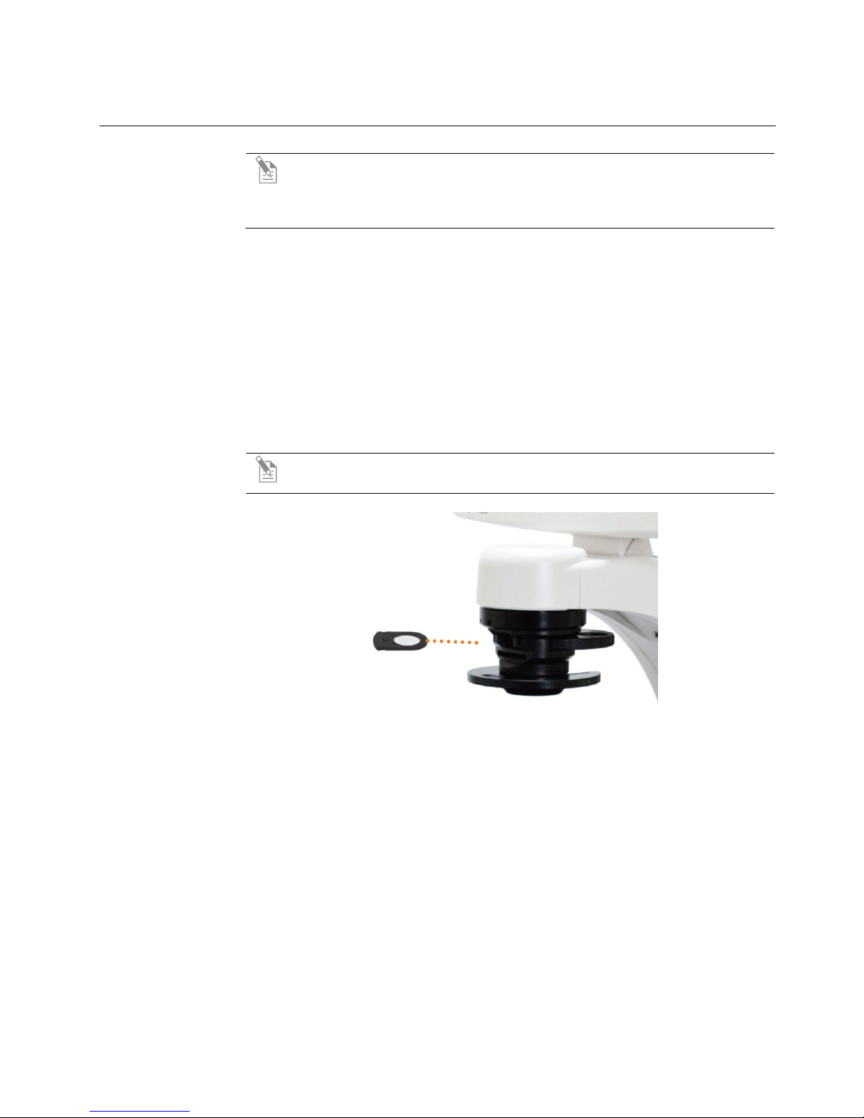
Condenser Shield
After completing all of the above steps (page 13 to 16), your instrument is ready to
The Condenser Shield is shield is pre-installed (Figure 7, below) and helps reduce
the potential effects of overhead lighting on your image.
Figure 7 Condenser Shield, removable
power on. Continue to “Basic Operations” (page 17) to get started.
16
EVOS
®
FL and EVOS® FL Color User Guide
3. Basic Operations
Brightfield/Phase Operations
1. Set the magnification using the objective selection wheel on the front of the
2. Move light cube selection lever towards you until the active channel on screen
3. Turn the phase annuli selector to the position that corresponds to the selected
4. Insert the desired condenser slider into the slot on the condenser assembly for
Note: Before using the mechanical stage for the first time, you must
remove the stage lock pin from the back right-hand corner of the stage
plate. For information about adding optional LED light cubes, see
“Changing LED Light Cubes” (page 37).
instrument.
reflects “transmitted”.
objective and contrast method.
optimal image quality.
5. Turn on illumination using the LIGHT ON button.
6. Focus the sample using the focusing knobs.
7. Adjust the illumination intensity if necessary.
Note: A variety of sliders can be inserted into the instrument condenser to
improve image quality (Figure 8).
Figure 8 Insert slider into condenser
EVOS® FL and EVOS® FL Color User Guide
17
 Loading...