

Lifestyler 831.297161 User Manual
expans
Model No. 831.297161
Serial No.
Theserialnumberisfoundinthelocation
shownbelow.Writethe serialnumberin
thespace above forfuturereference.
Serial Number
Decal
F-Q U I p M ENT
| Jill ;_i I--Ill | |oil _ il_
HELPLINE!
1-800-73d'.-d879
USER'S MANUAL
BEFORE YOU BEGIN
Thank you for selecting the LIFESTYLER" EXPANSE
600 treadmill. The EXPANSE 600 treadmill combines
advanced technology with innovative design to let you
enjoy an excellent form of cardiovascular exercise in
the convenience and privacy of your home. And when
you're not exercising, the unique EXPANSE 600 can
be folded up, requiring less than half the floor space of
other treadmills.
For your benefit, read this manual carefully before
using the treadmill. If you have additional questions,
please call our toll-free HELPLINE at 1-800-736-6879,
Monday through Saturday, 7 a.m. until 7 p.m. Central
Time (excluding holidays). To help us assist you,
please note the product model number and sedal num-
ber before calling. The model number of the treadmill
is831.297161. The sedal number can be found on a
decal attached to the treadmill (see the front cover of
this manual for the location).
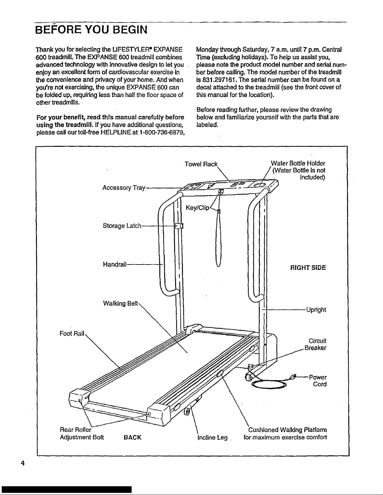
Before reading further, please review the drawing
below and familiarize yourself with the parts that are
labeled.
Accessory Tray
Towel Rack
Water Bottle Holder
not
included)
Foot Rail
Storage
Handrail
Updght
Circuit
Cord
Rear Roller
Adjustment Bolt
BACK
Incline Leg
Cushioned Walking Platform
for maximum exercise comfort
4
ASSEMBLY
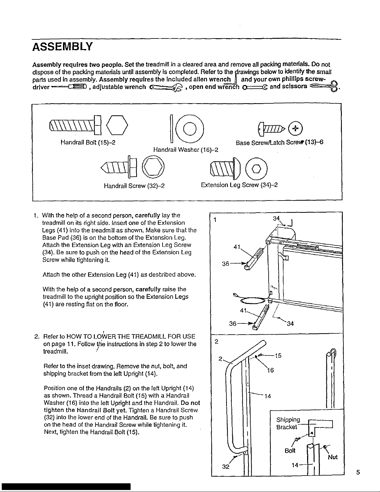
Assembly requires two people. Set the treadmill in a cleared area and remove all packing materials. Do not
dispose of the packing materials until assembly is completed. Refer to the t:lrawingsbelow to identify the small
parts used in assembly. Assembly requires the Included allen wrench__, and your own phillips screw- ,_
driver -======C_, adjustable wrench _ , open end wrench _ and scissors :=_=_.
Handrail Bolt (15)-2
Handrail Washer (16)-2
Handrail Screw (32)-2
Base Screw/Latch Screw (13)-6
Extension Leg Screw (34)-2
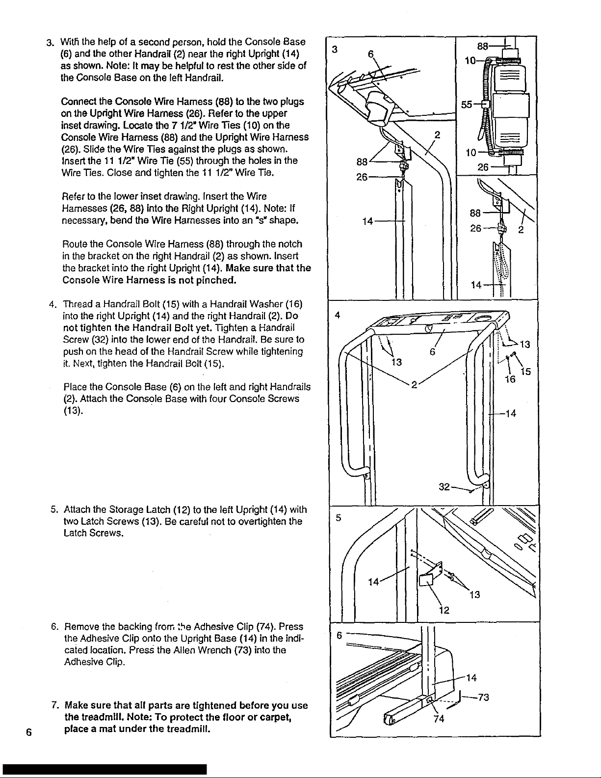
1. With the help of a second person, carefully lay the
treadmill on its dght side. insert one of the Extension
Legs (41) into the treadmill as shown. Make sure that the
Base Pad (36) is on the bottom of the Extension Leg.
Attach the Extension Leg with an Extension Leg Screw
(34). Be sure to push on the head of the Extension Leg
Screw while tightening it.
Attach the other Extension Leg (41) as desbdbed above.
With the help of a second person, carefully raise the
treadmill to the updght position so the Extension Legs
(41) are resting flat on the floor.
I
2. Refer to HOW TO LOWER THE TREADMILL FOR USE
on page 11. Follow th'e instructions in step 2 to lower the
treadmill. /
Refer to the inset drawing. Remove the nut, bolt, and
shipping bracket from the left Upright (14).
Position one of the Handrails (2) on the left Upright (14)
as shown. Thread a Handrail Bolt (15) with a Handrail
Washer (16) into the left Upright and the Handrail. Do not
tighten the Handrail Bolt yet. Tighten a Handrail Screw
(32) into the lower end of the Handrail. Be sure to push
on the head of the Handrail Screw while tightening it.
Next, tighten the Handrail Bolt (15).
41 .:
4'---.27/_
36-_y _/7 "_"34
22. _...._'_'--- 15
I II
II 1'1 Bracket .-_--J
II 14-TfI 5
6
3.
4.
With the help of a second person, hold the Console Base
(6) and the other Handrail (2) near the dght Updght (14)
as shown. Note: It may be helpful to rest the other side of
the Console Base on the left Handrail.
Connect the Console Wire Harness (88) to the two plugs
on the Upright Wire Harness (26). Refer to the upper
inset drawing. Locate the 7 1/2" Wire Ties (10) on the
Console Wire Harness (88) and the Upright Wire Harness
(26). Slide the Wire Ties against the plugs as shown.
Insert the 11 1/2" Wire Tie (55) through the holes in the
Wire Ties. Close and tighten the 11 1/2" Wire Tie.
Refer to the lower inset drawing. Insert the wire
Harnesses (26, 88) into the Right Upright (14). Note: If
necessary, bend the Wire Harnesses into an "s" shape.
Route the Console Wire Harness (88) through the notch
in the bracket on the fight Handrail (2) as shown. Insert
the bracket into the right Updght (14), Make sure that the
Console Wire Harness is not pinched.
Thread a Handrail Bolt (15) with a Handrail Washer (16)
into the right Updght (14) and the fight Handrail (2). Do
not tighten the Handrail Bolt yet. Tighten a Handrail
Screw (32) into the lower end of the Handrail. Be sure to
push on the head of the Handrail Screw while tightening
it. Next, tighten the Handrail Bolt (15).
Place the Console Base (6) on the left and right Handrails
(2). Attach the Console Base with four Console Screws
(13).
5. Attach the Storage Latch (12) to the left Upright (14) with
two Latch Screws (13). Be careful not to overtighten the
Latch Screws.
6. Remove the backing from the Adhesive Clip (74). Press
the Adhesive Clip onto the Upright Base (14) in the indi-
cated location. Press the Allen Wrench (73) into the
Adhesive Clip.
7. Make sure that all parts are tightened before you use
the treadmill. Note: To protect the floor or carpet,
place a mat under the treadmill.
3
4
2
16
13
12
74
OPERATION AND ADJUSTMENT
_'HEPERFORMANT LUBE r=WALKING BELT
Your treadmill features a walking belt coated with
PERFORMANT LUBE TM, a high-pedormance lubricant.
IMPORTANT: Never apply silicone spray or other
substances to the walking belt or the walking plat-
form. Such substances will deteriorate the walking
belt and cause excessive wear.
HOW TO PLUG IN THE POWER CORD
Your treadmill, like any other type of sophisticated
_lectronic equipment, can be sedously damaged by
sudden voltage changes in your home's power.
Voltage surges, spikes, and noise interference can
result from weather conditions or from other appliances
being turned on or off. To decrease the possibility of
your treadmill being damaged, always use a surge
suppressor with your treadmill (see drawing 1 at
the right).
Surge suppressors are sold at most hardware stores
and department stores. Use only a single-outlet surge
suppressor that is UL 1449 listed as a transient voltage
surge suppressor (TVSS). The surge suppressor must
have a UL suppressed yoltage rating of 400 volts or
less and a minimum surge dissipation of 450 joules.
The surge suppressor must be electrically rated for
120 volts AC and 15 amps.
This product must be grounded. If it should malfunc-
tion or break down, grounding provides a path of least
resistance for electric current to reduce the risk of elec-
tric shock. This product is equipped with a cord having
an equipment-grounding conductor and a grounding
plug. Plug the power cord into a surge suppressor,
and plug the surge suppressor into an appropriate
_utlet that is properly installed and grounded in
_ccordance with all local codes and ordinances.
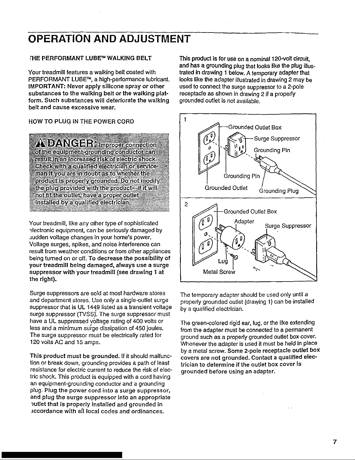
This product is for use on a nominal 120-volt circuit,
and has a grounding plug that looks like the plug illus-
trated in drawing 1 below. A temporary adapter that
looks like the adapter illustratedin drawing 2 may be
used to connect the surge suppressor to a 2-pole
receptacle as shown in drawing 2 if a pmpedy
grounded outlet is not available.
'_.. Grounding Pin
Grounding pn__
Grounded Outlet Grounding Plug"_
2 _l_-Grounded Outlet Box
&_,,_da.__, pter Surge Suppressor
I
The temporary adapter should be used only until a
properly grounded outlet (drawing 1) can be installed
by a qualified electrician.
The green-colored rigid ear, lug, or the like extending
from the adapter must be connected to a permanent
ground such as a propedy grounded outlet box cover.
Whenever the adapter is used it must be held in place
by a metal screw. Some 2-pole receptacle outlet box
covers are not grounded. Contact a qualified elec-
trician to determine if the outlet box cover Is
grounded before using an adapter.
7
 Loading...