

Lifestand LSCT Service Manual
LSCT
Maintenance manual
Item N° 326617
Revision A
Date 25/06/2015
Page 1 of 93
LSCT
Service manual:
ENGLISH

LSCT
Maintenance manual
Item N° 326617
Revision A
Date 25/06/2015
Page 2 of 93
CONTACT LIFESTAND
The company Lifestand, which is part of the Permobil Group, is responsible for maintenance
and sales services undertaken by its local importers and distributors.
Do not hesitate to contact us to find the contact details of the point of sale and after sales
service closest to your domicile.
Registered office of the Permobil Group
Permobil AB
Box 120
861 23 Timrä
SWEDEN
Tel. +46 (0) 60 59 59 00
Fax: +46 (0) 60 57 52 50
E-mail: info@permobil.se
Lifestand Permobil Group
5 Rue Clément Ader
69740 Genas
FRANCE
Tel. +33 (0)4 37 26 27 28
Fax: +33 (0)4 37 26 27 29
E-mail: info@permobil.com
Please consult the user manual and/or the pre-sales information for any information not
mentioned in this manual, which can be downloaded from the Permobil & Lifestand websites or
contact the closest Permobil / Lifestand centre.
LSCT
Maintenance manual
Item N° 326617
Revision A
Date 25/06/2015
Page 3 of 93
Contents
CONTACT LIFESTAND ............................................................................................................. 2
INFORMATION .......................................................................................................................... 4
REPAIRS .............................................................................................................................. 5-54
SETTINGS .......................................................................................................................... 55-72
WIRING ............................................................................................................................... 73-80
TROUBLESHOOTING ........................................................................................................ 81-93
GENERAL WARNINGS FOR ANY INTERVENTION CARRIED OUT ON THE CHAIR:
Before any repairs and/or modifications on the chair, analyse the intervention points so
that you can put the chair back together again.
When dismantling one or more components, always be careful of the weight and/or the
weight of the component(s) which it supports and/or holds.
Before any mechanical intervention on the chair, remove the fuse from the chair (see
section «Fuse»).
Put some medium threadlock on the screws which are not locked with a brake nut and/or
which are not adjustment screws.
LSCT
Maintenance manual
Item N° 326617
Revision A
Date 25/06/2015
Page 4 of 93
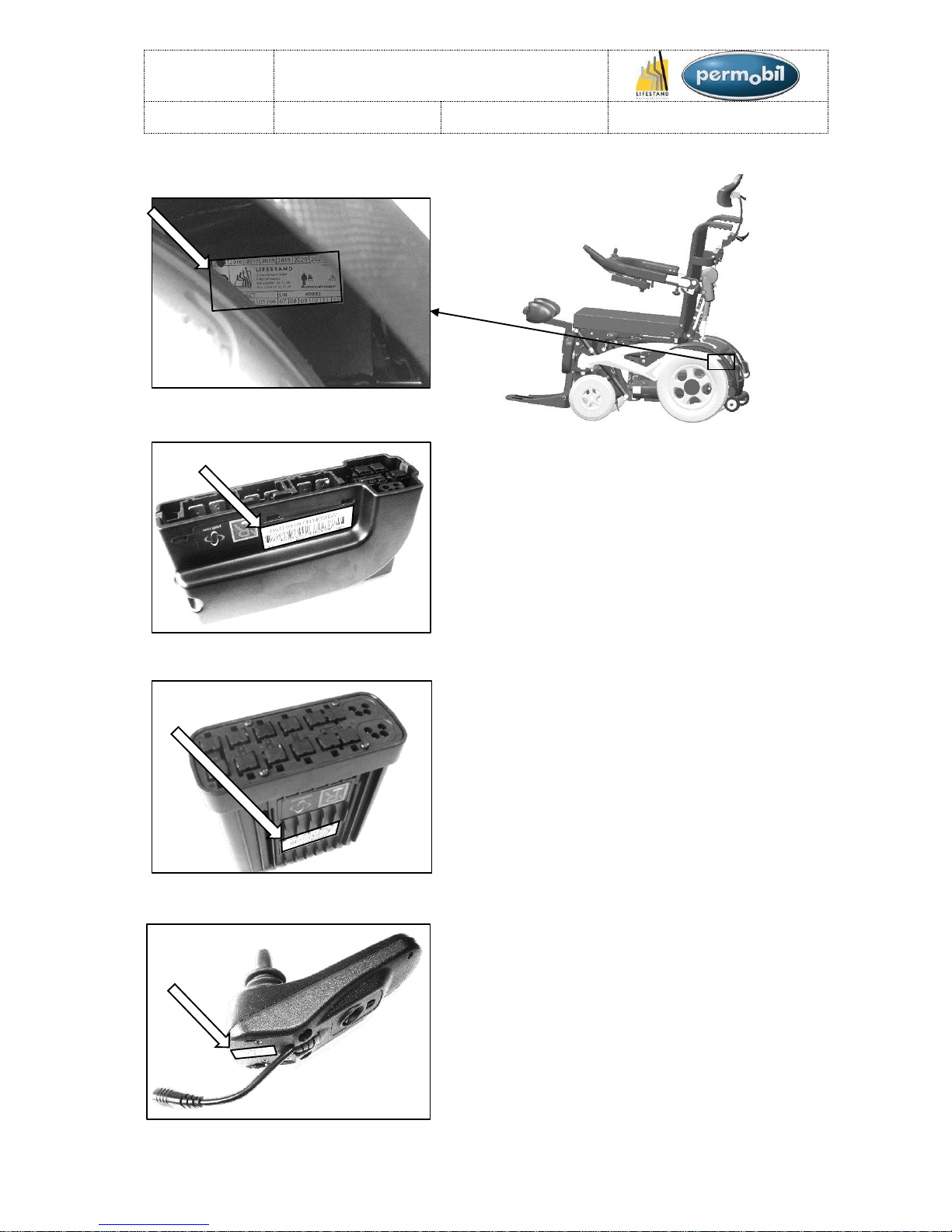
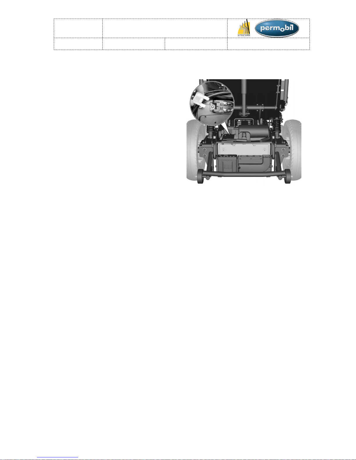
NAME PLATES:
FRAME:
POWER MODULE R-NET:
(Dismantle the back cover to gain access to the
Power module R-NET; see section «Back cover».)
ISM R-NET:
(Dismantle the back cover to gain access to the
ISM R-NET; see section «Back cover».)
CONTROL BOX R-NET:
INFORMATION
Figure 1
Figure 2
Figure 3
Figure 4

LSCT
Maintenance manual
Item N° 326617
Revision A
Date 25/06/2015
Page 5 of 93
REPAIRS
BACK COVER: ........................................................................................................................... 7
FUSE: ........................................................................................................................................ 8
UNDERRIDE GUARD AND ANTITIPPER WHEEL: ................................................................... 9
ISM AND/OR POWER MODULE: ........................................................................................... 10
BATTERIES (1/2): .................................................................................................................. 111
BATTERIES (2/2): .................................................................................................................... 12
REAR WHEELS (1/2) : ................................................................ ............................................ 13
REAR WHEELS (2/2) : ................................................................ ............................................ 14
FRONT WHEELS (1/2): ............................................................................................................ 15
FRONT WHEELS (2/2): ............................................................................................................ 16
FRONT WHEEL BEARINGS (1/2): ........................................................................................... 17
FRONT WHEEL BEARINGS (2/2): ........................................................................................... 18
FRAME (1/2): ........................................................................................................................... 19
FRAME (2/2): ........................................................................................................................... 20
SEAT TILT: .............................................................................................................................. 21
GUIDE RAILS ....................................................................................................................... 21
SEAT TILT ACTUATOR: ....................................................................................................... 22
FRONT TRANSLATION GUIDING: ....................................................................................... 23
SEAT STOP: ............................................................................................................................ 24
STANDING STOP: ................................................................................................................... 25
BACKREST ACTUATOR (1/2): ................................................................................................ 26
BACKREST ACTUATOR (2/2): ................................................................................................ 27
STANDING ACTUATOR (1/2): ................................................................................................ . 28
STANDING ACTUATOR (2/2): ................................................................................................ . 29
LEGREST: ............................................................................................................................... 30
LEGREST ACTUATOR (1/2): ................................................................................................... 31
LEGREST ACTUATOR (2/2): ................................................................................................... 32
LEGREST GUIDE RAIL (1/2): .................................................................................................. 33

LSCT
Maintenance manual
Item N° 326617
Revision A
Date 25/06/2015
Page 6 of 93
LEGREST GUIDE RAIL (2/2): .................................................................................................. 34
LEGREST COMPENSATION STRAP: ..................................................................................... 35
LEGREST COMPENSATION STRAP ROLLERS: .................................................................... 36
LEGREST LOWER BEARING: ................................................................................................. 37
SHOCK ABSORBERS (1/2): .................................................................................................... 38
SHOCK ABSORBERS (2/2): .................................................................................................... 39
FRONT LIGHTS: ...................................................................................................................... 40
REAR LIGHTS: ........................................................................................................................ 41
MOTORS (1/2): ........................................................................................................................ 42
MOTORS (2/2): ........................................................................................................................ 43
UNITRACK RAILS: ................................................................................................................... 44
ARMRESTS (1/2): .................................................................................................................... 45
ARMRESTS (2/2): .................................................................................................................... 46
SEAT CUSHION : .................................................................................................................... 47
SEAT PLATES: ........................................................................................................................ 48
BACKREST COVERS: ............................................................................................................. 49
BACKREST STRAPS (1/2): ..................................................................................................... 50
BACKREST STRAPS (2/2): ..................................................................................................... 51
BACKREST (1/2): ..................................................................................................................... 52
BACKREST (2/2): ..................................................................................................................... 53
LSCT
Maintenance manual
Item N° 326617
Revision A
Date 25/06/2015
Page 7 of 93
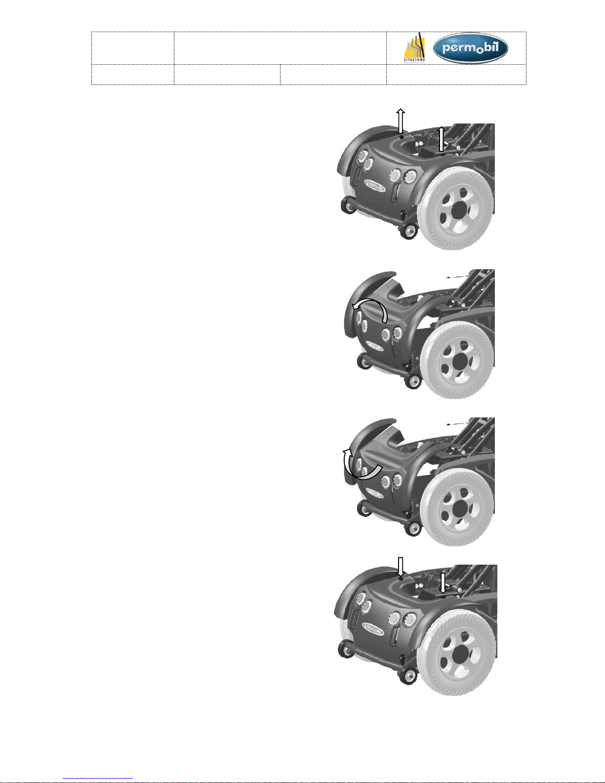
BACK COVER:
Dismantling:
1. Unscrew the two handles. (Place the
chair in standing position to facilitate
access to the handles). (See figure 5)
2. Carefully pull the back cover backwards
and disconnect the lights and indicators
before removing it completely. (Pay
attention to the way in which the back
cover is removed). (See figure 6)
Figure 5
Figure 6
Assembly:
Assemble in the reverse order.
1. Reconnect the lights and indicators (See
section «Electrical circuit diagram».
2. Replace the back cover by making the
opposite movement of removing it. (See
figure 7)
3. Replace and re-tighten the two handles.
(See figure 8)
Figure 7
Figure 8
REPAIRS:
LSCT
Maintenance manual
Item N° 326617
Revision A
Date 25/06/2015
Page 8 of 93
FUSE:
1. Place the chair in standing position.
2. Take off the back cover (See section
«Back cover»).
3. Remove the protective housing of the
fuse holder. (See figure 9)
4. Remove the fuse. (See figure 9)
5. Insert the new fuse.
6. Replace the protective housing of the
fuse holder.
7. Put back the back cover (See section
«Back cover»).
Figure 9
REPAIRS:

LSCT
Maintenance manual
Item N° 326617
Revision A
Date 25/06/2015
Page 9 of 93
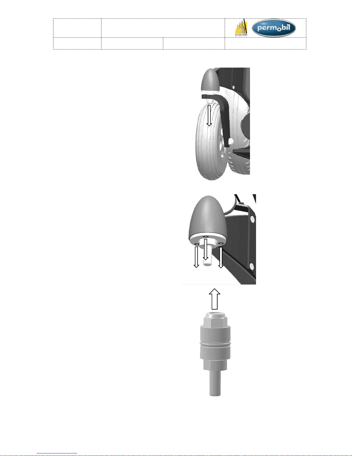
UNDERRIDE GUARD AND ANTITIPPER WHEELS:
Dismantling:
1. Take off the back cover (See section
«Back cover»).
2. Take off the 4 nuts and washers then
remove the underride guard. (See figure
10)
Figure 10
3. Remove the nut cap and take off the nut
that is behind. (See figure 11)
4. Replace the antitipper wheel(s).
Figure 11
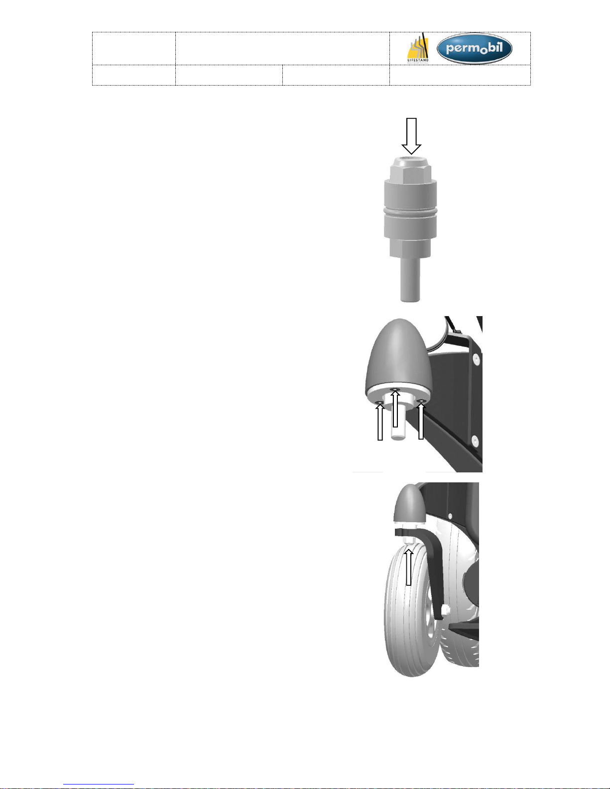
Assembly:
Assemble in the reverse order.
1. Re-tighten the nuts on the antitipper
wheels (adjust the tightening so that the
wheels can rotate freely). (See figure 12)
2. Replace the nut cap. (See figure 12)
Figure 12
3. Put back the underride guard with the 4
washers and the 4 nuts. (Tightening
torque: 27N.m). (See figure 13)
4. Put back the back cover (See section
«Back cover»).
Figure 13
REPAIRS:
LSCT
Maintenance manual
Item N° 326617
Revision A
Date 25/06/2015
Page 10 of 93
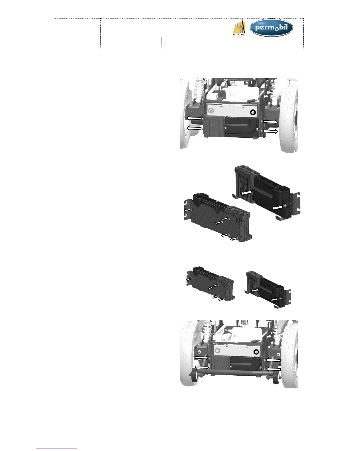
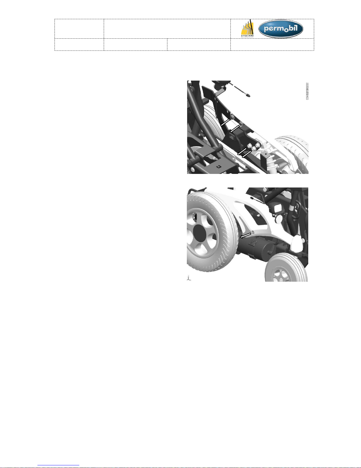
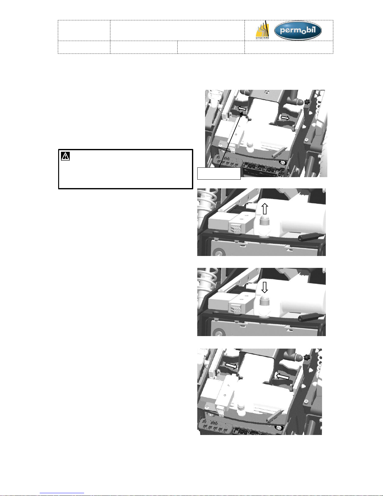
ISM AND/OR POWER MODULE:
Dismantling:
1. Remove the back cover (see section
«Back cover»).
2. Remove the underride guard (see section
«Underride guard and antitipper wheels).
3. Unscrew the 4 screws. (See figure 14)
4. Disconnect all the cables connected to
the ISM or the Power Module (noting their
position).
5. Remove the closing plate and unscrew
the ISM and/or the Power Module. (See
figure 15 & 16)
Figure 14
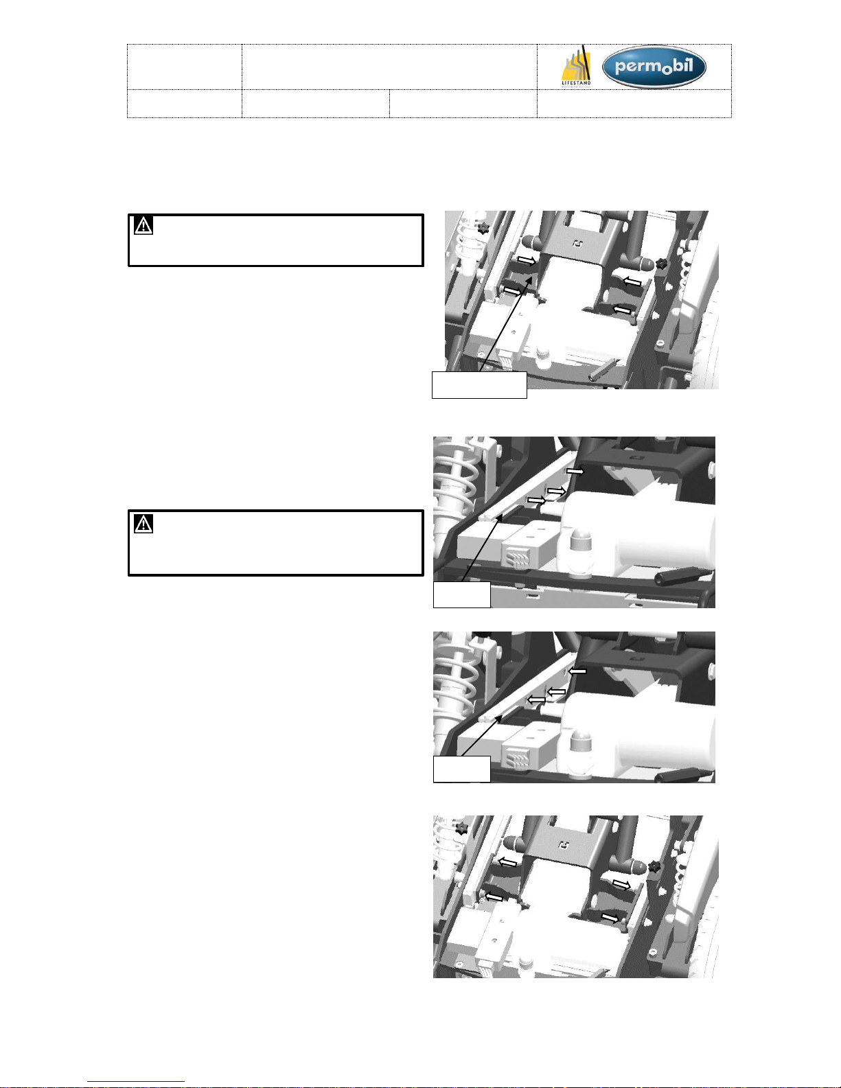
Assembly:
Assemble in the reverse order.
1. Reattach the Power Module and/or the
ISM. (See figure 17 & 18)
2. Reposition the closing plate.
3. Re-tighten the 4 screws (Tightening
torque: 11.1N.m). (See figure 19)
4. Put back the underride guard (Tightening
torque: 27N.m).
5. Reconnect the various connectors on the
power module and/or the ISM (See
section «Electrical circuit diagram» and
«Chair cabling»).
6. Put back the back cover (see section
«Back cover»).
Figure 19
REPAIRS:
Figure 15
Figure 16
Figure 18
Figure 17
LSCT
Maintenance manual
Item N° 326617
Revision A
Date 25/06/2015
Page 11 of 93
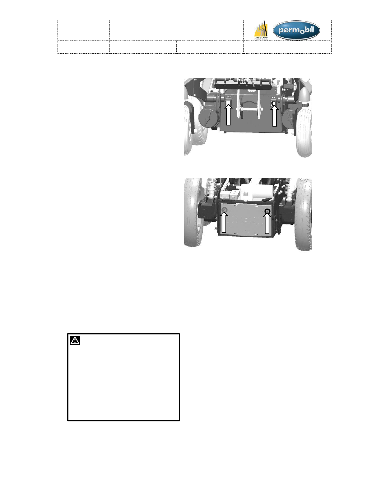
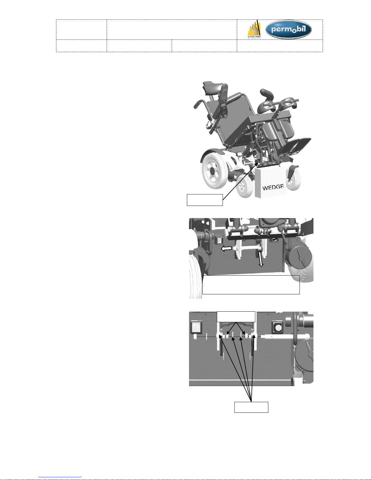
BATTERIES (1/2):
Dismantling:
1. Tilt completely the seat of the chair.
2. Remove the back cover (See section
«Back cover»).
3. Remove the fuse (See section
«fuse»)
4. Remove the underride guard (See
section «Underride guard and
antitipper wheels»).
5. Remove the closing plate (Step 3
section «ISM and/or Power Module»).
6. Unplug the motors and the power
cables from the power module (See
section «Electrical circuit diagram»).
7. Flip up the plate with the Ism and the
power module.
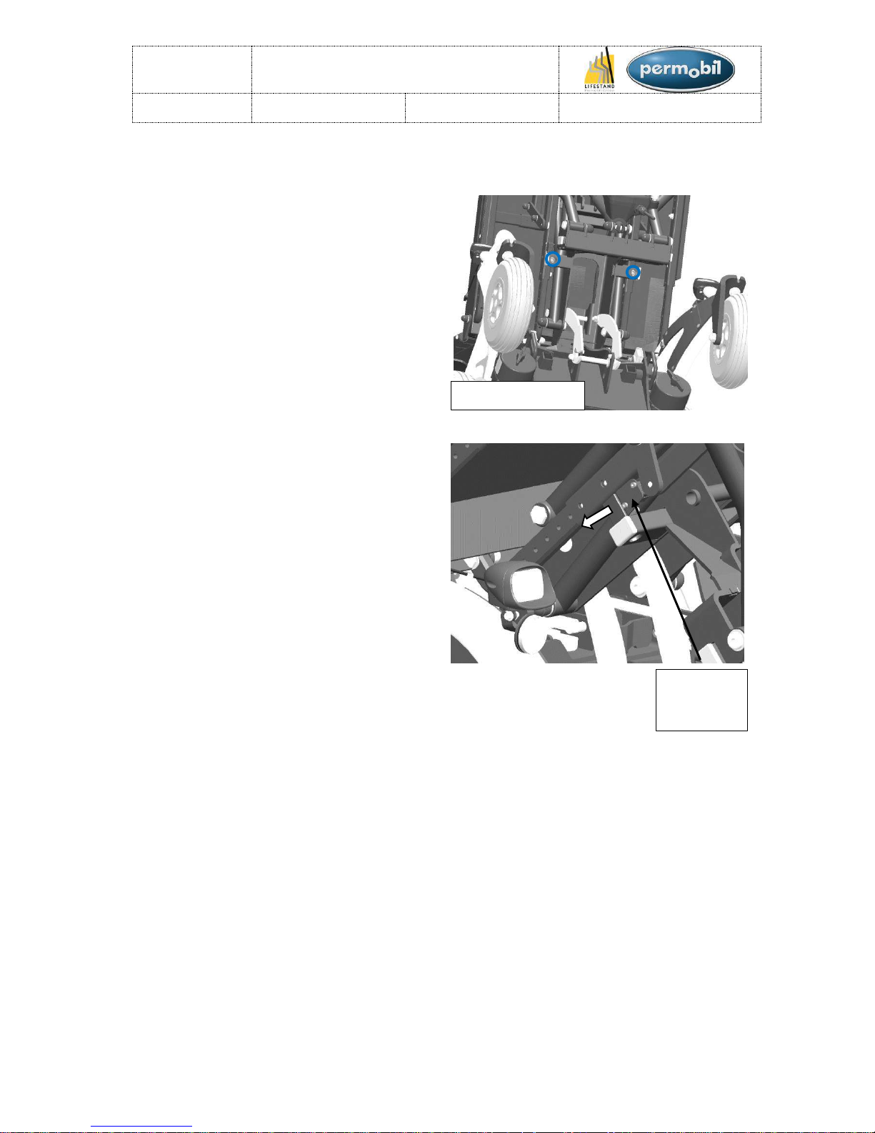
8. Unscrew the two screws on the front
battery and unscrew the two screws
on the rear battery. (See figure 20 &
21)
9. Remove the rear battery with the
assistance of its handles (WARNING:
do not place the battery connectors in
contact with anything else and be
careful to not damage the cables).
10. Then remove the second battery.
WARNING !
Be careful when using metal tools or
objects close to the batteries, a shortcircuit can easily cause an explosion.
Always use gloves and safety
glasses.
Remember that the batteries are
heavy and they must be handled
extremely carefully.
Figure 20
Figure 21
REPAIRS:
LSCT
Maintenance manual
Item N° 326617
Revision A
Date 25/06/2015
Page 12 of 93
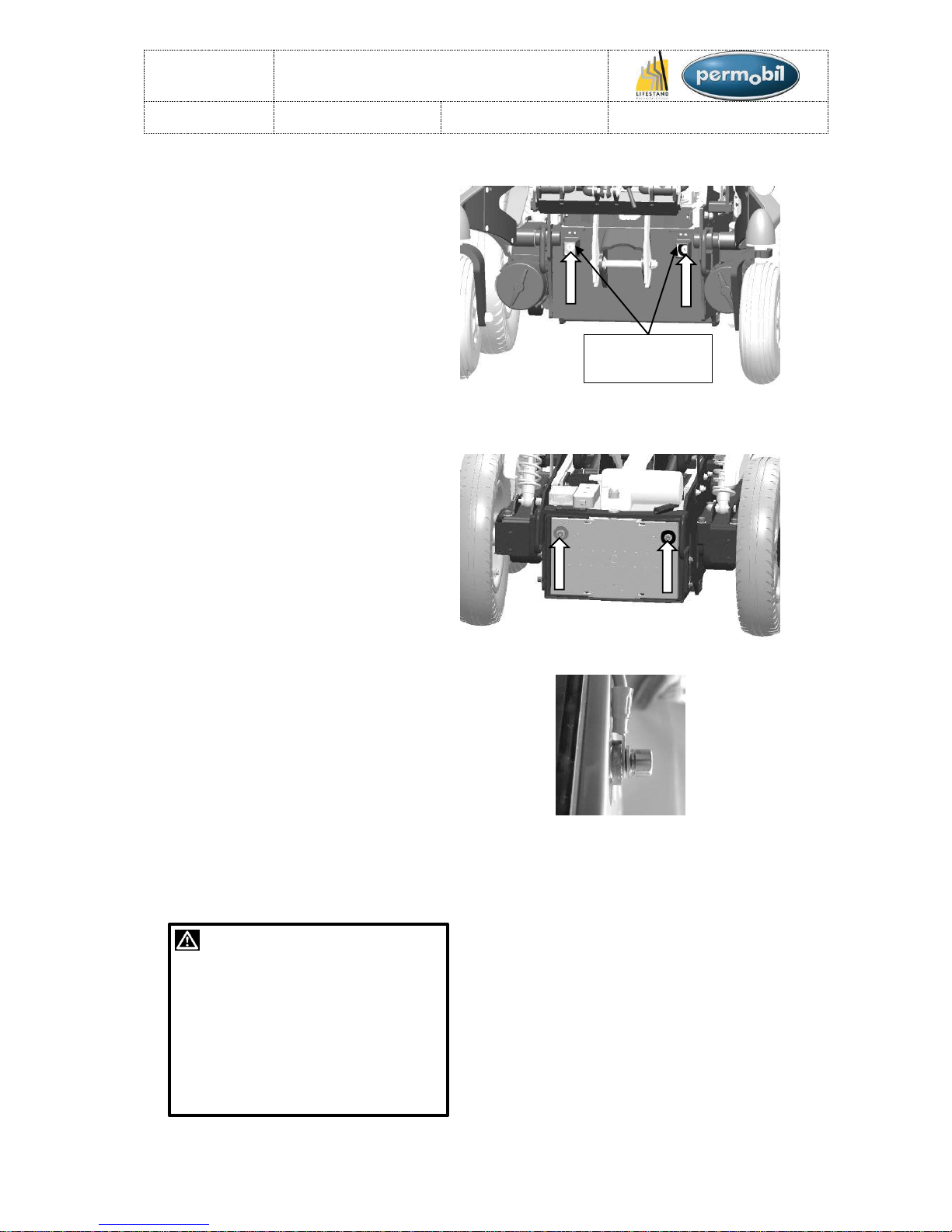
BATTERIES (2/2):
Assembly:
Assemble in the reverse order.
1. Insert the front battery ensuring that
the connector guards are in the right
position. (Warning, the battery
connectors must under no
circumstances come into contact with
any other components).
2. Reconnect the wire bundles to the
front battery and tightening the
screws (Be careful to the orientation
of the connector (see Figure 22 and
23-b)) (Tightening torque: 11.1N.m).
(See section «Electrical circuit
diagram»).
3. Insert the second battery and
reconnect the wire bundles to the
rear battery and tighten the screws
(Be careful to the orientation of the
connector (see Figure 23 and 23-b))
(Tightening torque: 11.1N.m). (See
section «Electrical circuit diagram»)
4. Put back the closing plate (See step
2 and 3 section «ISM and/or Power
Module»).
5. Put back the underride guard (See
section «Underride guard and
antitipper wheels»).
6. Plug back the motors and power
cables on the power module (See
section «Electrical circuit diagram»)
7. Put back the fuse (See section
«Fuse»)
8. Put back the back cover (See section
«Back cover»).
WARNING !
Be careful when using metal tools or
objects close to the batteries, a shortcircuit can easily cause an explosion.
Always use gloves and safety
glasses.Remember that the batteries
are heavy and they must be handled
extremely carefully.
Figure 22
Figure 23-a
Figure 23-b
Connector
guards
REPAIRS:
LSCT
Maintenance manual
Item N° 326617
Revision A
Date 25/06/2015
Page 13 of 93
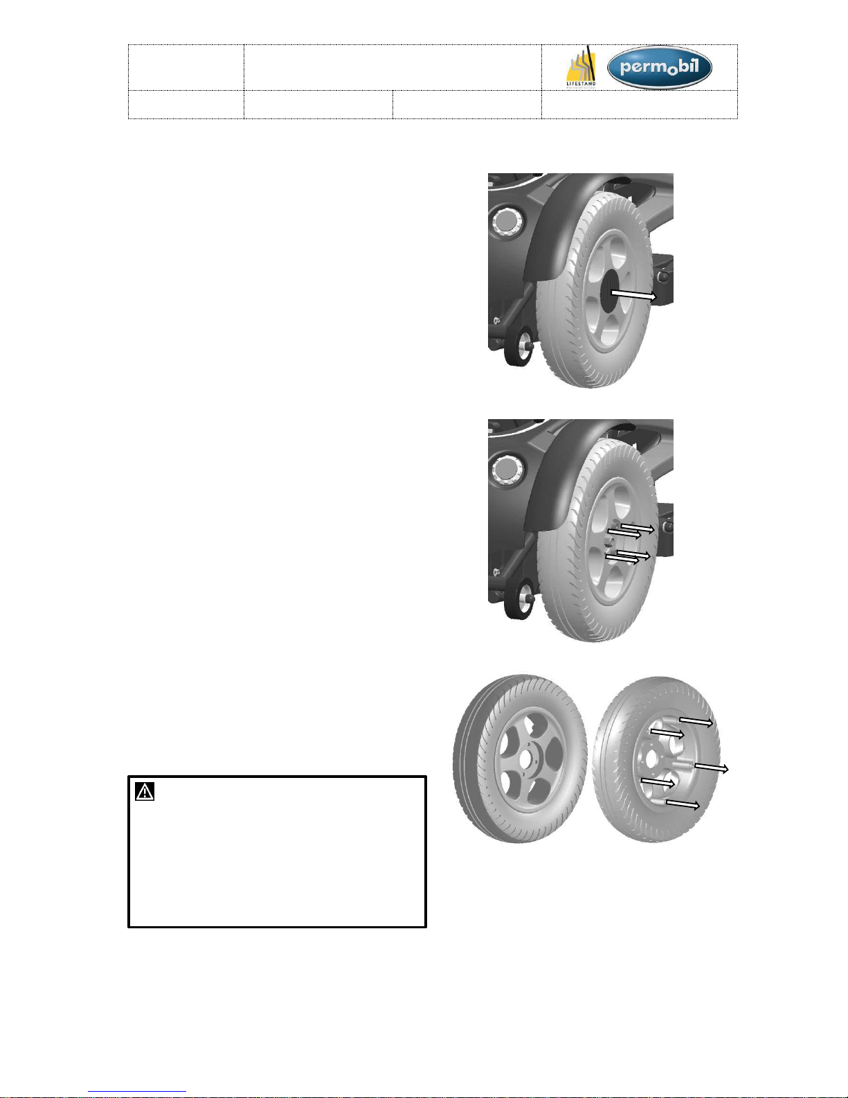
REAR WHEELS (1/2):
Dismantling:
1. Place the chair on wedges so that the
rear wheels are no longer in contact with
the ground. (Leave the motor in the
«ENGAGED» position).
2. Remove the plastic cover using a flathead screwdriver (be careful not to
damage the rim). (See figure 24).
Figure 24
3. Remove the 4 cylindrical head screws.
(See figure 25).
4. Remove the wheel.
Figure 25
5. To change the tyre, inner tube or the solid
tyre, remove the 5 screws (inside edge of
the wheel) and separate the interior
section from the outer section of the rim.
(See figure 27).
WARNING !
The tyre pressure recommended for the rear
tyres is between 2.5 and 3 bar. Over-inflation
can cause the tyre to explode. Underinflation will lead to stability and handling
problems, as well as premature wear and
tear. It is important to check the tyre pressure
regularly.
REPAIRS:
Figure 27
Figure 26
LSCT
Maintenance manual
Item N° 326617
Revision A
Date 25/06/2015
Page 14 of 93
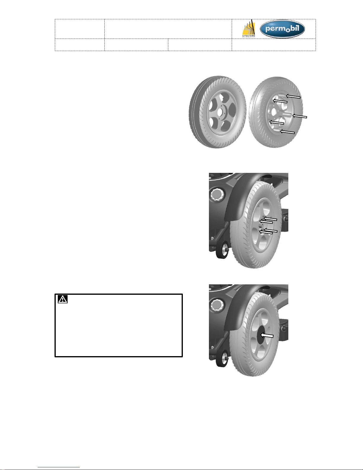
REAR WHEELS (2/2):
Assembly:
Assemble in the reverse order.
1. Reassemble the rear wheel and re-tighten
the 5 screws (Tightening torque: 27N.m)
(See figure 29).
2. Attach the wheel onto the hub with the 4
cylindrical head screws. (Tightening
torque: 27N.m) (See figure 30).
3. Replace the plastic cover. (See figure 31)
WARNING !
The tyre pressure recommended for the rear
tyres is between 2.5 and 3 bar. Over-inflation
can cause the tyre to explode. Underinflation will lead to stability and handling
problems, as well as premature wear and
tear. It is important to check the tyre pressure
regularly.
REPAIRS:
Figure 28
Figure 29
Figure 30
Figure 31
LSCT
Maintenance manual
Item N° 326617
Revision A
Date 25/06/2015
Page 15 of 93
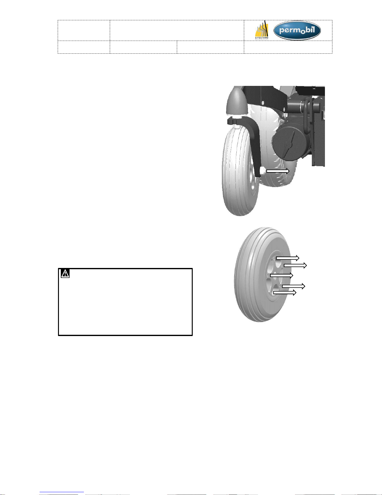
FRONT WHEELS (1/2):
Dismantling:
1. Place the chair on wedges so that the
front wheels do not touch the ground.
2. Remove the nut and take off the wheel.
(See figure 32)
3. To change the tyre or inner tube, remove
the 5 screws then separate the interior
section from the outer section of the rim.
(See figure 33)
WARNING !
The tyre pressure recommended for the front
tyres is between 2.5 and 3 bar. Over-inflation
can cause the tyre to explode and premature
wear and tear. Under-inflation will lead to
stability and handling problems, as well as
premature wear and tear. It is important to
check the tyre pressure regularly.
REPAIRS:
Figure 32
Figure 33
LSCT
Maintenance manual
Item N° 326617
Revision A
Date 25/06/2015
Page 16 of 93
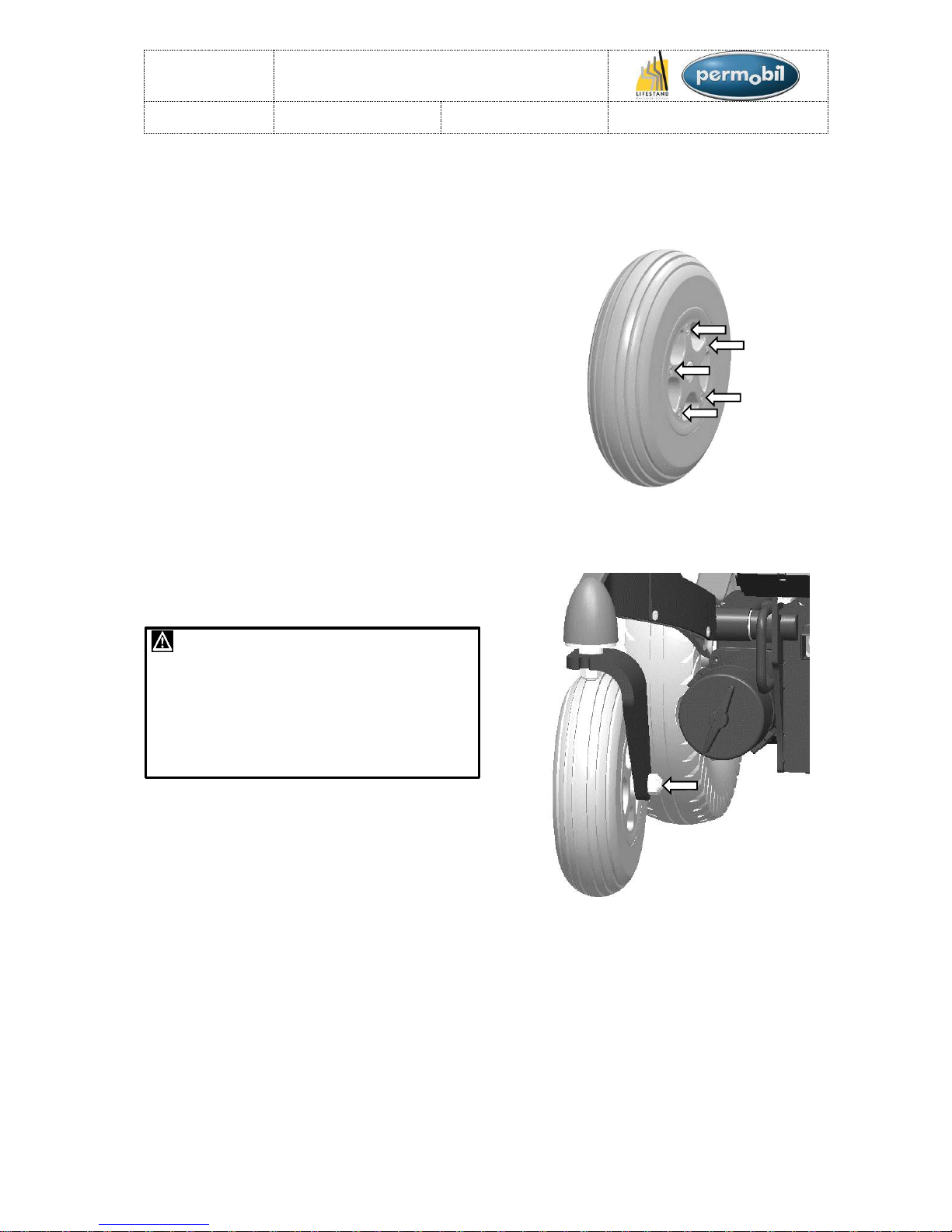
FRONT WHEELS (2/2):
Assembly:
Assemble in the reverse order.
1. Reassemble the front wheel and retighten the 5 screws (tightening torque:
27N.m) (See figure 34)
2. Put the front wheel back and tighten the
nut (Tightening torque: 92N.m). (See
figure 35)
WARNING !
The tyre pressure recommended for the front
tyres is between 2.5 and 3 bar. Over-inflation
can cause the tyre to explode. Underinflation will lead to stability and handling
problems. It is important to check the tyre
pressure regularly.
REPAIRS:
Figure 34
Figure 35
LSCT
Maintenance manual
Item N° 326617
Revision A
Date 25/06/2015
Page 17 of 93
FRONT WHEEL BEARINGS (1/2):
Dismantling:
1. Place the chair on wedges so that the
front wheels do not touch the ground.
2. Remove the nut and take off the fork +
wheel set. (See figure 36)
3. Remove the 3 screws, take off the washer
then remove the axle + bearing set. (See
figure 37)
4. Remove the nut then replace the
bearings and/or the friction disc set. (See
figure 38)
REPAIRS:
Figure 36
Figure 37
Figure 38
LSCT
Maintenance manual
Item N° 326617
Revision A
Date 25/06/2015
Page 18 of 93
FRONT WHEEL BEARINGS (2/2):
Assembly:
Assemble in the reverse order.
1. Re-tighten the nut (Tightening torque:
148N.m) (See figure 39)
2. Insert the axle + bearing set into the
frame housing (place a bit of grease onto
the bearings and the O-ring to make it
easier to insert into the frame).
3. Place the washer into position then
tighten the 3 countersunk head screws.
(Tightening torque: 3.22N.m). (See figure
40)
4. Reattach the fork + wheel set with the nut
and the washer (Tightening torque:
92N.m). (See figure 41)
REPAIRS:
Figure 39
Figure 40
Figure 41
LSCT
Maintenance manual
Item N° 326617
Revision A
Date 25/06/2015
Page 19 of 93
FRAME (1/2):
Dismantling:
1. Place the chair in standing position.
2. Take off the back cover (See section
«Back cover»).
3. Remove the front light (see section «Front
lights»).
4. Remove the 5 screws which hold the
frame. (See figure 42 & 43)
REPAIRS:
Figure 42
Figure 43

LSCT
Maintenance manual
Item N° 326617
Revision A
Date 25/06/2015
Page 20 of 93
FRAME (2/2):
Assembly:
Assemble in the reverse order.
1. Position the frame in front of its attaching
holes.
2. Pre-tighten the 4 interior screws (only a
few turns of the thread) (See figure 44)
3. Pre-tighten the external screw. (See
figure 45)
4. Finish tightening the 4 interior screws
(Tightening torque: 27N.m). (See figure
44)
5. Finish tightening the external screw
(Tightening torque: 53N.m). (See figure
45)
6. Replace the front light (See section
«Front lights»).
7. Put back the back cover (See section
«Back cover»).
REPAIRS:
Figure 44
Figure 45
LSCT
Maintenance manual
Item N° 326617
Revision A
Date 25/06/2015
Page 21 of 93
SEAT TILT:
GUIDE RAILS
Dismantling:
WARNING !
There must be no load on the wheelchair
1. Place the chair in standing position.
2. Take off the back cover (See section
«Back cover»).
3. Remove the 4 screws on the «trolley».
(See figure 46)
4. Place the trolley carefully on the batteries.
5. Remove the 5 screws fixed to the rail.
(move the rail pad to gain access to all
the screws). (See figure 47)
WARNING !
When removing the rails, hold the seat of the
chair to stop it tipping over.
6. Replace the rail.
Assembly:
Assemble in the reverse order.
1. Attach the rail by tightening the 5
countersunk head screws (Tightening
torque: 11.1N.m). (Move the pad to gain
access to all the screws). (See figure 48)
2. Reattach the trolley by tightening the 4
cylindrical head screws on the rail pads.
(Tightening torque: 9.8N.m). (See figure
49)
3. Replace the back cover (See section
«Back cover»).
REPAIRS:
«Trolley»
Pad
Pad
Figure 46
Figure 47
Figure 48
Figure 49
LSCT
Maintenance manual
Item N° 326617
Revision A
Date 25/06/2015
Page 22 of 93
SEAT TILT:
SEAT TILT ACTUATOR:
Dismantling:
1. Place the chair in standing position
2. Take off the back cover (See section
«Back cover»).
3. Remove the 2 axles from the «trolley».
(See figure 50)
WARNING !
When removing the two axles from the
trolley, hold the seat of the chair to stop it
tipping over.
4. Remove the nut cap and unscrew the nut.
(See figure 51)
5. Disconnect the actuator from the ISM.
6. Remove the actuator by lifting it up then
pulling it backwards.
Assembly:
Assemble in the reverse order.
1. Replace the actuator.
2. Insert the washer on the axle attaching
the actuator and pre-tighten the nut. (See
figure 52)
3. Reattach the 2 axles of the trolley
(Tightening torque: 17N.m). (See figure
53)
4. Finish tightening the rear fastening of the
actuator. (Tightening torque: 53N.m) (See
figure 52)
5. Reconnect the actuator to the ISM (See
section «Electrical circuit diagram»).
6. Put back the back cover (See section
«Back cover»).
REPAIRS:
«Trolley»
Figure 50
Figure 51
Figure 52
Figure 53
LSCT
Maintenance manual
Item N° 326617
Revision A
Date 25/06/2015
Page 23 of 93
SEAT TILT:
FRONT TRANSLATION GUIDING:
Dismantling:
1. Tilt the seat backwards (to about 35°).
2. Place a wedge under the base. (See
figure 54)
3. Tilt the seat forwards until it is in contact
with the wedge (Do not continue the
movement once the wedge is in contact).
4. Unscrew the nuts. (only one of the two
nuts will unscrew). (See figure 55)
5. Pull out the two safety rings. (See figure
55)
6. Remove the axle (note the location of the
various components).
7. Replace the worn or damaged
components.
Assembly:
Assemble in the reverse order.
1. Insert the axle through the various
components as shown in the view
opposite. (See figure 56)
2. Replace the safety rings. (See figure 56)
3. Re-tighten the nut. (Tightening torque:
27N.m). (See figure 56)
4. Pull out the wedge.
REPAIRS:
For greater visibility, the wedge
has been hidden in this view
«Base»
Spacer
Washer
Figure 53
Figure 54
Figure 55
Figure 56
LSCT
Maintenance manual
Item N° 326617
Revision A
Date 25/06/2015
Page 24 of 93
SEAT STOP:
Dismantling:
1. Tilt the seat backwards.
2. Unscrew the two fastening screws for the
seat stop by holding the seat stop. (See
figure 57)
3. Remove the seat stop from the side. (See
figure 58)
4. If required remove the retaining bracket of
the sensor on the right seat stop and
attach it to the new seat stop.
Assembly:
Assemble in the reverse order.
1. Replace the seat stop (remount the
retaining bracket of the sensor if it has
been removed).
2. Tighten the seat stop (Tightening torque:
11.1N.m).
REPAIRS:
View from below
Figure 57
Figure 58
Retaining
bracket of
the sensor
LSCT
Maintenance manual
Item N° 326617
Revision A
Date 25/06/2015
Page 25 of 93
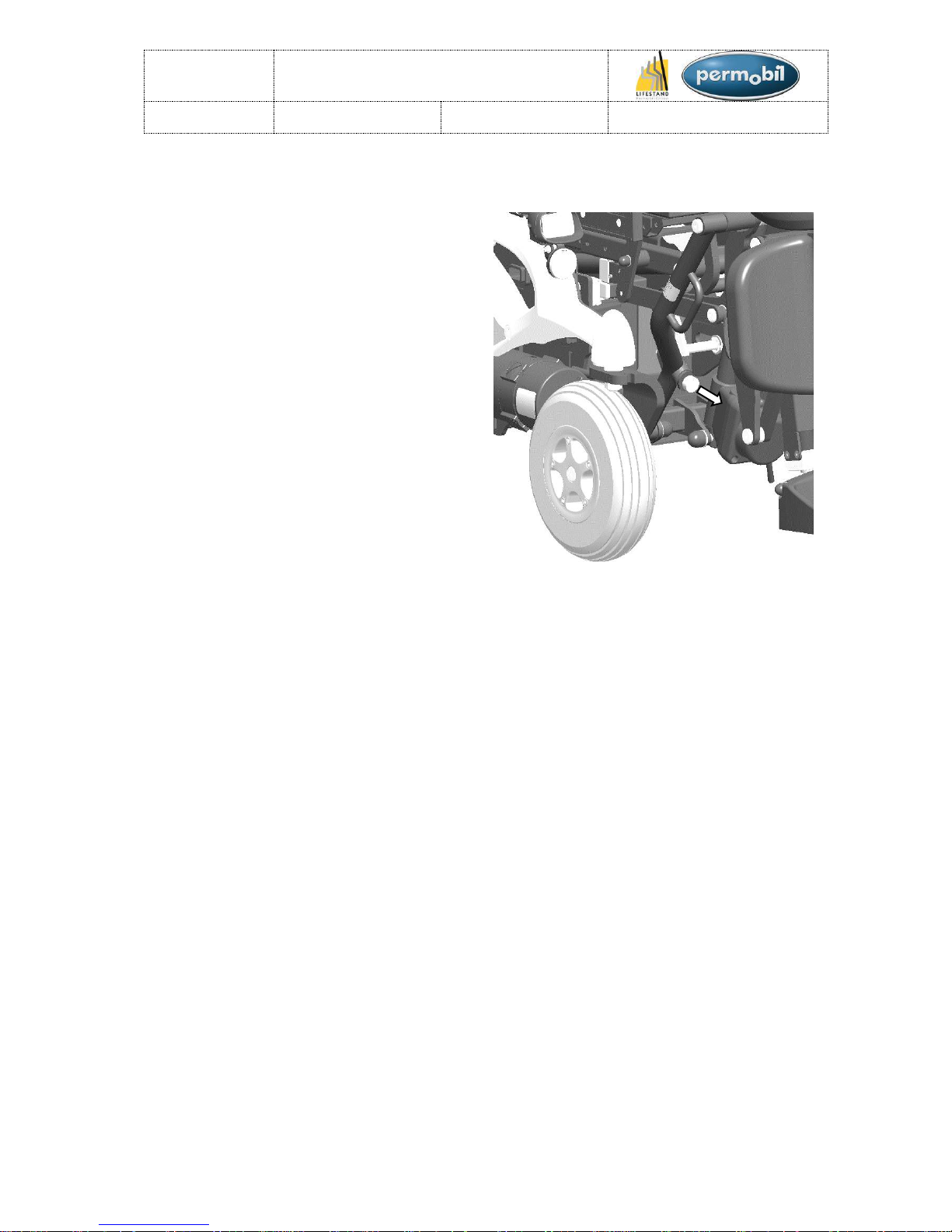
STANDING STOP:
Dismantling:
1. Place the chair in the sitting position.
2. Unscrew the standing stop. (See figure
59)
3. Recover the locknut screwed on the
standing stop and place it on the new
stop.
Assembly:
Assemble in the reverse order.
1. Replace and tighten the standing stop
using the locknut.
REPAIRS:
Figure 59

LSCT
Maintenance manual
Item N° 326617
Revision A
Date 25/06/2015
Page 26 of 93
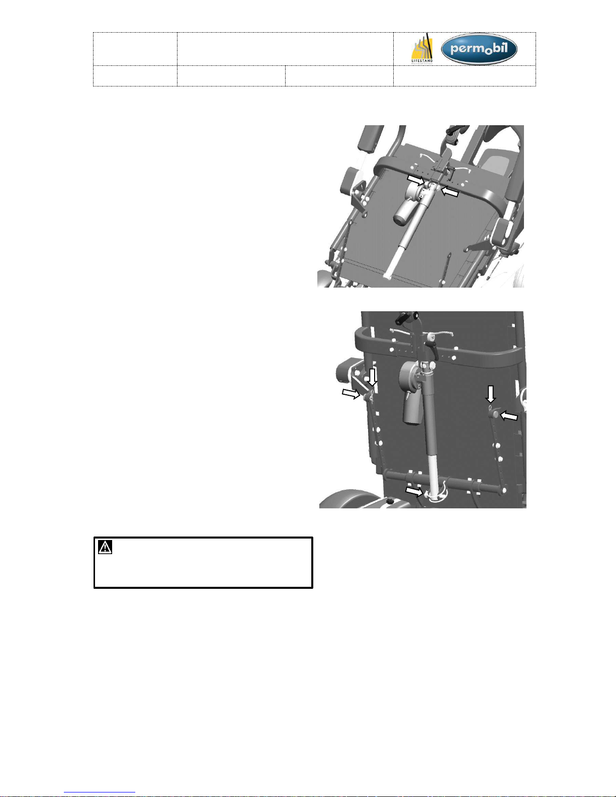
BACKREST ACTUATOR (1/2):
Dismantling:
1. Place the chair in standing position.
2. Remove the back cover (See section
«Back cover»).
3. Cut the clamping collars which hold the
cable from the actuator up to the ISM.
(Note the location of the clamping collars
so that the actuator can be rewired).
4. Place the chair in the sitting position. (Be
careful not to cut the cables which have
been detached when moving from the
standing position to the sitting position).
5. Remove the two pins «a» (See figure 60).
6. Remove the axles which held the pins.
(hold the armrests so that they do not
fall). (See figure 60)
7. Remove the half-moon pin «b». (See
figure 60)
8. Fold down the backrest.
9. Undo the top fastening of the backrest
actuator. (See figure 61)
10. Remove the backrest actuator.
WARNING !
When handling the hinged components
be careful not to pinch your fingers.
REPAIRS:
Figure 60
Figure 61
a
a
b
LSCT
Maintenance manual
Item N° 326617
Revision A
Date 25/06/2015
Page 27 of 93
BACKREST ACTUATOR (2/2):
Assembly:
Assemble in the reverse order.
1. Insert the new backrest actuator.
2. Insert the higher fastening axle of the
backrest actuator and tighten the nut.
(See figure 62)
3. Straighten the backrest.
4. Insert the half-moon pin «b» through the
shaft of the actuator and the lower cross
beam of the backrest. (See figure 63)
5. Insert the axles or the armrest through the
armrest pads and the indexing ties. (See
figure 63)
6. Insert the pins «a». (See figure 63)
7. Place the chair in standing position.
8. Rewire the backrest actuator (See
sections «Electrical circuit diagram» and
«Chair wiring») and replace the clamping
collars.
9. Put back the back cover (See section
«Back cover»).
WARNING !
When handling the hinged components
be careful not to pinch your fingers.
REPAIRS:
Figure 62
Figure 63
b
a
a
LSCT
Maintenance manual
Item N° 326617
Revision A
Date 25/06/2015
Page 28 of 93
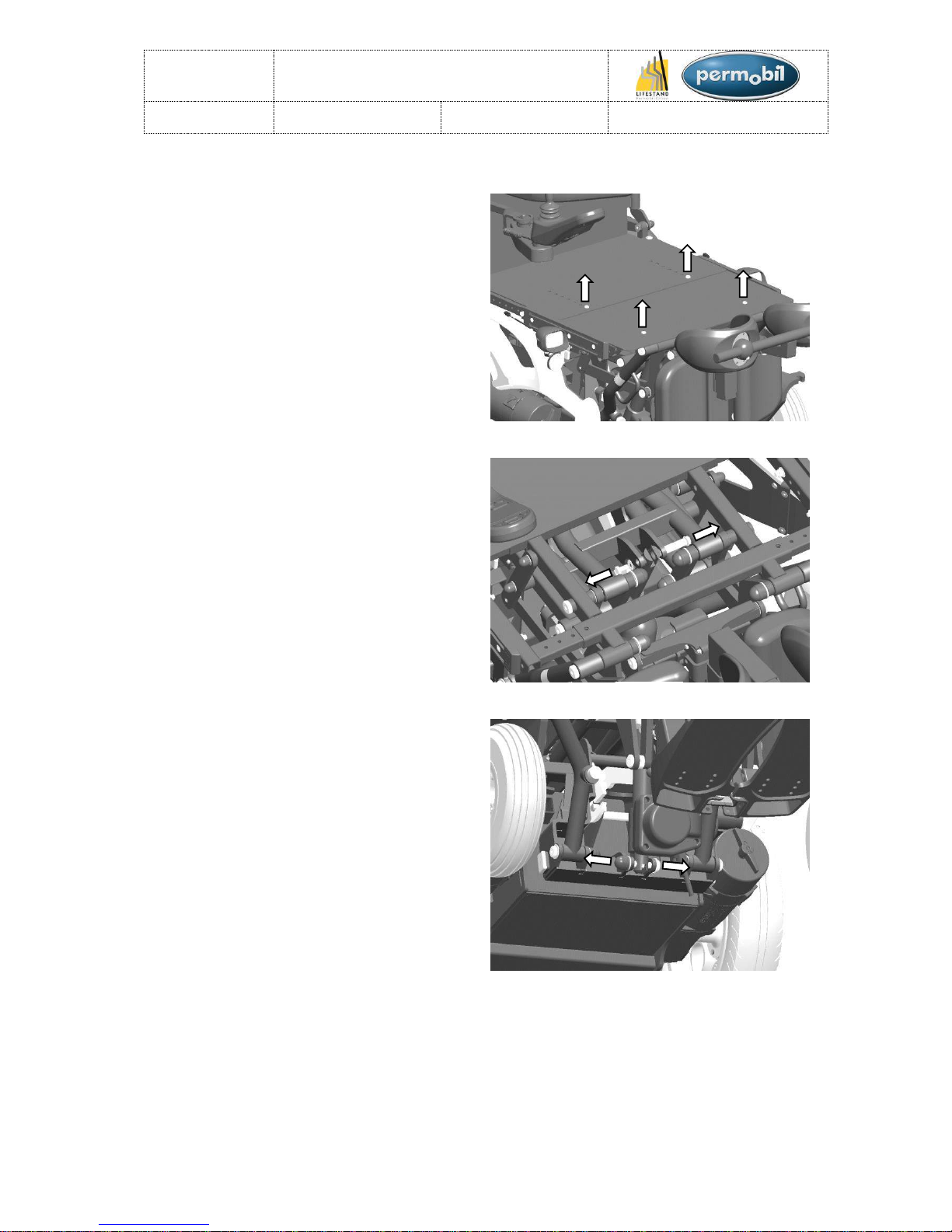
STANDING ACTUATOR (1/2):
Dismantling:
1. Place the chair in standing position.
2. Remove the back cover (See section
«Back cover»).
3. Cut the clamping collars which hold the
cable from the actuator up to the ISM. Do
not disconnect the actuator. (Note the
location of the clamping collars so that the
new actuator can be rewired.).
4. Place the chair in the sitting position.
5. Disconnect the jack plug of the standing
actuator.
6. Remove the seat cushion.
7. Undo the 4 screws holding the front seat
plate. (See figure 64)
8. Remove the front seat plate.
9. Undo the 2 screws above the standing
actuator (Only one of the two screws will
unscrew). (See figure 65)
10. Remove the axle. (Hold the actuator so
that it doesn't fall). (See figure 65)
11. Unscrew the lower actuator fastening.
(See figure 66)
12. Remove the standing actuator.
REPAIRS:
Figure 64
Figure 65
Figure 66
 Loading...