

Lifespan Fitnes ST-13 Owner's Manual
NOTE: This manual may be subject to updates or changes. Up to date manuals are available through our website at www.lifespanfitness.com.au
Product may vary slightly from the item pictured due to model upgrades
Read all instructions carefully before using this product. Retain this owner’s manual for future
reference.
ST-13 OWNER’S MANUAL

2
TABLE OF CONTENTS
1. IMPORTANT SAFETY INSTRUCTIONS 3
2. CARE INSTRUCTIONS 4
3. EXPLODED DIAGRAM 5
4. PARTS LIST 7
5. ASSEMBLY INSTRUCTIONS 12
6. COMPUTER OPERATION 17
7. EXERCISE GUIDE 28
8. WARRANTY 30

3
1. IMPORTANT SAFETY INSTRUCTIONS
WARNING - Read all instructions before using this machine.
It is important your machine receives regular maintenance to prolong its useful life. Failing to
regularly maintain your machine may void your warranty.
Please keep this manual with you at all times
1. It is important to read this entire manual before assembling and using the equipment. Safe and
effective use can only be achieved if the equipment is assembled, maintained and used properly.
Please note: It is your responsibility to ensure that all users of the equipment are informed of all
warnings and precautions.
2. Before starting any exercise program you should consult your doctor to determine if you have any
medical or physical conditions that could put your health and safety at risk, or prevent you from using
the equipment properly. Your doctor’s advice is essential if you are taking medication that affects your
heart rate, blood pressure or cholesterol level.
3. Be aware of your body’s signals. Incorrect or excessive exercise can damage your health. Stop
exercising if you experience any of the following symptoms: pain, tightness in your chest, irregular
heartbeat, and extreme shortness of breath, lightheadedness, dizziness or feelings of nausea. If you do
experience any of these symptoms, you should consult your doctor before continuing with your
exercise program.
4. Keep children and pets away from the equipment. This equipment is designed for adult use only.
5. Use the equipment on a solid, flat level surface with a protective cover for your floor or carpet. To
ensure safety, the equipment should have at least 2 meters of free space around it.
6. Before using the equipment, check that the nuts and bolts are securely tightened. If you hear any
unusual noises coming from the equipment during use and assembly, stop immediately. Do not use the
equipment until the problem has been rectified.
7. Wear suitable clothing while using the equipment. Avoid wearing loose clothing that may get caught in
the equipment or that may restrict or prevent movement.

4
8. This equipment is designed for indoor and family use only
9. Care must be taken when lifting or moving the equipment so as not to injure your back.
10. Always keep this instruction manual and assembly tools at hand for reference.
11. The equipment is not suitable for therapeutic use.
12. The pulse or heart rate sensors are not medical devices. Various factors, including the user’s
movement, may affect the accuracy of heart rate readings. The pulse sensors are intended only as
exercise aids in determining heart rate trends in general.
2. CARE INSTRUCTIONS
a. Lubricate moving joints with grease after periods of usage
b. Be careful not to damage plastic or metal parts of the machine with heavy or sharp objects
c. The machine can be kept clean by wiping it down using dry cloth
d. All nuts and bolts are to be checked and tightened on a regular basis. This includes pedals and other
moving parts. Failure to do so may cause damage to your thread and void your warranty.
5
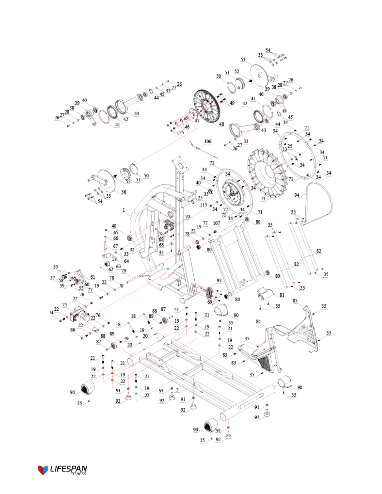
3. EXPLODED DIAGRAM
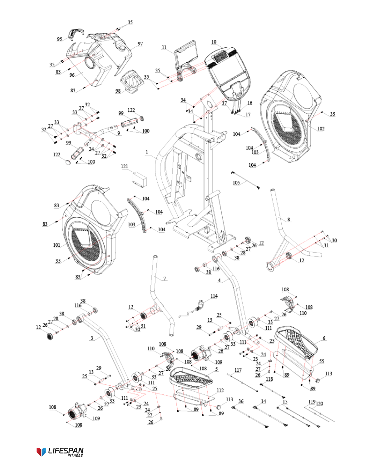
6
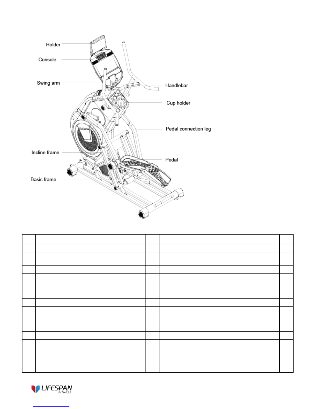
7
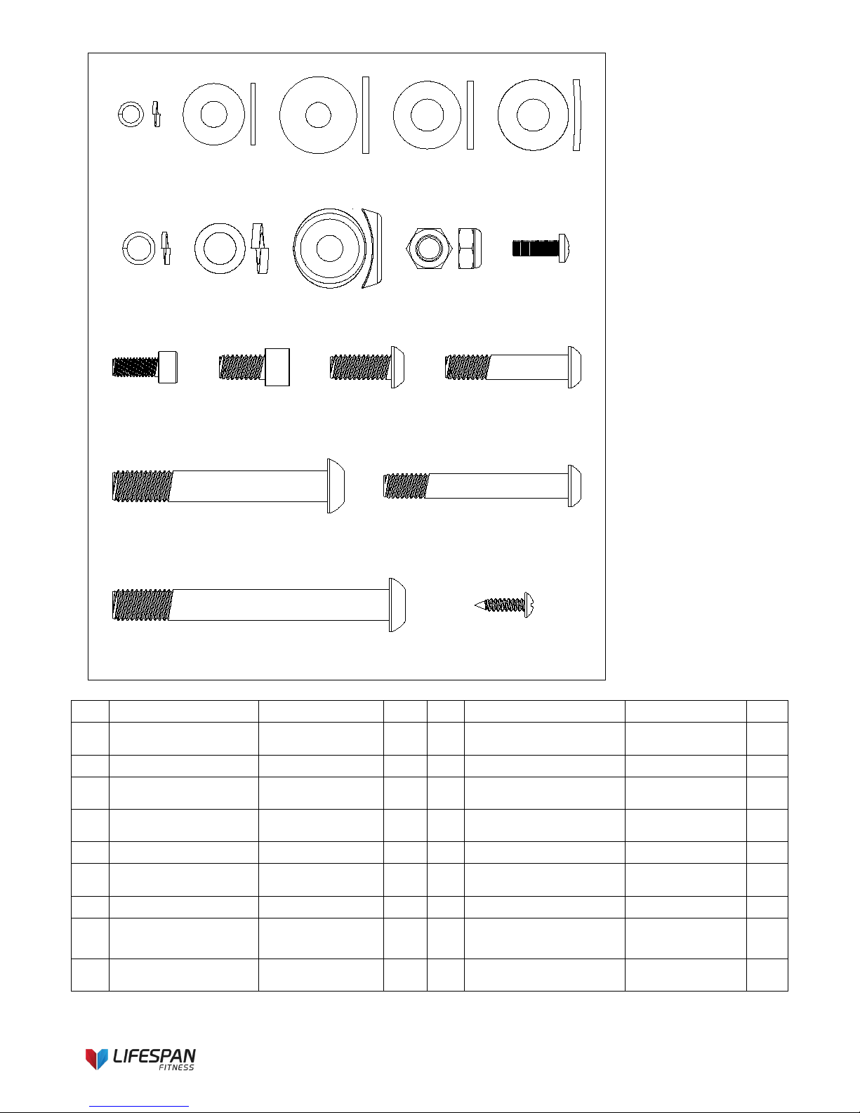
4. PARTS LIST
No Description Specification
Qty
No Description Specification Qty
1
Main frame
1 31
Spring washer
Φ6
6
2 Basic frame 1 32
Allen Pan head full
thread bolt
M8×20 7
3
Left pedal connection leg
1 33
Flat washer
Φ8.5×Φ20×t1.5
22
4 Right pedal connection leg 1 34
Philips C.K.S. full
thread bolt
M5×15 25
5 Left pedal 1 35
Philips C.K.S. selftapping screw
ST4×16
(optional)
30
6
Right pedal
1 36
Communication line B
L-650mm
1
7 Left upper swing arm 1 37
Communication line B
of console
1
8 Right upper swing arm 1 38
Deep groove ball
bearing
6004-ZZ 6
9
Handlebar
1 39
Swing arm
2
10 Console 1 40
Deep groove ball
bearing
6005-ZZ 4
11
I-Pad holder
(Optional)
1
41
Spring washer
Φ120
2
12 Tube cap Φ55 4 42
Deep groove ball
bearing
61819 2

8
13
Roll wheel position
stopper
Φ17×Φ8.5×47 2 43 Eccentric fixer 2
14 Communication line A L-650mm 1 44
Deep groove ball
bearing
6203-ZZ 2
15
Hand pulse
communication line
L-550mm 2 45 Spring washer Φ40 2
16
Hand pulse
communication line of
console
2 46 Spring washer Φ25 2
17
Communication line A of
console
1 47 Crank axle group Φ25×133 1
18
Allen cylinder head full
thread screw
M10×90×20 2 48 Belt pulley Φ308.9×22.2 1
19 Spring washer Φ10 10 49
Allen countersunk head
full thread bolt
M8×20 4
20 Curved washer
Φ10.5×R100×t
2.0
2 50 Spring washer Φ95 2
21
Allen cylinder head half
thread bolt
M10×70×20 6 51 Eccentric wheel Φ103×26 2
22 Flat washer Φ10×Φ22×2.0 12 52
Allen big head full
thread bolt
5/16-18UNC-25 2
23
Allen Pan head half thread
bolt
M8×40×20 4 53 Crank-right 1
24 Curved washer
Φ8.5×R25×t2.
0
8 54
Allen cylinder head full
thread bolt
M8×20 8
25
Hex self-locking nut
M8
12
55
Right Pedal support
1
26
Allen cylinder head full
thread bolt
M8×15 12 56 Crank-left 1
27
Spring washer
Φ8
18
57
Switch
1
28 Flat washer
Φ8.2×Φ25×t2.
0
4 58 Re-set switch 6A 1
29
Allen cylinder head half
thread bolt
M8×60×20 2 59
Allen countersunk head
self-tapping screw
ST3×10 2
30
Allen cylinder head full
thread bolt
M6×15 6 60 Socket 1
No. Description Specification
Qty
No Description Specification Qty
61
Socket fixer
1 94
Motor belt
560PJ6
1
62
Spring washer
Φ10
1
95
Top cover-middle
1
63
Tensioning wheel
Φ43.5×25
1
96
Top cover-left
1
64 Tensioning wheel fixer 1 97 Top cover-right 1
65
Allen nut
M6 1 98
Water cup holder
1
66
Flat washer
Φ6×Φ20×t2.0
1
99
Hand pulse
2
67 Hook 103×Φ26×M6×50 1 100
Philips pan head selftapping screw
ST3×30 4
68 Magnet sensor fixer 1 101 Out cover-left 1
69
Philips self-tapping
screw
ST4×12 8 102 Out cover-right 1
70
Magnet control motor
1 103
Out cover decoration strip
2
71 Flywheel weight stack 6 104
Philips C.K.S. self-tapping
screw
ST4×10 6

9
72
Flywheel
1 105
Mp3 wire
L-400mm
1
73
Flywheel
Φ450×62
1
106
Brake line
1
74
Allen cylinder head
half thread bolt
M10×45×20 1 107 Sliding rail group 1
108
Philips C.K.S. full thread
bolt
M4×10 8
75
Incline motor
1 109
Wheel cover-left
2
76
Hex self-locking nut
M10
2
110
Wheel cover-right
2
77
Allen cylinder head
full thread bolt
M10×15 2 111 Wheels Φ79×37.8 4
78 Powder case Φ32×Φ16×12.7 2 112 Left Pedal Support 1
79
Sliding rail Axle
Φ16×145.5
1
113
Tube cap
Φ32×t1.5
2
80 Tube cap Φ38×17.5 4 114
Power line with computer
tail
1
81 sliding rail tube cover 1 115 sleeve
Φ29×Φ26×4
0
1
82
Sliding rail aluminum
sheet
4 116 sleeve
Φ25×Φ21×2
1
2
83
Philips C.K.S. selftapping screw
ST4×20 8 117 Magnet sensor L-300mm 1
84
Bottom cover-left
1 118
Communication line
L-200mm
1
85
Bottom cover-right
1 119
Power line
L-450mm
1
86
Allen cylinder head
half thread bolt
M10×60×20 1 120 Power line L-450mm 1
87
Allen C.K.S. hollow
bolt
Φ8×33×M6×15 2 121 Controller 1
88 Wheels Φ55×25.8 2 122 Tube cap
Φ39×Φ30×2
7.5
2
89
Allen pan head full
thread bolt
M6×12 10
90
Tube cap
4
91
Hex nut
M10
5
92 Feet pad Φ49×22×M10×40 5
93
Rubber case
110×75×3
1
10
Ø6-6 Ø8.5×Ø20
×t1.5-4
Ø8.2×Ø25
×t2.0-2
Ø10×Ø22
×t2.0-6
Ø8-10 Ø10-8
Ø8.5×R25
×t2.0-8
M8-6
M8×15-4 M8×20-6
Ø10.5×R100
×t2.0-2
M5×15-4
iPad Holder Optional
Accessories ST4×16-4
M8×40×20-4
M6×15-6
M10×70×20-6 M8×60×20-2
M10×90×20-2
No. Description Specification Qty No. Description Specification Qty
18
Allen pan head half
thread screw
M10×90×20 2 27 Spring washer Φ8 10
19 Spring washer Φ10 8 28 Flat washer Φ8.2×Φ25×t2.0 2
20 Curved washer Φ10.5×R100×t2.0 2 29
Allen Pan head half
thread bolt
M8×60×20 2
21
Allen pan head half
thread bolt
M10×70×20 6 30
Allen cylinder head full
thread bolt
M6×15 6
22 Flat washer Φ10×Φ22×2.0 6 31 Spring washer Φ6 6
23
Allen Pan head half
thread bolt
M8×40×20 4 32
Allen Pan head full
thread bolt
M8×20 6
24 Curved washer Φ8.5×R25×t2.0 8 33 Flat washer Φ8.5×Φ20×t1.5 4
25 Hex self-locking nut M8 6 34
Philips C.K.S. full
thread bolt
M5×15 4
26
Allen cylinder head
full thread bolt
M8×15 4 35
Philips C.K.S. selftapping screw
ST4×16(optional) 4
 Loading...