

Page 1

Innovative Fitness Solutions
Page 2

Page 3
#1
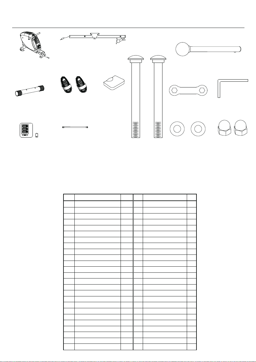
Main frame x 1
Main Contents
#2
Sliding rail x 1
#32
Lock pin x 1
#4
Middle base stand x 1
#7
Pedal x 2
#34
#19
Pedal Axle x 1
Display
Part# Description QTY Part# Description QTY
1
Main Frame
2
Sliding Rail
3
Rear Suppot Stand
4
Middle Base Stand
5
Left Drive Cover
6
Right Drive Cover
7
Pedal
8
Resistance System
9
Seat
10
Seat Support
11
Rollers, Seat
12
Pull handle
13
End Plugs, Handle
14
Foam grips
15
Front Pulley
16
Pulley, Final Lower
17
Pulley, Final Upper
18
Tension Knob
19
Console
20
Sensor wire / Reed switch
21
End Plug for Sliding Rail
22
Front/Rear Feet
23
Transport Wheel
24
Front/Rear Seat Stop
25
Plastic cover for wheel set
#9
Seat
#33
Carriage Bolt x 2
W
rench x 1
#49
Washer x 2
Allen key x 2
#46
Dome Nut x 2
Complete Parts List
1 26
Screw for Rear Stand
1 27
Bolt, Front Pulley
1 28
Bolt, Final Pulleys
1 29
Bolts for attaching seat
1 30
Bolt, Seat rollers/stops
1 31
Sleeve, Seat Roller
2 32
Lock Pin
1 33
Carriage Bolt
1 34
Pedal Axle
1 35
Bolts, Pedals
6 36
Spacer Sleeve, Pedals
1 37
Harness, Reed Switch
2 38
Screw for cover
2 39
Screw for cover
1 40
Screw for cover
1 41
Screw for Tension Knob
1 42
M8 Nylon Nut
1 43
M10 Nylon Nut
1 44
M1/2 Nylon Nut
1 45
M8 Nut
1 46
Dome Nut
4 47
Cap
2 48
M8 washer (big)
4 49
M8 washer (small)
1 50
M10 washer
1
1
2
4
5
3
1
2
1
2
2
1
7
3
1
1
7
2
1
6
2
2
3
2
4
Page 4

Exploded View
14
12
8
28
5
15
2
7
22
38
39
40
34
48
35
50
45
7
17
38
49
42
41
46
32
1
36
4
23
6
13
43
25
16
50
19
20
18
46
49
37
24
49
45
33
22
45
36
45
24
30
24
45
23
9
35
48
7
2
45
24
30
26
47
3
47
44
21
22
42
11
42
31
3
0
29
30
42
10
29
31
42
31
11
42
30
11
Page 5

STEP 1:
ATTACH SEAT TO SLIDING RAIL
a. Remove the 4 Allen Head Screws
b. Place the seat over the seat bracket
29
from the back of the seat.
and tighten all four screws.
9
10
29
STEP 2:
ATTACH MIDDLE BASE TO MAIN FRAME
a. Align the middle base under the
main frame bracket.
b. Insert the 2 carriage bolts
from the bottom.
c. Place a washer over the end
of the carriage bolt and then
tighten the dome nut securely.
46
46
49
49
4
33
Page 6

STEP 3:
ATTACH SEAT RAIL TO MAIN FRAME
a. Line the seat rail directly behind
the main frame and attach the
wire connectors coming from
the seat rail and main frame.
STEP 4:
PEDAL ASSEMBLY
a. Remove the an Allen screw and washer from one end of the pedal axle.
b. Push the end if the pedal axle through the top hole in the frame and
the only hole in the rail, with a spacer on one side. Add the spacer
and the pedal to the other side.
c. Using an Allen Wrench on each end of the axle, tighten the Allen
Screw with the washer that was removed earlier.
37
20
d. Insert locking pin in the lower hole of the main frame while lifting the
sliding rail up slightly near the pedal axle.
7
32
35
48
34
36
36
7
NOTE: Locking Pin will go through the lower hole
in the main frame and under the slide frame.
35
48
Page 7

STEP 5:
INSERT DISPLAY CONSOLE
a. Insert supplied AA battery into the back of display.
b. Connect the cable inside the hole in the front of the
main frame with the connector on the back of the console.
c. Push the display console into the hole
in the in the main frame until secure.
OPERATION
RESISTANCE - To increase the tension turn
the adjustment knob to a higher number and to
reduce the tension, turn the knob to a lower number.
CONSOLE READOUTS - The console will
automatically turn on when the Rower is in use.
If there is no movement for over 4 minutes
the console will automatically turn off.
PAGE: Press the “PAGE” button to scroll
between functions on the console.
RESET: Press the “PAGE” button for 3
STROKES/MIN
COUNTER
DISTANCE
SPEED
TIMER
CALORIES
PAGE
seconds to reset all values to zero.
NOTE: If the display is illegible or only partially appears, remove the battery
for 15 seconds and replace. Battery should be replaced once a year.
Page 8

FOLDING
a. To fold the rower, lift up the sliding rail near the pedal axle to relieve pressure
from the locking pin.
PLEASE READ ALL WARNING LABELS PRIOR TO USE
a
b
c. Lift the seat rail into the upright position and replace locking pin.
b. Remove the locking pin.
 Loading...