

Page 1
R3 & C3 Exercise Bikes
Owners Manual
Version 1.3
Page 2

Page 3

page
Welcome to LifeSpan . . . . . . . . . . . . . . . . . . . . . . . . . . . . 1
Specifications . . . . . . . . . . . . . . . . . . . . . . . . . . . . . . . . . 3
Limited Home Use Warranty . . . . . . . . . . . . . . . . . . . . . . . 4
Important
Safety Precautions . . . . . . . . . . . . . . . . . . . . . . 5
Getting Fit . . . . . . . . . . . . . . . . . . . . . . . . . . . . . . . . . . . . 6
Assembly Instructions . . . . . . . . . . . . . . . . . . . . . . . . . . . 8
Setup and Adjustments. . . . . . . . . . . . . . . . . . . . . . . . . . 18
Console Operations . . . . . . . . . . . . . . . . . . . . . . . . . . . . 20
Congratulations on the purchase of your new LifeSpan exercise bike.
To ensure safe and trouble free operation, we suggest that you read
this Owners Manual and follow its recommendations.
Page 4

We all know that exercise is a key component to achieving the level of Health and Wellness that all
of us desire. Regular activity prevents the development of numerous diseases, helps to reduce
stress, leads to an improved self image, weight loss and increased energy levels.
We also know that in our modern society of fast food, automation and convenience, as a society
we are becoming increasingly sedentary and overweight. At LifeSpan we are working to promote
regular activity. Whether this activity is through physical education in our school systems, sports,
outdoor recreation, or exercising indoors, we believe that increased activity will greatly improve the
health of the average individual in our society.
We designed the LifeSpan product line specifically for people who want to make exercise a part of
their lifestyle. To do this we know that you need a product that is easy to use, comfortable and
built to last.
Easy to Use - means an intuitive easy to read display console, simple adjustments to obtain
proper positioning for each workout, and convenient locations for resistance adjustments, water
bottle holders and storage trays.
Comfortable - includes oversized seats with thick cushioning and built in lumbar support, counter
balanced pedals with a large surface area so they are easy on the feet, and ergonomically correct
positioning that’s easy on the knees, hips and back.
Durability - at the center of any stationary exercise cycle is the drive system - the flywheel, pulleys,
belt, cranks and pedals. The quality and durability of the drive system is only as good as the
weakest component in this system.
The drive system on the C3 and R3 starts with a flywheel that is a full 11” in diameter,
weighs approximately 24 pounds, and places the conductive ring on the outer circumference
of the flywheel. These factors are all critical to obtain a smooth pedal stroke even with high
levels of resistance. The flywheel is complimented by a 7 rib poly V belt, belt tension pulley
that can be adjusted from the outside of the bike, sealed bearings, 3 piece crank set and
counterbalanced pedals. All of these components together ensure a smooth and durable
drive system.
1
Page 5

You can be assured that there is no better value on the market when it comes to Ease of Use,
Comfort and Durability.
Before assembly and operation, please read this Owners Manual. It includes basic information on
starting an exercise program, and safety tips that will assist you in reaching your goals for a
healthy lifestyle.
To keep your stationary cycle in optimal condition, please pay attention to the Operations section of
this manual and remember that some kinds of service should only be performed by a qualified
service technician. If service is required, please contact your authorized LifeSpan Retailer. If a
question or problem arises that cannot be answered by your retailer, contact us:
PCE Health and Fitness
PO Box 981316
Park City, Utah 84098 –1316
Phone: (801) 973-9993
Fax: (801) 973-9923
www.pcefitness.com
Neither PCE Health and Fitness nor its representatives can accept responsibility for any damage
or injury incurred as a result of information presented in the manual except under the terms of
the product warranty.
2
Page 6
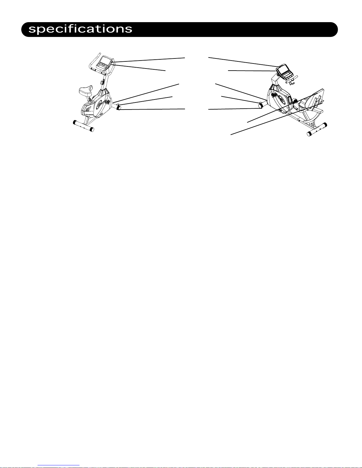
console
metric/english switch
power outlet
transport wheels
levelers
oversized seat with lumbar support
fore and aft adjustment
Console: LCD Readout Display, Program Matrix, Spring Loaded Magazine Holder
and Multi-Position Display adjustment.
Readout:
Time, Distance, Speed, RPMS, Watts, Calories, Program Level and Heart Rate.
Heart Rate: Contact Grip Pulse and Integrated Chest Strap Receiver.
Dimensions: R3: 68 L * 27 W * 45 H
C3: 43 H * 23 W * 57 H
Product Weight: R3: 133 pounds
C3: 101 pounds
Flywheel Size: 11” Diameter/24 lbs. Balanced
Resistance: Circumference ECB Permanent Magnets with Automatic Resistance
Control.
Tension Control: Automatic with 16 levels of resistance
Belt: 7 Rib Poly V
Pedals: Self-Balancing with Easy Adjust Straps.
Power Supply Adapter: Output - 9Volt DC, 7.5W, 1.5A
Frame: Heavy Gauge Steel
Seat: R3: Spine smart design with Integrated Lumbar Support and
Multi-Position Seat Assembly.
C3: Oversized Seat with level adjustment.
Maximum User Weight: 350 LBS
3
Page 7

The LifeSpan R3 and C3 come with the following limited warranty, which applies only to the use of
these cycles in the home, for residential, non-commercial purposes:
• Frame: Lifetime
• Parts: 3 years
• Labor: 1 year
PCE Health and Fitness warrants that the equipment it manufactures is free from defects in mate-
rial and workmanship under normal use and service. The periods above are based on the date of
purchase. During these periods, PCE Health and Fitness will repair or replace any
defective part. Free labor is included for the first year.
If within the time frames specified above, any part of the LifeSpan exercise cycle fails to operate
properly contact your authorized LifeSpan retailer to report the problem. Required labor shall be
supplied by the authorized retailer that sold your product and the product must be located
within that retailer’s service area. If you are unable to reach the dealer that you purchased the
product from, contact PCE Health and Fitness at our web site, www.pcefitness.com or at (801)
973-9993.
PCE Health and Fitness reserves the right to make changes and improvements in our products
without incurring any obligations to similarly alter any product purchased. In order to insure our
product warranty and to ensure the safe and efficient operation of your cycle, only authorized
parts can be used. The warranty is void if any parts other than those provided by PCE Health and
Fitness are used.
Exclusions and Limitations
• This warranty does not apply to any defects caused by negligence, misuse, improper
assembly or maintenance, accident, or an "act of god".
• This warranty does not apply to discoloration of paint or plastics
• PCE Health and Fitness shall not be responsible for incidental or consequential damages.
• This warranty is nontransferable from the original owner.
Registration
You must register your LifeSpan product before a warranty claim can be processed.
To complete your registration card online, go to www.pcefitness.com and fill out
the registration card online or fill out the warranty card provided with your cycle
and mail it today. Registration Cards must be completed and sent to PCE Fitness
within 30 days of purchase to activate the Product Warranty on your LifeSpan equipment.
Product Warranties are not valid unless properly completed and sent to PCE Fitness
within this 30 day period.
4
Page 8

When using equipment, basic precautions should always be followed, including:
• Never drop or insert any object into any opening.
• Never operate your Stationary Cycle if it has been damaged or even partially submersed in water.
• Do not use outdoors, near swimming pools or in areas of high humidity.
• Keep the stationary cycle on a solid, level surface.
• Use this exercise product for its intended use as described in this Owners Manual.
• Do not use attachments that are not recommended by PCE Health and Fitness.
• Wear shoes with rubber or high traction soles.
Do not use shoes with heels, leather soles, cleats or spikes.
• Keep hands and feet away from all moving parts.
Children and Pets
• Keep children off your stationary cycle at all times.
• When in use, young children and pets should be kept at least 10 feet away.
Other Safety Tips
• Always consult a physician before beginning this or any exercise program.
• If you experience chest pains, nausea, dizziness or shortness of breath, stop exercising
immediately and consult your physician before continuing.
Save These Instructions
Note: Read ALL instructions before using your LifeSpan stationary cycle.
5
Page 9

Cardiovascular endurance is the most important component of physical fitness. There are two
types of cardiovascular endurance, these are interval training and steady state training.
Interval training varies the amount of effort required to workout. The LifeSpan C3 and R3
come with several programs that automatically change the pedaling resistance during the
course of the workout. These include the Interval, Weight Loss and Mountain Programs.
Steady state training keeps the resistance the same during the course of the workout. This
includes the Manual Program and the Heart Rate Control programs. Using the Target Heart
Rate program you can pre-select your desired Heart Rate during the Program set-up process.
Regardless of your personal fitness goals and the program that you pursue, warming
up and cooling down before and after you workout will help reduce the risk of injury and
improve the effectiveness of your workout.
Warming up is important to bring your body from its normal level of activity to a state where it
is ready to exercise by increasing the flow of blood to the muscle to raise the muscle
temperature. This will increase the muscle elasticity and protect the joints. The warm up
period also helps to mentally prepare you for your workout.
Warm-ups should be done at a low intensity level and last for at least five minutes.
Cooling down after your workout is required to gradually bring your cardiovascular system
down to its normal level.
Follow your workout with at least 10 minutes of stretching. Focus on the major muscle
groups of the lower extremity. When stretching, stretch the muscle until you feel gentle ten-
sion, hold it and wait for the tension to relax while the muscle elongates, stretch the mus-
cle again until you feel gentle tension.
Do not bounce when you stretch, bouncing is not an effective approach to stretching and can
lead to injury.
The three components of a successful cardiovascular exercise program are:
• Frequency
• Intensity
• Time
6
Page 10

In terms of frequency, you should try and exercise at least three times per week.
200
170
150
120
195
166
146
117
190
162
143
114
185
157
139
111
180
153
135
108
175
149
131
105
170
145
128
102
165
140
124
99
160
136
120
96
155
132
116
93
The intensity of each workout refers to how hard you feel your working and can be measured
by your heart rate. Depending on your fitness goals, exercise between 55% and 90% of your
maximum heart rate. A simple way of estimating your maximum heart rate is by subtracting
your age from 220. As a general rule of thumb, if your fitness objective is to Lose Weight, you
will want to keep your heart rate between 60% and 75% of your maximum heart rate. If your
objective is improved aerobic performance keep your heart rate between 75% and 85% of
your maximum heart rate.
TARGET HEART RATE CHART
100%
85%
75%
60%
200
170
150
120
195
166
146
117
190
162
143
114
185
157
139
111
180
153
135
108
175
149
131
105
170
145
128
102
165
140
124
99
160
136
120
96
155
132
116
93
Increased Performance Range
Aerobic Training Range
Weight Loss Training Range
Low Intensity
20 25 30 35 40 45 50 55 60 65
To achieve benefits from your workout, your workout time should be at least 20 minutes per
session. If you are trying to lose weight focus on longer (more than 30 minutes) less intense
workouts, to improve your aerobic performance focus on shorter more intense workouts.
As a rule of thumb when your exercising, if your having trouble completing a sentence, you are
working too hard. When exercising, you should be able to speak freely without gasping for air.
AGE
7
Page 11

Since your stationary cycle is a heavy piece of equipment, we recommend that you use 2 people
to complete the assembly, as some of the parts need to be held in place while the electrical connectors are pushed together.
Prior to starting the assembly process take all of the parts out of the box, cut zip ties, remove all
plastic bags, and lay them out on the floor to become familiar with the components.
R3 RECUMBENT ASSEMBLY
Step 1: Front Base Assembly
Parts Required
Main Frame
Front Base
Hardware Required
Part # Size Description Quantity
A-1 M10 * 90 Dome Head Allen Screw 2
C-1 M10 Curved Washer 2
C1
A1
1. Locate the hardware bag for Step 1.
2. Place the front base over the frame aligning the holes in the base with the threaded holes
in the frame.
3. Insert the two 6 mm dome head screws (A-1) with bent washers (C-1) into the holes in the
front base and tighten screws.
8
Page 12

Step 2: Rear Base Assembly
Parts Required
Rear Base
Base Frame
Hardware Required
Part # Size Description Quantity
A-1 M10 * 90 Dome Head Allen Screw 2
C-1 M10 Curved Washer 2
C1
A1
1. Locate the hardware bag for Step 2.
2. Place the rear base over the frame aligning the holes in the base with the threaded holes in
the frame.
3. Insert the two 6 mm dome head screws (A-1) with bent washers (C-1) into the holes in the
rear base and tighten screws.
9
Page 13

Step 3: Handlebar Post Assembly
Parts Required
Handlebar Post
Rubber Boot
Hardware Required
Part # Size Description Quantity
A-2 M10 * 120 Dome Head Allen Screw 1
A-3 M10 * 70 Dome Head Allen Screw 2
A-6 M8 * 10 Dome Head Allen Screw 1
C-2 M10 Flat Washer 3
C-5 M10 Spring Washer 3
C2
C5
A2
C2
C5
A3
1. Locate the hardware bag for Step 3
2. Slide the rubber boot over the handlebar post as shown in the diagram.
3. Remove the wire tie holding the harnesses in place and connect the two wiring harnesses.
4. Insert the handlebar post into the frame making sure that the wiring harnesses are not
pinched. It may help to keep some tension up on the harnesses from the top of the
handlebar post.
5. Install Screws:
a. Insert the M10 * 120 mm dome head screw (A2) with Flat Washer (C2) and Spring
Washer (C5) thru the hole in the front of the post.
b. Insert the 2 M10 * 70 mm dome head screws (A3) with Flat Washer (C2) and Spring
Washer (C5) thru the holes in the left side of the post.
A6
6. Once all the screws are in place, securely tighten them using the 6 mm Allen Wrench
included with the hardware kit.
7. Install and tighten the M8 * 10 mm dome head screw (A6) into Console side of the post to
eliminate any play in the handlebar post.
10
Page 14

Step 4. Frame Assembly
Parts Required
Seat Rail
Base Frame
Hardware Required
Part # Size Description Quantity
A-4 M8 * 12 Dome Head Allen Screw 6
A-5 M10 * 15 Dome Head Allen Screw 6
C-2 M10 Flat Washer 6
C-3 M8 Spring Washer 6
C-5 M10 Spring Washer 6
C3
A5
A4
C5
C2
C3
A4
1. Locate the hardware bag for Step 4.
2. Slide the front Main Frame close to the Rear Frame. Connect the wire connectors and slide
the Front and Rear Frames together being careful not to pinch the wires.
3. Carefully tip the bike forward onto its nose so that it balances on the front base and
handlebar post.
4. Install the 6 M10*15 Dome Head Allen Bolts (A5) with M10 Flat Washers (C2) and M10
Spring Washers (C5). Tighten these bolts.
5. Carefully lay the unit back down into the Normal position.
6. Set the Seat Slide Frame on top of the Rear Base Frame.
7. Line the mounting holes up. (4 up front and 2 in the back)
8. Install the 6 M8*12 bolts (A5) with M8 Spring Washers (C3). Once all bolts are started
securely tighten all 6 bolts.
11
Page 15

A-10
M8*16
(A10)
M8*16
Page 16

M4
Page 17

Install Pedals
1. Pay attention to the side the pedals are installed on. The right and left sides are
determined while sitting in a normal riding position. The pedals are marked R for right
and L for left.
2. The Right side pedal is screwed in the normal clockwise tightening direction.
3. The Left side pedal is screwed in the opposite counterclockwise direction.
4. Using the 15 mm supplied wrench, tighten the pedals.
5. Attach the pedal straps.
Water Bottle Holder
1. Line the water bottle holder up with holes just below handlebar and install the 2 Phillips
Head Screws (A8)
2. Securely tighten both screws
14
Page 18

C3 UPRIGHT ASSEMBLY
Step 1: Front Base Assembly
Parts Required
Main Frame
Front Base
Hardware Required
Part # Size Description Quantity
A-1 M10 * 90 Dome Head Allen Screw 2
C-1 M10 Curved Washer 2
1. Locate the hardware bag for Step 1.
2. Place the front base over the frame aligning
the holes in the base with the threaded holes
in the frame.
3. Insert the two 6 mm dome head screws with
bent washers into the holes in the front base
and tighten screws.
Step 2: Rear Base / Seat Assembly
Parts Required
Rear Base
Seat
Hardware Required
Part # Size Description Quantity
A-1 M10 * 90 Dome Head Allen Screw 2
C-1 M10 Curved Washer 2
Rear Base
1. Locate the hardware bag for Step 2.
2. Place the rear base over the frame aligning the
holes in the base with the threaded holes in
the frame.
3. Insert the two 6 mm dome head screws with
bent washers into the holes in the front base
and tighten screws.
Seat
1. Push the seat down all the way onto the seat post spindle.
2. Making sure that the seat points straight forward and is level to the ground, tighten
the two 14 mm nuts on each side of the seat clamp.
15
Page 19

Step 3: Handlebar Post
Parts Required
Handlebar Post
Rubber Boot
Hardware Required
Part # Size Description Quantity
A-2 M10 * 120 Dome Head Allen Screw 1
A-3 M10 * 70 Dome Head Allen Screw 2
A-4 M5 * 15 Phillips Screw 2
A-6 M8 * 10 Dome Head Allen Screw 1
C-2 M10 Flat Washer 3
C-4 M5 Flat Washer 2
C-5 M10 Spring Washer 3
Main Frame
C4
A4
A3
A2
C2
C2
1. Locate the hardware bag for Step 3.
2. Slide the rubber boot over the handlebar post as
shown in the diagram.
3. Remove the wire tie holding the harnesses in place
and connect the two wiring harnesses.
4. Insert the handlebar post into the frame making
sure that the wiring harnesses are not pinched. It
may help to keep some tension up on the harnesses
from the top of the handlebar post.
5. Install Screws:
a. Insert the M10 * 120 mm dome head screw (A2) with Flat Washer (C2) and Spring
Washer (C5) thru the hole in the front of the post.
b. Insert the 2 M10 * 70 mm dome head screws (A3) with Flat Washer (C2) and Spring
Washer (C5) thru the holes in the left side of the post.
6. Once all the screws are in place, securely tighten them using the 6 mm Allen Wrench
included with the hardware kit.
7. Install and tighten the M8 * 10 mm dome head screw (A6) into Console side of the post to
eliminate any play in the handlebar post.
8. Locate the Phillips Head Screws and Washers and install the Water Bottle Holder.
16
Page 20

Page 21

Where to locate your Exercise Bike
Locate your Exercise Bike in a pleasant area that gives you something to look at while your working
out, such as a window or television. Maintaining an exercise program in a poorly lit area is more
difficult than when located in a pleasant and active location.
Allow a distance of 4 feet between the bike and other objects or surfaces on either side.
Stabilizing Your Exercise Bike
After you have placed the bike where you will be using it, check the unit‘s stability by rocking it
back and forth in all directions. Any movement indicates that the bike needs to be leveled. First
determine which foot is not resting on the floor. Loosen the jam on that foot and adjust the foot
down until it touches the floor, then tighten the jam to keep the foot in place. Repeat as necessary
until the bike is completely stable.
On the R3 recumbent, once the unit is stable, you will also need to lower the center foot until it
touches the floor and tighten the hex nut to keep it in place.
Leveling Feet
Power Supply
The R3 and C3 Exercise Bikes comes with an external power supply that plugs into a 110 Volt
power outlet on one end and into the power jack in the front left hand corner of the bike.
Metric/English Mode
Metric/English Switch
Power
Supply
To change between metric (kilometers) and English (miles)
modes there is a switch on the back of the console. When
the switch is in the up position the console is in (kilometer)
mode. When the switches is in the down position the console
is in (mile) mode. To change from one mode to the other
unplug the power cord, change the switch to the desired
mode, and plug the power back in.
18
Page 22

Seat Adjustment
Before working out, make sure that the seat is properly adjusted. Do this by sitting on the seat and
placing the balls of your feet on the pedals. Your knee should be slightly bent when the pedal is at
its furthest point of rotation relative to your body. You should be able to pedal without
locking your knee or shifting in the seat.
Upright Adjustment
Loosen the locking pin on the seat post by turning knob counter clockwise. Pull out on the
knob to allow the seat post to move up and down. Adjust the seat to the proper position and
then tighten the knob by turning it clockwise.
Recumbent
Pull up on the seat adjustment lever located on the right back corner of the seat. Slide the
seat forward and backward as required to give your knee a slight bend when the pedal is
furthest away from your body. Push down on the lever to lock it in place.
Pedal Strap Adjustments
The straps should be tight enough to keep the ball of your foot on the pedals throughout the complete pedal rotation.
Before working out, test each strap and adjust if required.
Each strap comes with a spring loaded clip on the outside of the pedals that keeps the straps in
place. To tighten the strap simply pull down on the loose end of the strap until the strap is properly
tensioned. To loosen the strap, press down on the top of the clip and pull the strap up. Release the
clip and lock the strap in place.
19
Page 23

The R3 and C3 console has several unique features including Multi-position Display Adjustment,
Spring Loaded Magazine Holder and Smart Light Program Setup™. It also includes programs
for Heart Rate Control, Interval training, Weight Loss, Random and Mountain training, plus a
Manual mode.
You can also follow the “Blue” lights on the key pad to see which button needs to be pressed next.
Upon waking up the console, the blue “Up” and “Down” LED lights will be flashing. Once an adjustment is made by using the “Up” and “Down” buttons, the blue light for the “Enter” button will
automatically start to flash showing that this button needs to be pressed next. Upon completion of
the set up process, the “Start” button will begin to flash indicating that you are ready to begin your
workout.
Display Readouts:
WATTS: is an indicator of the amount of work or energy that is being generated.
Speed: the Speed readout shows the Miles Per Hour (MPH) or Kilometers Per Hour (KPH)
that is being pedaled at that time.
RPM: the RPM reading shows how many revolutions per minute the user is pedaling at that
specific point in time.
Distance: shows the distance in miles or kilometers, depending on which is selected.
Time: Either shows the workout time starting from 00:00 or counting down from a time that
was selected in the Program Set-up process.
Heart Rate: Shows the Users Heart Rate at that point in time using the Grip Pulse pads on
the handlebars.
Note: When using the grip pulse, it may take several minutes for the moisture level in your
hands to increase to the point that the sensors begin working properly. Particularly in dry
climates, you may want to use Aloe Vera lotion on your hands.
20
Page 24

Program Profiles
Program 1 - Manual: The Manual program gives you complete control over the resistance level.
If you make a change to the resistance, the new resistance level will stay the same until another
change is made.
The program matrix will show the resistance level history for each segment of the workout.
Program 2 - Interval: The Interval program increases the resistance level for one segment to
raise the Heart Rate and then lowers the resistance to bring your Heart Rate back down. This
is a great program to improve your cardiovascular fitness and with 16 different intensity levels
there is a level that will challenge even the fittest user.
Examples of the Interval program profiles are shown below.
Interval Program Profile - Level 1 Interval Program Profile - Level 3
Interval Program Profile - Level 5
Program 2 - Weight Loss: The Weight Loss program is designed to keep your Heart Rate
between 60% and 75% of its maximum rate. This is the best range for Weight Loss. For best
results, this program should be performed for longer periods of time than the more intense
workouts.
Examples of the Weight Loss Program are shown below:
Weight Loss Program Profile - Level 1 Weight Loss Program Profile - Level 5
21
Page 25

Program 4 - Mountain: The Mountain Program is designed to gradually increase the intensity
of the workout and then gradually bring the intensity back down for a short cool down. Like the
Interval Program this is a good profile for cardiovascular performance.
Examples of the Mountain Program are shown below:
Mountain Program Profile - Level 1 Mountain Program Profile - Level 5
Program 5 - Random: This is a Random program which allows the user to choose from an
infinite number of program profiles. Press the resistance up or down button to select program 5
and press enter. Press the resistance up or down button until you see a program profile you
would like to work out on. Press enter, set the time you would like to work out and press start.
Program 6 - Target Heart Rate: The Heart Rate Control Program lets you select a target heart
rate that you want to maintain throughout the workout. The Target Heart Rate program will
then automatically control the resistance level throughout the workout to maintain your heart
rate at this level. You will need to keep your hands on the EKG Grip Pulse pads on the handlebar.
You can reference the Target Heart Rate chart in the Getting Fit section of this Owners Manual
to help you determine your target heart rate.
Note: When using the grip pulse, it may take several minutes for the moisture level in your
hands to increase to the point that the sensors begin working properly. Particularly in dry
climates, you may want to use Aloe Vera lotion on your hands.
22
Page 26

Program Setup
To Quick Start the Manual program press the Start button.
To select and setup a Program complete the following steps:
Select Program: Use the and buttons to scroll through the list of programs
and press .
Set Level: Use the and buttons to scroll to the desired Level and press .
Set Time: Use the and buttons to scroll to the desired workout time
and press .
Start: Press the button.
The Smart Light Setup feature uses blue button lights to show you which button to push next
during the set-up process. For instance, the arrow buttons will flash at the beginning of each
step showing that these buttons need to be used to select the desired program, level of
resistance, time or weight. After using the arrow buttons, the button will begin to flash
after 3 seconds to let you know that the button now needs to be pressed. At the end
of the program setup process, the button will flash showing that the setup process is
complete and you need to press to begin the workout.
23
Page 27

Page 28

www.pcefitness.com
Park City, Utah 84098-1316
801-973-9993
P.O. Box 981316
 Loading...