

Page 1
LifeSize Room
™
User Guide
Page 2

2 LifeSize Room User Guide
April 2006
Part Number 132-00012-002, Revision 1
Copyright Notice
2006 LifeSize Communications Inc, and its licensors. All rights reserved.
LifeSize Communications has made every effort to ensure that the information contained in this document is accurate and reliable, but
assumes no responsibility for errors or omissions. Information in this document is subject to change without notice. Companies, names, and
data used in examples herein are fictitious unless noted. T his docu ment conta ins copy righted and proprietary information, which is protected
by United States copyright laws and international treaty provisions. No part of the document may be reproduced or transmitted, in any form
or by any means, electronic or mechanical, for any purpose, without t he express written permission from LifeSize Communications.
Trademark Acknowledgments
LifeSize is the trademark of LifeSize Communications, Inc. All other trademarks are the property of their respective owners.
Contacting Customer Support
If you have questions, concerns, or need assistance, cont act your LifeSize Channel Partner.
Providing Customer Feedback
LifeSize Communications welcomes your comments regardin g our products and services. If you have feedback about this or any LifeSize
product, please send it to [email protected]. Contact information for LifeSize Communications is as follows:
Method Address
(512) 347-9300
Fax (512) 347-9301
Page 3
LifeSize Room User Guide 3
Welcome to LifeSize Room
LifeSize Room is the high definition video communica tions system that enables anyone with
dispersed colleagues and operations to collaborate more clearly and effectively.
LifeSize Room meets the following environmental specifications:
Installing LifeSize Room
Your LifeSize Room package includes the following components:
• LifeSize Phone, high definition tabletop speakerphone console with integrated keypad
and display
• LifeSize Camera, high definition pan/tilt/zoom cam er a with w ide -a ng le zoo m len s
• LifeSize Codec, high definition audio an d vid eo com pre ssio n an d decom pr es sio n un it
with stand
• LifeSize Remote, wireless remote control including three AAA batteries
•Cables
• Quick reference card (graphical depiction of proper cabling and equipment setup)
• Documentation CD, including this guide, LifeSize Room Safety and Regulatory Notices,
and the LifeSize End User License Agreement in all supported languages. Also refer to
www.lifesize.com for product document ation and Release Notes.
To install the components of your LifeSize Room system, follow these steps:
1. Remove all components from the product packaging, including cabl es, and place them
in the desired positions in your conference room.
Note: Refer to the LifeSize Room quick reference card included with your system for a
visual depiction of the proper setup.
2. Open the battery compartment on the back side of the remote control, hold the straps
open and insert the three AAA batteries included with your system starting with the outer
batteries first.
Operating Temperature 0°C to 40°C
Operating Humidity 10% to 85%, non-condensing
Storage Temperature -30°C to 55°C
Storage Humidity 10% to 95%, non-condensing
Altitude 0 to 10,000 feet
Page 4
4 LifeSize Room User Guide
3. Insert the codec into its st and by ali gnin g the pin ho les at the base . Se cure the codec in
the stand by tightening the bolt on the bottom of the codec stand. Optional: Insert the
rubber feet on the bottom of the codec stand.
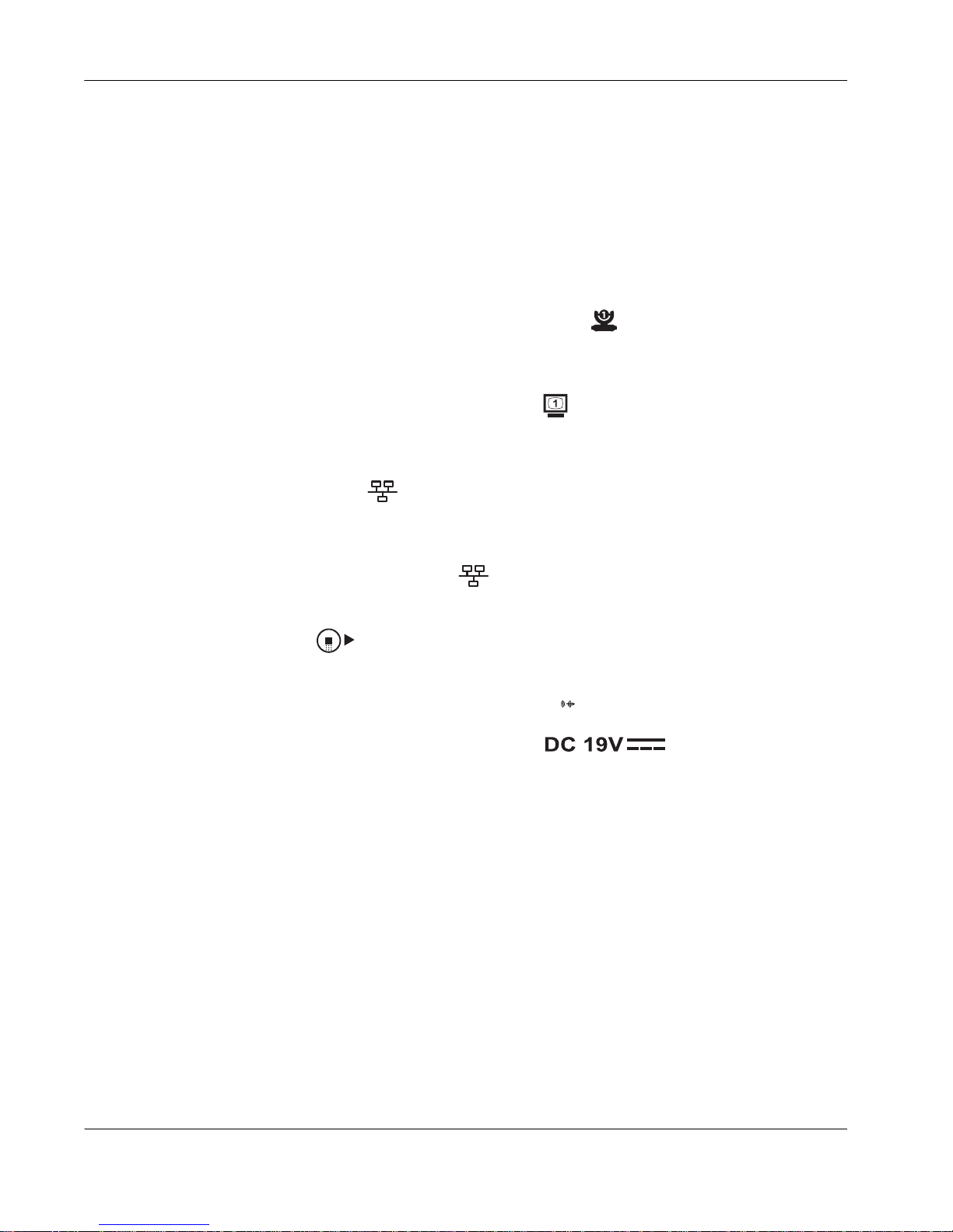
4. Insert the necessary cables into the back panel of the codec, using the plastic guide at
the bottom of the unit to keep all cables secure.
5. Insert the camera cable into the port on the rear side of the camera and plug the
opposite end into port marked with the camera 1 symbol on th e back panel of the
codec.
6. Insert the video display cable into the port on the rear of your display and the opposite
end into the port marked with the display 1 symbol on the back panel of the codec.
Insert the display power cord into a power outlet on the wall.
7. Insert the network cable into the network port on the back panel of the codec; this port is
marked with the LAN symbol . Insert the opposite end of the network cable into a
network port on the wall.
8. Insert the phone cable into the port on the underside of the phone closest to the center;
this port is marked with the LAN symbol . The exterior port is reserved for future
use. Ensure the cables are secured into the guides to avoid damage to them. Insert the
opposite end of the phone cable into the back panel of the codec marked with the
LifeSize Phone symbol .
9. Insert the audio cable into the port on your disp lay and the oppo site end into the line out
port on the back panel of the codec marked with the symbol.
10. Insert the power cord into the power outlet marked on the back panel of
the codec (near the base) and the opposite end into a power outlet on the wall.
11. The camera initializes the first time it is connected to a codec; this process takes about
90 seconds. Do not disturb or disconnect the devices du ring this time as y ou ma y
damage the system.
12. The LifeSize Room system boots, and you are prompted to configure it the first time.
You can change preferences such as the display language, administrator password (for
accessing advanced preferences), locale data, dialing options, and network settings.
Note: For security reasons, LifeSize recommends you change the default
administrator password (1 2 3 4) during the initial configuration.
Once you have completed the initial configuration, you can then place calls, receive calls, or
configure additional preferences.
Page 5

LifeSize Room User Guide 5
Optional Peripherals
You can connect the following optional peripherals to enhance your LifeSize Room system:
You can lock the codec device in your LifeSize Room system with a secure loop to prevent
physical removal of the devices. For assistance, contact your LifeSize Channel Partner or
LifeSize Customer Support.
Peripheral Usage
PCMCIA expansion slots Reserved for future use.
Serial RS-232 Reserved for future use.
Auxiliary In/Out Standard video for use with auxiliary components such as a
DVD player or video recorder.
HD Camera 2 Reserved for future use.
Document Camera In Standard video for use with a third party camera.
XVGA In VGA port for connecting laptops for presentations or to
share PC data.
Audio In (Line In) For use with an external line level audio input, in addition to
the LifeSize Phone. This input is also run through the
Acoustic Echo Canceller (AEC).
LifeSize Networker For use with LifeSize Networker.
Analog phone line in For PSTN connectivity.
Page 6
6 LifeSize Room User Guide
Navigating LifeSize Room
Before using LifeSize Room, familiarize yourself with its components.
Remote Control
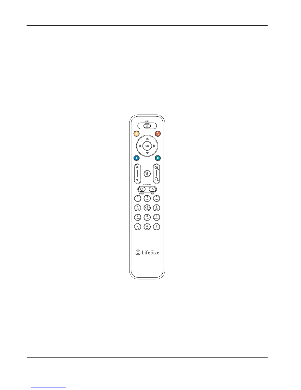
The LifeSize remote control provides wireless control of all system functions. If the system is
idle for a specified time (identified in User Preferences : Appearance : Screen Saver
Timeout), the screen saver is activated. When the system is not in use, it is in standby
mode and the screen is black. An incoming call or pressing any button on the remo te
automatically invokes the system.
The infrared (IR) sensor for the r emote control is located in fron t of the camera. The ef fective
range of the remote control signal is 10 meters (33 feet).
Page 7
LifeSize Room User Guide 7
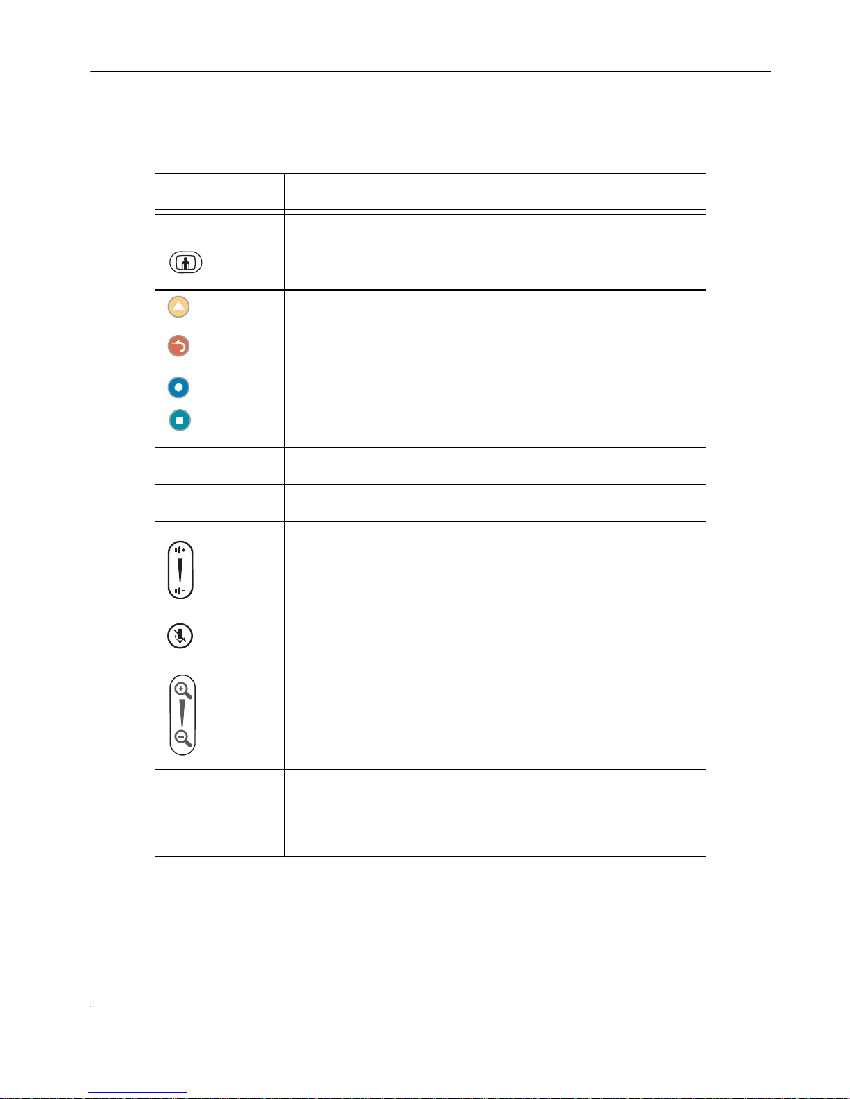
The colored buttons on the remote correspond to functions displayed at the bottom of the
screen. These functions change depending on how you are using the system.
Remote Button Function
Call Returns to the main screen so you can initiate a new call.
These buttons correspond to functions indicated on the screen; their
functionality changes depending on how you are using the system.
OK Behaves as Enter.
Arrows Navigates through items, fields, or areas on the screen.
Increases or decreases the volume.
Mutes the microphones during a call.
Controls the camera zoom. Also behaves as page up and page
down in a multiple page list.
Near and Far Changes the camera control to the near end location or the far end
location. Also displays input selection screens.
Keypad Numeric/alphabetic keypad for character entry.
Page 8
8 LifeSize Room User Guide
User Interface
The user interface includes functions available to all users as well as preferences and
functions restricted to administrators with a password. Use the arrow keys on the remote
control to navigate through the interface.
The main screen has three sections.
• The top of the screen displays system informatio n (such as the system name and phone
number). This information is hidden during a call. Refer to “User Preferences” on
page 21 for details about changing these values.
• The bottom of the screen contains a navigation bar that indicates system status, number
of voice and video calls, time and date (or the duration of a call when a call is in
progress), and network status. Beneath this information, the on-screen buttons display,
indicating the functionality available from that screen. These buttons correspond to
buttons on the LifeSize remote control.
• The center of the screen contains the Redial list and Voice and Video buttons that
enable you to easily place calls.
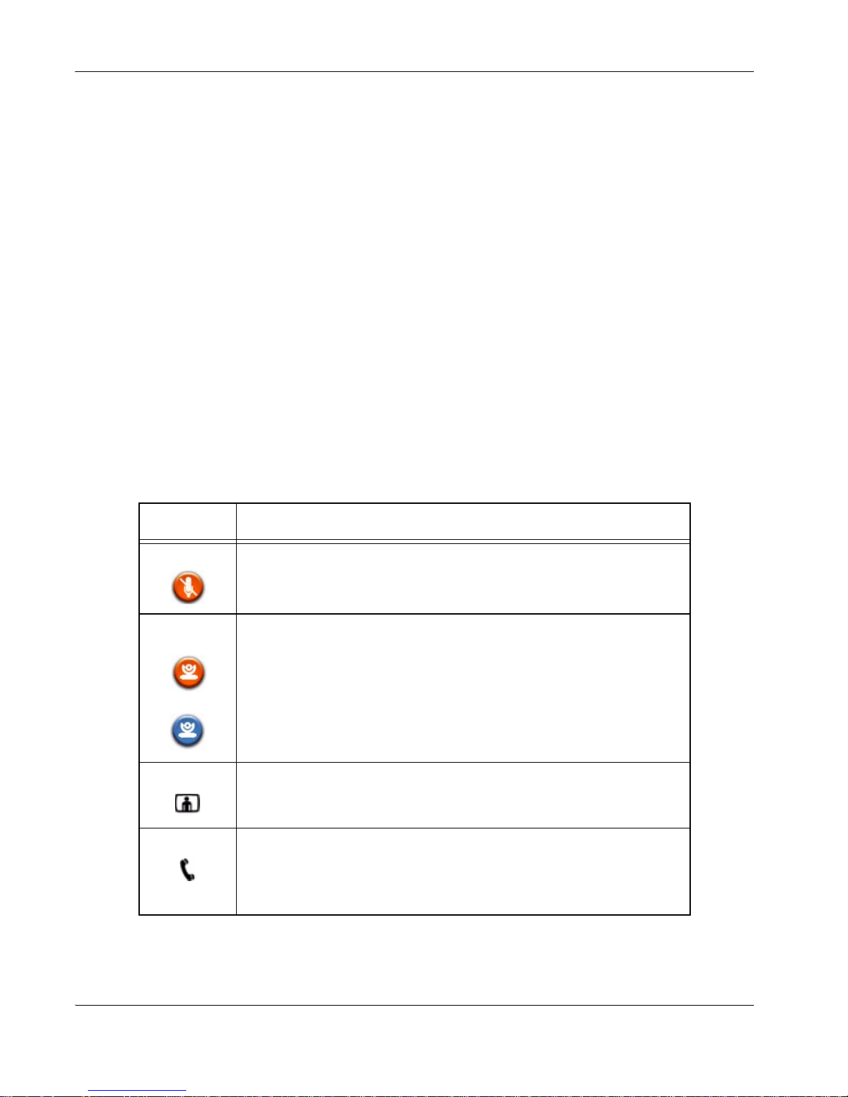
The system displays the following icons to indicate settings and conditions:
Icon Condition
Mute This icon displays near the video of the muted end of the call to indicate
that the microphones are muted.
Near
Camera
Far Camera
Indicates the camera currently being controlled.
An orange icon represents the near end camera.
A blue icon represents the far end camera.
Video The number of video calls in progress.
Voice The number of voice calls in progress.
Page 9
LifeSize Room User Guide 9
Placing and Answering Calls
The LifeSize Phone high definition audio con f er e ncing spea ke rpho ne is fu lly i ntegrated with
LifeSize Room and doubles as the microphone for a vid eo system. You can make both
video and voice calls using LifeSize Room.
Answering, Ignoring, or Rejecting a Call
Incoming calls connect automatically if Auto Answer is set to Enabled. Refer to
“Automatically Answering Calls” on page 12 for details. Otherwise, choose one of the
following options when an incoming call arrives:
•Select Answer and press OK to accept the call.
•Select Ignore and press OK to reject the call.
If you receive an incoming call while you are in another call and Auto Answer Multiway
Call is set to Disabled, you can choose Do Not Disturb which ignores the call and prevents
any other calls from interrupting for th e du ra tio n of the call.
Choosing Dialing Options
LifeSize Room provides simultaneous video, VoIP, or PSTN connectivity.
You can choose voice and video dialing options during the initial configuration or at any
other time by accessing the Administrator Preferences. See your system administrator to
select the protocol to use when dialing voice or video calls.
When placing a call off hook (using the Voice button on the phone) and voice dialing is set
to touch tone or pulse, you can dial only phone numbers using PSTN connectivity. When
voice dialing is set to VoIP, you can dial IP addresses as well as phone numbers.
When dialing on hook (using the remote control or using the Video button on the phone),
you can dial either phone numbers or IP addresses. This enables systems inside a
corporate network without access to a gateway to call other LifeSize Phones in the network
using system IP addresses.
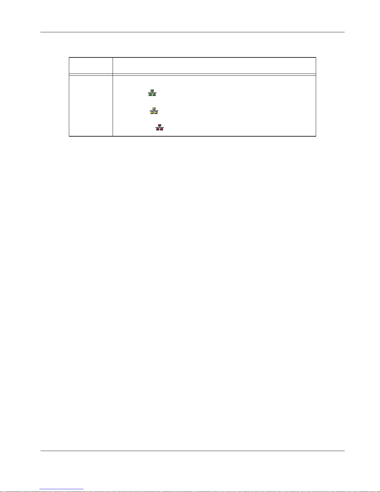
Network
Status
Identifies the network status, as follows:
connected
in progress
disconnected
Icon Condition
Page 10

10 LifeSize Room User Guide
Placing a Video Call
You can place a video call in any of the following ways:
• Select a number from the Redial list.
•Press the Video button on the LifeSize Phone connected to your LifeSize Room system
and enter a number.
• Enter a new number from the display.
To enter a new video number from the LifeSize Room display, follow these steps:
1. Using the remote control, select the Video button on your LifeSize Room display and
press OK.
2. Enter the number you wish to call. The last manually entered number appears by
default. Press OK to exit the field.
- The button changes text entry mode (indicated at the bottom of the screen).
- The button behaves as backspace.
- The button displays the keyboard from which you can enter alphabetical
characters. Use the arrow keys to navigate to the character you wish to enter and
press OK.
3. Optional: Navigate to the bandwidth dropdown list and cho ose a value fo r the maximum
bandwidth for the call. (Press OK to enable the dropdown list, use the arrow keys to
select a value, and press OK again to save your selection.)
4. Select Place Call and press OK to dial the number.
The call status and caller ID information display and the time and date change to a call
timer indicating the length of the call.
5. You can add a second caller while the first call is connecting. Refer to “Includi ng Multiple
Sites in Calls” on page 12.
To view the display with Picture in Picture (PIP) when using more than one video input, refer
to “Selecting and Adjusting a Camera” on page 15.
Page 11

LifeSize Room User Guide 11
Placing a Voice Call
You can place a voice call in any of the following ways:
• Select a voice number from the Redial list.
• Press the Voice button on your LifeSize Phone and enter a number.
• Enter a new number from the display.
To enter a new voice number from the LifeSize Room display, follow these steps:
1. Select the Voice button and press OK.
2. Enter the number you wish to call. The last manually entered number appears in this
field by default.
3. Press OK to place the call.
The call status and caller ID information display and the time and date change to a call
timer indicating the length of the call.
Ending a Call
You can end a call in any of the following ways:
• From the Redial list. Refer to “Using the Redial List” on page 13 for more information.
• From the LifeSize Phone by pressing the Voice button .
• From the Call Manager dialog.
To hang up a call from the Call Manager dialog, follow these steps:
1. Press OK when you are in a call.
The Call Manager dialog displays.
2. Choose one of the following:
- To hang up a single call, press OK again to end the call.
- To hang up any individual caller in a multiway call, use the arrow keys on the remote
to navigate to the caller with which you wish to end the connection, and press OK.
- To hang up all callers in a multiway call, press the left arrow key on the remote to
select the Hang Up All button. Press OK to terminate the connection with all callers.
- To hang up only voice callers or only video callers, use the arrow keys on the
remote to navigate to and select the Hang Up Voice or Hang Up Video buttons.
Press OK to termin ate the connection with all voice or video callers. This optio n only
appears when both voice and video calls are in progress.
Page 12

12 LifeSize Room User Guide
Including Multiple Sites in Calls
You can add participants to an existing call at any time. LifeSize Room su pports 4 -way video
calls (an original caller and three other sites) for easy addition of participants during a call.
You can add a second caller while the first call is connecting; you do not need to wait for the
first call to connect.
To add callers to an existing call, follow these steps:
1. When you are in a call, press the button to return to the main screen to add a new
caller.
An orange LED indicator displays in the Redial list to the left of the voice or video
numbers currently in a call.
2. Select a number to call from the Redial list and press OK, or select the Voice or Video
buttons and enter a new number to ca ll.
Note: You can also press the Add key on the speakerphone keypad and enter the
new number to call. If a call using PSTN connectivity is connected, you must use the
remote control to add calls.
3. Refer to “Ending a Call” on page 11 for options of ending individual calls or all calls.
Automatically Answering Calls
You can set the Auto Answer user preference to connect an incoming call automatically.
You can also specify to mute an auto answered call.
Refer to “User Preferences” on page 21 for more informatio n.
Auto Answer If set to Enabled, the system automatically answers the first
incoming call. If set to Disabled (the default), you must
manually answer incoming calls.
Auto Answer Mute If this preference and the Auto Answer preference are set
to Enabled (the default), the system is muted when the call
connects.
Auto Answer Multiway
Call
If set to Enabled (the default), the system automatically
answers incoming calls after the first call has connected.
The system beeps to indicate a new call has connected.
Page 13

LifeSize Room User Guide 13
Using the Redial List
You can store up to 13 numbers (9 is the default) in the Redial list; refer to “User
Preferences” on page 21 for details about changing this setting. Scroll bars indicate when
there are more than 5 entries in the list. The last call always appears at the top of the list.
When you have reached the maximum number of entries, the entry that has been in the list
the longest is removed. You can lock entries to prevent an entry from being removed from
the list. The lock symbol appears to the right of an entry in the Redial list that has been
locked.
To lock an entry in the Redial list, follow these steps:
1. Using the arrow keys, select the entry you wish to lock.
2. Press the button to lock the number in the Redial list.
A lock symbol displays to the right of the entry.
3. To unlock the entry, press the button again.
The asterisk key removes numbers from the Redial list, including locked numbers.
The Redial list also serves as a simple call manager from which you can hang up calls in
progress (by selecting the call you wish to end and pressing OK), initiate new calls, or add
callers to a existing call. For details about these actions, refer to “Placing and Answering
Calls” on page 9.
Managing Audio
The LifeSize Phone includes support for:
• 16 microphones in a circular microphone array
• Beam forming for high directivity
• Audio response from 100 Hz up to 16 kHz
• Spatial and CD quality audio, full duplex for natural conversations
• Echo cancellation for echo-free calls, automatic gain control, and noise reduction
• Support for the following audio standards: AAC-L C, G.722, G.722.1, G.729, G.711
When the LifeSize Phone is connected to a LifeSize Room system, you are unable to
configure it as a standalone speakerp hone. Configure your system using the LifeSize Room
interface.
Page 14
14 LifeSize Room User Guide
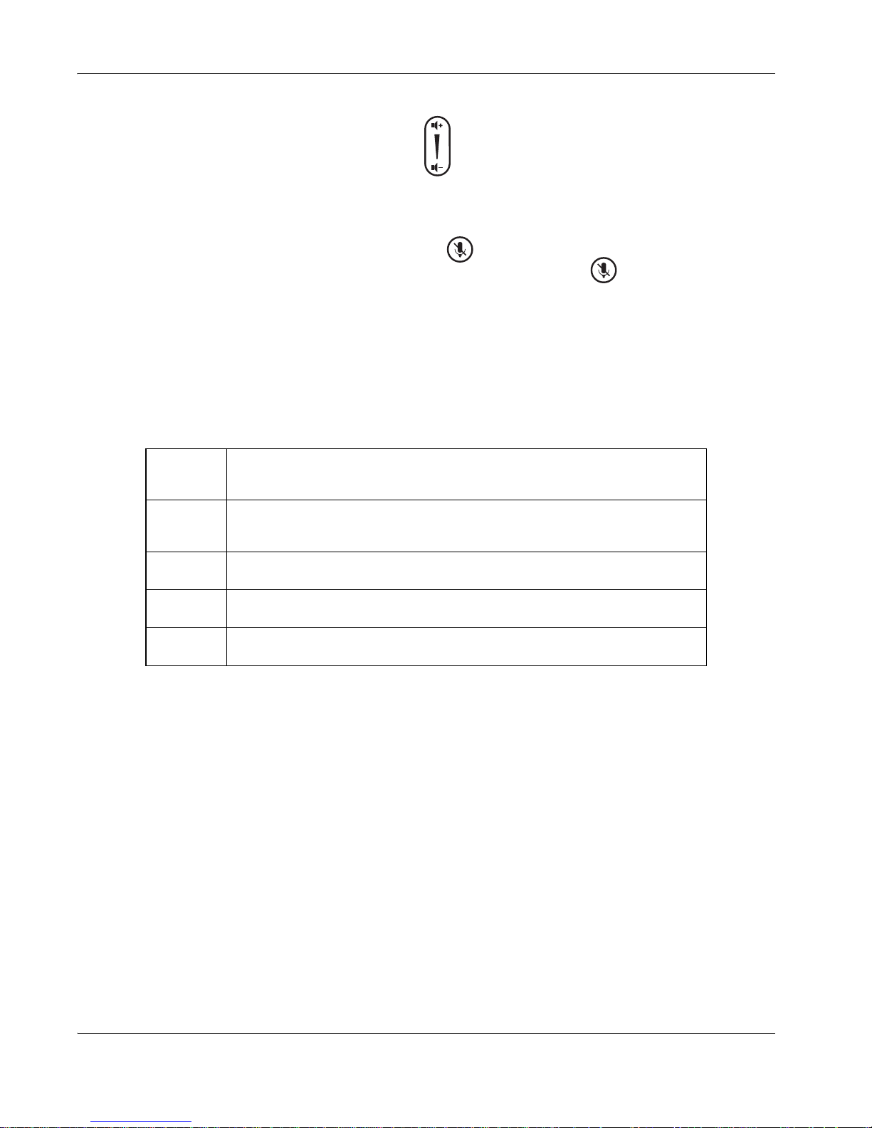
Adjusting Volume
You can adjust the volume of a call using the button on the remote control or on the
phone.
Muting Microphones
To mute the microphone during a call, press the button on the remote control or on the
phone. An onscreen indicator shows the mute status. Pressing the button again reactivates the microphone.
When the far end enables mute (turns off their microphone), an indicator displays on the fa r
end input window.
Managing Audio Quality
The system automatically selects the best audio algorithm based on the call rate and the
capabilities of the remote system. The following standard codecs are currently supported:
Refer to your administrator (or to “Configuring Audio Behaviors” on page 27) to specify the
order of audio algorithms so that you can reduce low quality audio, or if you have
interoperability issues when calling other systems.
Managing Video
The LifeSize high definition pan/tilt/zoom camera includes:
• Wide angle zoom lens with a 70 degree field of view
• Resolution of 1280 x 720, 30 frames per second
AAC-LC CD-quality audio, MPEG-4 Advanced Audio Coding Low Complexity (AAC-
LC with variable bit rate)
G.711 Normal quality audio (telephone quality 3.1kHz at 64kb/s), both A-Law and
µ-Law
G.722.1 Compressed high quality audio (7 kHz at 24kbps, 32kb/s)
G.722 High quality audio (7 kHz at 48kb/s, 56kb/s or 64kb/s)
G.729 Compressed normal quality audio (telephone quality at 8kb/s)
Page 15
LifeSize Room User Guide 15
Selecting and Adjusting a Camera
The LifeSize remote control operates pan, tilt, and zoom functions for adjusting the camera:
• Left and right arrows to pan
• Up and down arrows to tilt
• Zoom in and zoom out keys to zoom
A camera icon displays in the input window for the camera you are controlling when using
these functions. For example, an icon inside the picture-in-picture window indicates control
of the primary (near) input. To adjust the camera before a call, press Near and then adjust
the camera.
Far End Camera Control
You can control the far end camera if it is enabled properly. Far end camera control works
only when you are in a call and the far end side supports Annex Q. You control a far end
camera in the same manner as you would control a near end camera. To select which
camera to control during a call, press the Far button twice and then press the key to
select the camera you wish to control.
To prevent far end users from controlling your near end camera, see your administrator (or
refer to “Configuring Video Behaviors” on page 28).
Managing Video Call Quality
LifeSize Room systems are based on the latest H.264 standard and provide support for
H.263 for interoperability with all standards-based video communications systems.
The system automatically selects the best video algorithm based on the video source and
capabilities of the remote system.
LifeSize Codec
The LifeSize codec compresses outgoing video, audio, and data, transmits this information
to the far end, and decompresses incoming information. You should not need to interact with
the codec once it has been properly set up in your environment unless you are experien cing
problems. See your administrator for infor mation about resetting or reb ooting the cod ec and
its proper setup.
H.264 Improved video compression and decompression.
H.263 Normal video compression and decompression.
Page 16

16 LifeSize Room User Guide
Managing the Display
LifeSize Room connects to most displays, including:
• Plasma flat panel displays
• CRT monitors (720p displays)
• Large screen rear projection TV displays (720p displays)
• Front projection displays
• Rear projector A/V room configurations
If you connect your system to an unsupported display, an error message appears. Ensure
your monitor or projector meets display resolution requirements. Refer to the LifeSize Room
Release Notes for specific resolutions supported.
Your display shows the far-end and near-end video conferencing sites in addition to the
menus and video from conne cted video sources. Refe r to “User Preference s” on page 21 for
details about customizing display settings.
Selecting Input
To select a new input, follow these steps:
1. Press the Near button on the remote control (or navigate to the PIP window and press
OK to enable full screen for the primary input.)
2. Press the Near button again or press the button to display the Primary Input
selection dialog containing small representations of the available input sources.
The default primary input is the High Definition Camera.
3. Accept the default by pressing OK, or change the default valu e b y se lecting the de sir ed
input and pressing OK.
4. Press the button to proceed to the Secondary Inp u t selection dialog containing
small representations of the available input source.
The default secondary input is the VGA input, named PC.
5. Accept the default by pressing OK, or change the default valu e b y se lecting the de sir ed
input and pressing OK.
6. Press the button to return to the main screen and place a call.
To define custom input names, see your adminis trator to change the default values. Refer to
“Configuring Video Behaviors” on page 28 for more information.
Page 17
LifeSize Room User Guide 17
You can also define background images for each display and choose the screen saver style.
Refer to “User Preferences” on page 21 for more information about accessing these
settings.
Hiding User Interface Elements
To hide the user interface elements during a call, press the button on the remote
control. This removes the system information and navigation bar from the screen for the
duration of the call.
You can adjust the preference in User Preferences : Appearance : Fade Out Timer to
identify the duration the user interface waits before it fade s during a call. This duration resets
after any interaction with the system. The default is 10 seconds.
Managing PIP
Picture In Picture (PIP) is a smaller window place d in one of the cor ners of the main screen.
This second image is placed on top of the main image and always displays the primary
(near) input by default.
Refer to “User Preferences” on page 21 for details about this prefer ence. Refer to “Selecting
Input” on page 16 for instructions on changing the primary input.
Dual Display Configurations
LifeSize recommends using a dual display configuration for presentations. To set up your
LifeSize Room system using two displays, connect your secondary display as you did for
your primary display as described in “Installing LifeSize Room” on page 3. Insert the video
display cable into the port on the rear of your display and the opposite end into the displa y 2
port on the back panel of the codec. Attach the display power cord to a power outlet.
Set the Secondary Display Layout in User Preferences : Appearance to reflect the
physical arrangement of your system. Choose Adjacent if your displays are positioned next
to each other; choose Apart if your displays are positioned away from each other. Apart is
only applicable for use with presentations.
Setting Description
On Picture In Picture always displays, even if you hide the user interface elements.
Off Picture In Picture never displays.
Auto Picture In Picture automatically appears when it is suitable.
When you hide the user interface elements, PIP is also hidden. This is the default setting.
Page 18
18 LifeSize Room User Guide
You must then set the secondary input as described in step 1 of the following procedure and
in “Selecting Input” on page 16.
Presentations
LifeSize Room includes H.239 support for sharing presentations or data on a PC while
simultaneously displaying the main video. Th is enab les you to view a live presen te r an d the
content at the same time. LifeSize recommends using a dual display configuration as
described in “Dual Display Configurations” on page 17.
To initiate a call in presentation mode, follow these steps:
1. If you wish to change the primary and secondary input s you can do so eithe r prior to th e
call or during the call. To change inputs during a call, proceed to step 2. To designate
inputs prior to the call, follow these steps:
a. Press the Near button, or navigate to the picture -in-picture windo w using the arrows
and press OK.
b. Press the Near button again or press the button to display the Primary Input
selection dialog.
The default primary input is the High Definition Camera.
c. Accept the default by pressing OK, or change the default value by selecting the
desired input and pressing OK.
d. Press the button to proceed to the Secondary Input selection dialog.
The default secondary input is the VGA input, named PC. The secondary input is
used for presentations.
e. Accept the default by pressing OK, or change the default value by selecting the
desired input and pressing OK.
You are now ready to make a call.
f. Press the button to return to the main screen.
2. Choose a number from the Redial list, or select the or buttons and enter a
number to call. (The last manually entered number appears in this field by default.)
Refer to “Placing a Video Call” on page 10 and “Placing a Voice Call” on page 11.
3. If you did not change the primary and secondary input s in step 1 and do not want to use
the default values, change them now . Ensure you are controlling the near camera, press
Near to select the Primary Input, and press Near again to select the Secondary Input.
Page 19
LifeSize Room User Guide 19
Press Near a third time to remove the input selection from the screen. To select a far
side camera to control during a call, press the Far button twice and then press the
key to select the camera you wish to control.
4. Press the button to start the presentation.
Note: If one of the systems in a call does not support H.239, no second media channel
is established, and the button does not display. In this case, you must manually
invoke the presentation by selecting PC (or the desired input) as the primary input in
order to show the presentation.
5. Press the
button again to stop the presentation.
Note: You can change inputs at any time during a call. The far end can also start a
presentation, which halts the current presentation at the near end.
Using the Directory
The directory is H.350 compliant and provides a list of names and numbers from which you
can make calls. Yo u can store up to 1000 entries in both an alphabetical and hierarchical
format.
To access the directory, press the button from the main screen. The directory is
comprised of local and corporate entries. The local directory is stored on the system and
includes modifiable entries. The corporate directory is read only and is automatically
populated.
If you leave the directory and return to it at a later time, you return to the same place at
which you left it. To move up one level, press the button.
To add an entry to the local directory follow these steps:
1. Using the arrow keys, navigate to the Add New Entry button and press OK.
The New Directory Entry screen displays.
2. Use the arrow keys to navigate through the screen and enter new data, including a
System Name and IP address or ISDN numbers.
a. Press OK to select a field and enter a value.
Note: If necessary, press the button to change the text entry mode for text fields.
b. After entering a value, press OK to exit an individual field.
Page 20

20 LifeSize Room User Guide
3. When you have completed the fields, use the arrow keys to navigate to the Add Entry
button and press OK.
Note: You can define hierarchies, for example by location or department, in which to
group entries. You must identify the full path (separated by commas) of a predefined
hierarchy to which to add an entry prior to completing th e New Directory Entry screen.
If you leave the Hierarchy field empty, the new entry is inserted at the top of the
hierarchy (if defined) or is grouped alphabetically.
To remove an entry from the local directory, follow these steps:
1. Using the arrow keys, select the entry you wish to delete.
2. Press the button.
3. Select Yes from the confirmation dialog and press OK to delete the entry.
To edit an entry in the local directory, follow these steps:
1. Using the arrow keys, select the entry you wish to edit.
2. Press the button.
The Edit Directory Entry dialog displays with the details of the entry.
3. Use the arrow keys to navigate through the dialog and modify values.
a. Press OK to select a field you wish to modify.
Note: If necessary, press the button to change the text entry mode for text fields.
b. After completing your changes, press OK to exit the field.
4. Using the arrow keys, navigate to the Save Changes button and press OK.
Page 21

LifeSize Room User Guide 21
User Preferences
To access user preferences accessible to all users, follow these steps:
1. Press the button from the main screen to access the System menu.
2. Select the User Preferences button.
The following settings are available from the User Preferences menu.
Preference Default Description
Appearance
Language English Select the language for the text that displays on the screen.
System Name LifeSize Enter a descriptive name for the device.
Phone Number [number] Enter the phone number of the device.
Secondary Display
Layout
None Select the layout of the secondary display to correspond to the physical
arrangement of your conference room.
Fade Out Timer 10
seconds
Select the duration the user interface waits before it fades during a call.
This duration resets after any interaction with the system.
Caller ID Timeout 1 minute Select the duration the caller ID remains on the screen during a call.
This duration resets after any interaction with the system.
Picture In Picture Auto Select 'On' to display PIP continuously, 'Off' to never display PIP, or
'Auto' to display PIP only when the user interface is visible.
LCD Contrast 6 Select the contrast of the LCD for the LifeSize Phone.
Display 1 Background Default Select a background image to present on Display 1.
Display 2 Background Default Select a background image to present on Display 2.
Screen Saver LifeSize Select 'LifeSize' to display the LifeSize logo or 'Window' to display a
portion of the background as the screen saver. Select 'None' to display
the main screen.
Screen Saver Timeout 10
minutes
Select the duration of idle time to wait before displaying the screen
saver.
Sleep Timeout 10
minutes
Select the duration of idle time to wait before the system reverts to
standby mode. This time is added to the Screen Saver Timeout.
Calls
Page 22

22 LifeSize Room User Guide
Maximum Redial
Entries
9 Select the maximum number of entries to store in the redial list.
Auto Answer Disabled Choose 'Enabled' to automatically answer the first incoming call.
Auto Answer Mute Enabled If Auto Answer is set to 'Enabled', choose 'Enabled' to mute the system
when the call connects.
Auto Answer Multiway
Call
Enabled Choose 'Enabled' to automatically answer incoming calls after the first
call has connected.
Audio
Treble 0 dB Select the higher frequencies in the sound range for the audio line
output.
Bass 0 dB Select the lower frequencies in the sound range for the audio line
output.
Ring Tone Volume 5 Select the volume level of the ring and busy tones.
DTMF Tone Volume 5 Select the volume level of the DTMF and key click tones.
Preference Default Description
Page 23

LifeSize Room User Guide 23
Administering LifeSize Room
Some functions and preferences available from the user interface are accessible only to
administrative users with a password.
Changing the Administrator Password
LifeSize recommends that you protect the administrator preference s with a secure password
to prevent occasional users from changing them. To change the administrator password,
follow these steps:
1. Select the button from the main screen to access the System menu.
2. Select the Administrator Preferences button.
3. Enter the default administrator password (1 2 3 4) and press OK.
4. Select the Password button.
5. Enter a new password in the New Password field and press OK.
6. Re-enter the new password in the Confirm Password field and press OK.
7. Select the Set New Password button and press OK.
Resetting to Default Values
Administrator preferences contain the configuration of the entire system. To reset the
system to its default state, follow these steps:
1. Select the button from the main screen to access the System menu.
2. Select the Diagnostics button and press OK.
3. Select the System Reset button and press OK.
4. Enter the administrator password to reset the system to its default state and restart.
Note: The system will automatically restart and the administrator password is reset to
the default value (1 2 3 4).
Page 24

24 LifeSize Room User Guide
Configuring Dialing Options
LifeSize Room provides simultaneous video, VoIP, or PSTN connectivity.
You can choose voice and video dialing options during the initial configuration or at any
other time by accessing the Administrator Preferences : Communications. Select the
protocol to use when dialing voice or video calls.
For voice calls, VoIP uses H.323 or SIP, Touch Tone and Pulse use PSTN.
For video calls, choose IP or IP + ISDN or ISDN for ISDN connectivity.
When placing a call off hook (using the Voice button on the phone) and voice dialing is set
to touch tone or pulse, you can only dial phone numbers using PSTN connectivity. When
voice dialing is set to VoIP, you can dial IP addresses as well as phone numbers.
When dialing on hook (using the remote control or using the Video button on the phone),
you can dial either phone numbers or IP addresses. This enables systems inside a
corporate network without access to a gateway to call other LifeSize Phones in the network
using system IP addresses.
Configuring Network Usage
General network configuration is available from the administrator preferences.
Configuring LAN Properties
To configure network settings, select the Administrator Preferences and Network buttons.
From this menu you can establish DHCP or Static IP network settings.
Note: If you change IP settings the system automatically restarts.
Dynamic Host Configuration Protocol (DHCP) is used to dynamically allocate and assign IP
addresses. DHCP allows you to move network devices from one subnet to another without
administrative attention. You can choose to enable DHCP if a DHCP server is present. If you
disable DHCP, you must identify an IP address (the locally configured IP address if not
assigned by a DHCP server), subnet mask (used to partition the IP address into a network
and host identifier), and gateway (IP address of the default gateway the system uses).
You can also define the broadcast IP address o f your network, hostna me of the system, and
identify the IP addresses to configure DNS servers.
As well, you can define the domain names to search when resolving hostnames. Domain
Name System (DNS) is used for translating names of network nodes into addresses; specify
this preference to use DNS to resolve the hostnames of devices to IP addresses.
Page 25
LifeSize Room User Guide 25
Specifying H.323 Settings
To make a call using a name or extension with the H.323 protocol you must set the H.323
preferences (select Administrator Preferences : H.323). Enter the name and extension of
the device used when making calls with H.323. These are optional values that identify the
device to the gatekeeper. Any registered device can dial another using this ID and phone
number.
If the system is registered to a gatekeeper, the system displays its status. If you wish
LifeSize Room to automatically discover an H.32 3 ga te keep er set th e Gatekeeper Mode
preferences to Auto. You can also set the gatekeeper to Manual to manually choose a
gatekeeper. If set to Manual, specify the IP address and port for the primary gatekeeper.
Configuration of a secondary H.323 gatekeeper is optional.
Set the Gatekeeper ID only if the gatekeeper requires it (for example, configurations with
multiple gatekeepers). The Gatekeeper ID must match the Gatekee per ID configured on the
gatekeeper to which the system is registering. Do not configure this preference if the
gatekeeper does not require it as this may result in failure to register with the gatekeeper.
You can also enable H.245 tunneling to avoid creating an extra TCP connection for H.245
negotiation. To set H.245 preferences, access Administrator Preferences :
Communications : H.245 Tunneling.
Note: If you wish to display presentations (as described in "Presentations" on
page 18), disable H.245 Tunneling. This preference is disabled by default.
Configuring SIP Settings
Session Initiation Protocol (SIP) is the Internet Engineering Task Force's (IETF's) standard
for multimedia conferencing over IP. SIP is an ASCII-based, application-layer control
protocol that establishes, maintains, and terminates calls be tween two or more devices.
To configure SIP as the protocol to use for placing calls, select the SIP button in the
Administrator Preferences. You can then configure the SIP server or advanced SIP
preferences.
H.323 Name Also referred to as H.323 ID. This optional value is used when a
Gatekeeper is configured and requires the system to register with an
H.323 ID. If the Gatekeeper Administrator assigns an H.323 ID for the
system, this field should contain that ID.
H.323 Extension This optional value is used when a Gatekeeper is configured and requires
the system to register with an E164 number or extension. If the
Gatekeeper Administrator assigns an E164 number or extension for the
system, this field should contain that number.
Page 26

26 LifeSize Room User Guide
For the server, enter the username, SIP server authorization name, and password for the
device, if required. The authorization name and password are the values LifeSize Room
uses for authentication; these values are only required if the registrar or proxy require
authentication.
You can also configure proxy settings to enable and configure the SIP proxy and SIP
registrar. SIP devices use register settings to dynamically register their current location.
Advanced SIP preferences enable you to change the SIP UDP or TCP signaling ports and
the communication path to use for SIP registration.
Configuring NAT/Firewall Settings
You can configure your system to use a static Network Address Translation (NAT) server to
traverse your firewall by setting Administrator Preferences : NAT/Firewall. You can set
the public IP address and identify UDP and TCP port numbers to allow communications with
devices outside of your private network. This configuration also requires changes on your
router to forward the selected ports to the private IP address of the LifeSize device.
Configuring Call Preferences
Users can set preferences for calls such as network bandwidth and auto answer options.
Refer to "User Preferences" on page 21 for details about these preferences. For more
information about Auto Answer options, refer to "Automatically Answering Calls" on
page 12.
Administrators can also configure the maximum call time in Administrator Preferences :
Call.
Managing Bandwidth
By default, calls automatically dete ct the av ailable ba ndwidth in the connection and connect
at that rate. If a device with lower bandwidth joins a call, the call slows to the highest
common bandwidth of all devices in the call. If a device with the lowest bandwidth in a call
disconnects from the call, the call increases its speed to the originating common bandwidth.
Administrators can specify the maximum call speed for a call by setting the Administrator
Preferences : Calls : Incoming/Outgoing Maximum Bandwidth preferences. This setting
overrides any bandwidth a user may specify when placing an outgoing call.
Customizing Your System
The system supports 12 different languages. Users can select a preferred language during
the initial configuration of the system or change it at an y tim e by ch ang ing the valu e in User
Preferences : Appearance.
Page 27

LifeSize Room User Guide 27
Locale and Time Settings
Administrators can also change the language or configure options for the system locale by
accessing Administrator Preferences : Locale.
To set the system time, refer to "Set tin g Syst em Time" on page 33.
To set the time zone, follow these steps:
1. Select the button from the main screen to access the System menu.
2. Select the Administrator Preferences button.
3. Enter the administrator password and press OK.
4. Select the Locale button.
5. Select the Time Zone preference and choose the city corr esponding to the time zone in
which your LifeSize Room is located.
Configuring Audio Behaviors
To configure audio behaviors of your LifeSize Room system, follow these steps:
1. Select the button from the main screen to access the System menu.
2. Select the Administrator Preferences button.
3. Enter the administrator password and press OK.
4. Select the Audio button.
5. Adjust audio preferences as desired and press OK to save changes.
To change the order of available audio codes for the system to use to place calls, select
the Audio Codec Order preference, select a codec and press the right arrow to move
the entry up in the list or press the left arrow to move the entry down in the list.
Note: To configure behaviors of the LifeSize Phone when it is connected to a LifeSize
Room system, you must change the audio preferences in LifeSize Room. Configuration
of the LifeSize Phone from the phone interface is unavailable when it is used in a room
configuration.
By default, your LifeSize Room system is configured so that audio in a video call is
transmitted from the line out (typically, your display). Audio in a voice call is transmitted from
the LifeSize Phone. If you wish all audio to be transmitted from the LifeSize Phone (for both
voice and video calls), set the output in Administrator Preferences : Audio : Video Call
Audio Output.
Page 28

28 LifeSize Room User Guide
Configuring Video Behaviors
To configure video behaviors of your LifeSize Room system, follow these steps:
1. Select the button from the main screen to access the System menu.
2. Select the Administrator Preferences button.
3. Enter the administrator password and press OK.
4. Select the Video button.
Note: To adjust display type or resolution or to specify the video inputs to display on
the auxiliary output, select the Displays button.
5. Adjust video preferences as desired and press OK to save changes.
To prevent far end users from controlling your near end camera, disable the Far
Control of Near Camera preference.
To define the pan direction of the camera relative to the physical arrangement of the
camera in your LifeSize Room system, select Perceived for the camera to pan left or
right from the user’s perspective, when facing the camera. Select Reversed for the
camera to pan to the camera’s actual left or right.
You can control the far end camera if it is enabled properly. Far end camera control
works only when you are in a call and the far end side supports Annex Q. You control a
far end camera in the same manner as you would control a near end camera.
You can define custom input names by changing the default values. Customized names
for inputs are limited to 16 characters.
Configuring VGA Input
You can adjust the horizontal and vertical positioning of your VGA display, as well as
perform coarse or fine tuning of the clock frequency and adjust brightness and contrast.
To adjust VGA input settings, access Diagnostics : VGA Input.
Page 29

LifeSize Room User Guide 29
Configuring VGA Output
Automatic configuration of VGA displays may not detect all displays. The following
conditions may occur with some VGA monitors:
• Failure to read the Extended Display Identification Data (EDID) of the display.
LifeSize Room detects the display as VGA, but cannot determine its supported
resolutions. LifeSize Room configures the display output to VGA at 1280x768. EDID is
a VESA standard data format that contains general information about a display and its
capabilities, including vendor information, maximum image size, color characteristics,
factory pre-set timings, frequency range limits, and character strings for the display
name and serial number.
• Failure to detect the display as a VGA device.
LifeSize Room configures the output to 720p. Most VGA monitors display this signal,
however, the data is not centered and may be tinted green. You must manually
configure the appropriate display as VGA to resolve this issue.
• The resolution of the display is unsupported.
LifeSize Room is a high definition video confe rencing system th at requ ire s displa ys that
support 1280x720 or 1280x768 resolutions. If a VGA display EDID does not cont ain one
of these resolutions, LifeSize Room automatically configures it for 1280x768. Most
multi-sync VGA displays can adjust to this resolution and scale the dat a to fit the screen,
which is typically 4x3. If scaling occurs, the resulting image may be slightly distorted. For
example, a display that only supports 1024x768 will scale the 1280x768 image causing
it to appear narrow. If a display cannot adjust to the 1280x768 resolution, its screen
remains blank or a message displays indicating the resolution is not supported. LifeSize
Room does not support displays that do not support 1280x768.
When LifeSize Room does not automatically address one of these conditions, you must
manually configure the display output. You can configure the display output from the
LifeSize Room onscreen interface or from the LCD interface on the LifeSize Phone
connected to your LifeSize Room system as described in the following sections.
Configuring Display Output from LifeSize Room
If your LifeSize Room system displays the initial configuration screen or the display is not
showing an image, you must configure the display from the LifeSize Phone. Refer to
"Configuring Display Output from LifeSize Phone" on page 30.
Page 30
30 LifeSize Room User Guide
To resolve problems with VGA monitors from the LifeSize Room interface, follow these
steps:
1. Ensure there are no calls in progress.
2. Select the button from the main screen to access the System menu.
3. Select the Administrator Preferences button.
4. Enter the administrator password and press OK.
5. Select the Displays button and press OK.
6. Select VGA for the Display Type preference for the display you wish to manually
configure.
If your display supports both 1280x720 and 1280x768, you ca n manually configure the
system to use one of these resolutions by setting the VGA Resolution preference for the
display you wish to manually configure.
Configuring Display Output from LifeSize Phone
If you have not completed the initial configuration for LifeSize Room, or the attached display
is blank, you must configure your display from the administrator interface on the LifeSize
Phone.
To resolve problems with VGA monitors from the LifeSize Phone interface, follow these
steps:
1. Ensure there are no calls in progress.
2. Log in to the Admin Menu on your LifeSize Phone.
a. Press sequentially when the phone is idle.
b. Enter the default administrator password (1 2 3 4 by default) and press .
3. Press 1 on the keypad to select Preferences.
4. Press 1 or 2 to select the display you wish to configure.
1 - Display 1
2 - Display 2
5. Select VGA for the Display Type to manually set the display to VGA.
If your display supports both 1280x720 and 1280x768, you ca n manually configure the
system to use one of these resolutions by setting the VGA Resolution preference.
Page 31

LifeSize Room User Guide 31
Configuring Quality of Service
You can specify network Quality of Service (QoS) settings in the Administrator
Preferences : Network QoS preferences. You should set these preferences according to
the settings used in your network.
You can specify the priority of audio, video, and data for DiffServ (differentiated services) by
setting the Administrator Preferences : Network QoS preferences for DiffServ.
You can specify the priority of audio, video, and data for IP precedence or IntServ
(integrated services) by setting the Administrator Preferences : Network QoS
preferences for IntServ. You can also set the IntServ Type of Service (ToS) preference to
minimize cost, minimize delay, maximize throughput, maximize reliability, or disable this
service.
Managing the System Remotely
You can also configure your LifeSize Room system from a web browser by entering the IP
address of your LifeSize Room system (which is displayed at the top of the main screen) in
a web browser. On the login screen, choose the language in which to display the interface,
enter the administrator password, and click Submit.
Note: This is a secure Internet connection, and you may receive an unknown
certificate warning.
You can perform the same administrative configuration from a web browser that is available
from the local LifeSize Room system, with the following exceptions:
• Changing backgrounds for the user interface is not supported from a web browser. You
must change background images from the local system. Refer to "Customizing Your
System" on page 26.
• Advanced usage of the directory is available from a web browser. The List All button
retrieves the current directory data. You can import and export entries to and from the
local directory using the Import and Export buttons; you can export entries from the
corporate directory. Clear All deletes all entries in the local directory. Search enables
you to locate a specific entry in the directory.
You must have Flash Player version 8 or higher installed and configured on your web
browser to access the administrator configuration from a web browser. You can download
the Flash Player from www.macromedia.com.
Page 32

32 LifeSize Room User Guide
Page 33

LifeSize Room User Guide 32
System Management
Basic system management functions ar e available to all users, such as:
• Restarting the system
• Viewing call statistics
If you experience a problem with your LifeSize Room system, refer to the troubleshooting
guidelines described in "Troubleshooting" on page 33 or to your administrator for
assistance.
Restarting the Syst em
The system restarts under the following circumstances:
• When you reboot the system (Diagnostics : System Reboot)
• When you reset the system to its default state (Diagnostics : System Reset)
• When you change network preferences (Administrator Preferences : Network)
To reboot the system, follow these steps:
1. Select the button from the main screen to access the System menu.
2. Select the Diagnostics button and press OK.
3. Select the System Reboot button and press OK.
4. Select Yes to confirm the restart.
5. Wait for appr oximately one minute af ter rest arting the system before attempting to place
a call.
To reset the system to its default state, refer to "Administering LifeSize Room" on page 23.
Note: If the user interface is not responding and you are unable to restart the system
by following these instructions, you can restart the system by pressing the reset button
on the back panel of the codec as described in "Restoring Default Settings" on page 39.
LifeSize recommends you do not unplug power fr om the codec to re boot it. Do not place
anything on top of or adjacent to the codec to obstruct the cooling vents.
Page 34

33 LifeSize Room User Guide
Call Statistics
To view statistical information about a call, complete the following steps:
1. During a call, press the button.
2. Audio and video statistics for the current call display on the screen.
Information such as bandwidth, packet rate, jitter, packet loss, and resolution are
included in the call statistics.
3. To remove the statistics overlay, press the button again. The overlay is
automatically refreshed every 5 seconds and is removed after 5 minutes.
Setting System Time
The date and time are automatica lly set fo r your system if provided access to an NTP
server. To manually set the system time, follow these steps:
1. Select the button from the main screen to access the System menu.
2. Select the Administrator Preferences button and press OK.
3. Select the Date and Time button and press OK.
4. Set the month, day, and year for the date.
5. Set the hour, minute, and second for the time.
6. Select the Set Date and Time button and press OK to save your changes.
To set the time zone for your LifeSize Room system, refer to "Locale and Time Settings" on
page 27.
Troubleshooting
The following sections describe symptoms, possible causes, and po tential solutions for
common problems you may encounter with your LifeSize Room.
When experiencing a problem, visually inspect the unit. Ensure the system has not been
exposed to water or heat sources or appears physically damaged.
Improperly connected or loose cables are common causes of problems with har dware unit s.
When investigating a system problem, first check all the external controls and cable
connections. Check that connections are correct and secure, and that nothing is obstructing
the cables.
Page 35

LifeSize Room User Guide 34
Camera Issues
The infrared (IR) sensor for the remote control is located in front of the camera . The reach of
the remote control signal is 10 meters. If your system is not responding, first ensure the
camera is positioned correctly and that usage of the remote is within 10 meters of the
camera.
If you are unable to pan, tilt, or zoom the camera, ensure the remote control contains three
AAA batteries that are in good working condition. Also verify that no objects are obstructing
the sensor on the front of the camera.
If no video displays from the camera, en sure the ca mer a is conn ecte d to LifeSize ro om wi th
a camera cable to the camera 1 input as described in "Installing LifeSize Room" on page 3.
Also ensure that the primary input is set to the high definition camera as described in
"Selecting Input" on page 16. You may need to adjust camera brightness or white balance;
set the Diagnostics: High Definition Camera preference until the picture is clearer.
Ve rify that the light on the front of the camera is lit, indicating that power is active, and reboot
the system if necessary to verify that the camera turns on.
The camera included with your LifeSize Room system includes designated calibration files
for that particular system. Therefore, if you have more than one LifeSize Room system and
wish to exchange or move a camera from one system to a nothe r, once you connect it to the
system it initializes and downloads the necessary camera files for the new codec. This
process takes approximately three to four minutes the first time you connect the new camera
to the new codec. Do not unplug the camera during this process.
Adjusting Room Lighting
You can assist the system to maintain the best possible image quality by altering the
environmental lighting and background colors of your environment. The optimal lighting for
standard conference rooms using LifeSize Room is 3 00 to 500 LUX. Consult your LifeSize
Channel Partner for details ab out the specific lighting requirements for your environment.
Avoid direct sunlight on the subject matter, the background, or the camera lens as this
creates harsh contrasts.
If light levels are too low you may consider adding artificial lighting. However you should
avoid direct illumination of the subject matter and camera lens. Avoid colored lighting.
Indirect light from shaded sources or reflected light from p ale walls of ten produces excellent
results. Avoid harsh side lighting or strong light from above.
Dim scenes can also be improved by manually adjusting the camera brightness setting. To
manually adjust the camera brightness, set the Diagnostics: High Definition Camera:
Camera Brightness preference.
Page 36

35 LifeSize Room User Guide
Display Issues
The following issues are related to the user interface or the display on the LifeSize Phone.
Display Failures
If data does not appear on the display, ensure the unit is properly plugged in. Ensure cables
are properly connected into inputs on the display and that the display cable is connected to
the Display 1 output on the back panel of the codec.
Also ensure you have selected the correct input. Refer to "Selecting Input" on page 16 for
more information.
If using a second display and nothing appears or yo u see dat a from only one in put, you may
be using an unsupported display or the secondary input is turned off. Navigate to User
Preferences : Appearance : Secondary Display Layout and ensure it is not set to None.
If this preference is disabled and you are unable to modify it, you are using an unsupported
display.
If you connect to an unsupported display an error message displays and the user interface
may not appear correctly or you may see distorted images. Refer to the Release Notes for a
list of supported displays. Some displays, though unsupported, may appear to work;
however, you will experience significant quality and performance issues and the system will
not operate properly. To achieve optimal resolution LifeSize recommends using the HD-15
to Component RCA cables included with your system.
If the video and LifeSize Room display appear washed out or too bright, check the input
settings of your HDTV to make sure the HDTV is displaying the appropriate resolution.
Some HDTVs (particularly plasma displays) allow you to configure the native resolution of
the input device from the HDTV administration interface.
If you are connecting a display using an HD-15 to Component RCA cable and the screen
displays a series of black lines, adjust the NTSC/P AL switch to rectify the problem.
Refer to "Configuring VGA Input" on page 28 and "Configuring VGA Output" on page 29 for
more information about configuring VGA.
Page 37
LifeSize Room User Guide 36
IP Address Displays Invalid Value
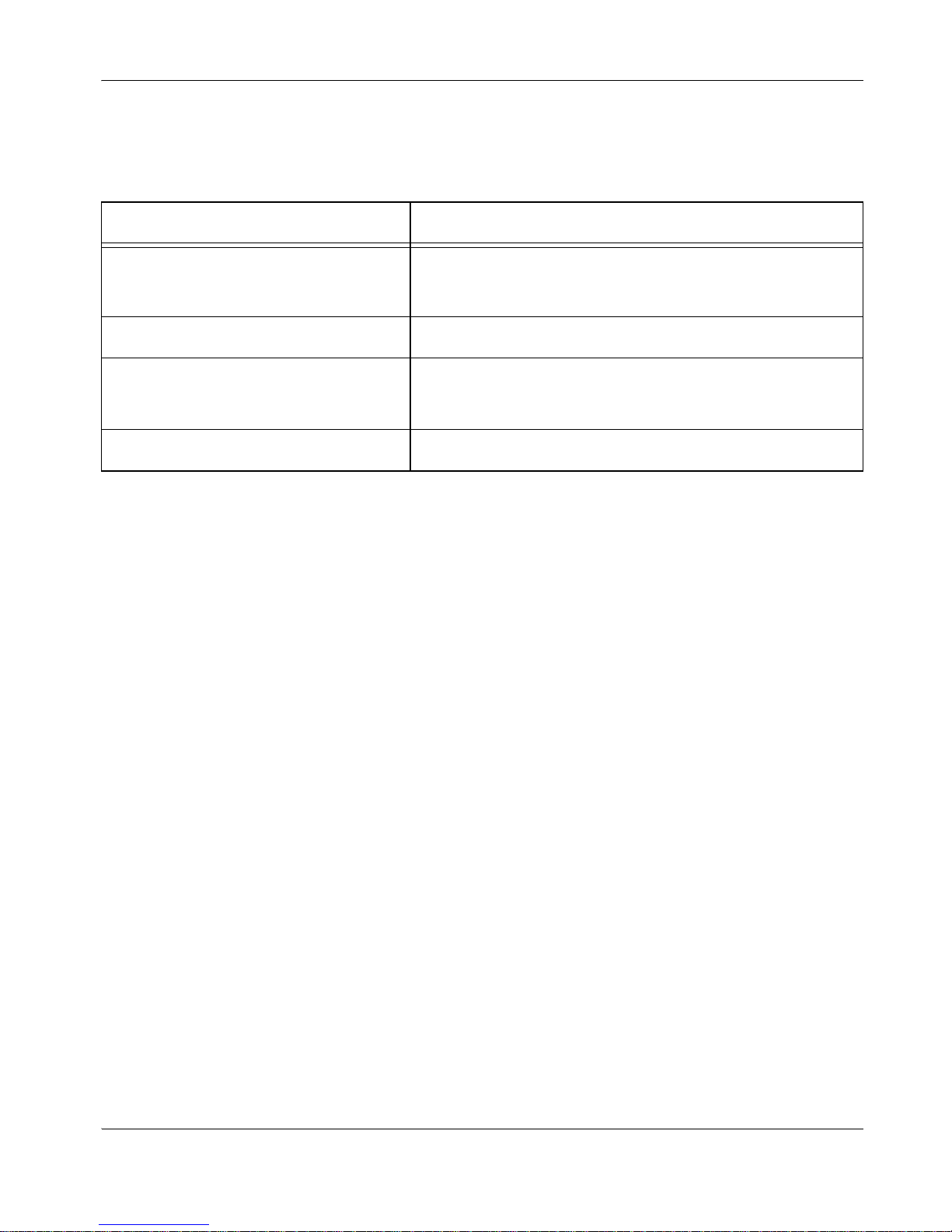
If the IP address displays an invalid value, one of the following conditions may be occurring:
Poor Quality Display
If you have poor quality or unreadable data on the LifeSize Phone display, adjust the User
Preferences : LCD Contrast setting. The default setting (6) is recommended.
If the colors on the display appear incorrect verify that the RGB cable is properly connected
to the display.
If you experience poor motion handling or visible tiling in the far end picture during a video
call, check the following:
• You have adequate bandwidth for the data rate at which you are trying to establish the
call.
• The Internet or private line connection you are using is optimized for video calls.
• The switch/router configuratio n in you r network is configured for full duplex 100-base T.
Missing Input
If you have not connected all possible video inputs, the input selection dialog displays a blue
image by default. If you select an input that is not connected, a full screen view of random
data displays. Connect the necessary input or choose a different input as described in
"Selecting Input" on page 16.
Unable to Display Presentations
If you are unable to display presentations as described in "Presentations" on page 18,
ensure you have disabled the H.245 tunneling preference. Access Administrator
Preferences : Communications : H.245 Tunneling. This preference is disabled by default.
Condition Resolution
The unit is configured to obtain an address
using DHCP and no DHCP server is
available.
Verify that the unit is plugged into a network that has a DHCP
server present.
Faulty Ethernet cable connection. Replace the Ethernet cable with a high quality cable.
The unit is configured to use a static IP
address, but no IP address has been
entered in the address field.
Identify and enter the necessary IP information if you disable
DHCP.
Network connection is unavailable. Check your network connection.
Page 38

37 LifeSize Room User Guide
Audio Issues
The following issues are related to the audio quality.
Absent Dial Tone
If you do not receive a dial tone after pressing the or key to initiate a call, ensure
the speaker volume is adjusted appropriately.
Also ensure the line out is securely connected.
An absent dial tone may also result from an unavailabl e analog phone line connecti on. If you
are connecting with PSTN, ensure the analog phone connection is secure and that it is
connected to an active phone line jack.
Problematic Sound Quality
If you are unable to hear the phone ring when an incoming call arrives, the speaker volume
may be set too low. (The LEDs flash blue to indicate an incoming call.) Adjust the volume
using the up and down volume key. If you still experience audio problems, adjust the Ring
Tone Volume preference (from the User or Administrator Preferences : Audio menu).
Muffled audio reception fro m the far side may b e caused by highly reverb erant rooms. If you
are experiencing poor audio reception, add more sound absorbency to the room and speak
in close proximity to the phone.
Adjust the priority order for your audio codec if you have chosen a low-bandwidth audio
codec to be first. Ensure that the far end caller has configured the phone correctly and is in
an acoustically benign environment. For best results, ensure the far end caller is using a
LifeSize Phone. Audio quality from your LifeSize Room system will vary when calling a nonLifeSize audio or video unit. LifeSize Room will use the audio codec that the non-LifeSize
system supports.
Degradation in the audio quality can also be caused by faulty microphones or dust and
debris accessing the phone. Do not use any kind of liquid or aerosol clea ner on the phone. A
soft, slightly damp cloth should be sufficient to clean the top surface of the phone if
necessary.
If you experience a high frequency buzzing sound when you plug your LifeSize Room
system into external powered speakers, you may be experiencing common mode noise. To
eliminate this condition, insert an Isolation Transformer (also called a Ground Loop
Eliminator) from your local electronics store between the LifeSize Room output and the
loudspeaker input.
Page 39

LifeSize Room User Guide 38
Distorted Audio
Poor audio quality may result from a bad network connection. Ensure that your network
connection is capable of handling the correct bandwidth; LifeSize recommends that your
network connection be capable of at least 100Mbps (100-baseT) for best performance.
Also ensure the loudspeaker is not obscured or damaged at either end of the call. Do not
stack items on top of the phone. Ensure both ends are not muted. Verify that the Audio Out
cables are properly connected to th e disp la y and that any external speaker systems are
powered and configured correctly. If an external speaker system has its own volume control,
adjust the volume to near maximum (in the range from 7-10) on the LifeSize audio output
and adjust the volume control on the external speaker system for the best results.
Power and Connectivity Issues
Network status is indicated at all times in the bottom right corner of the screen by the
following icons:
When you place a call, the Call St atus dialog displays, indicating th e current state of the ca ll
(such as dialing, ringing, connected, answered, etc.). The state of a call is also indicated in
the Call Manager dialog.
If a call does not successfully connect, verify that you have dialed a working number and
that the far end destination is powered on and available. Verify that network settings are
appropriate.
When placing a call using an IP address, if you experience one way audio or video, contact
your network administrator to make sure that the IP address you are using has access to
open network ports 1024 to 66536 to ensure that video and audio traffic is available.
Performance Issues
If you are experiencing performance issues, unplug the display a nd plug it back in. If an error
message displays, indicating you are using an unsupported monitor, connect to a different
display with a supported resolution. Refer to the LifeSize Room Release Notes for a list of
supported displays with this release.
Indicator Description
Green The network is ready and available.
Yellow The network is initializing or connecting.
Red The network is unavailable.
Page 40

39 LifeSize Room User Guide
Restoring Default Settings
You may need to reset the system to its default state to correct unknown problems you may
be experiencing or to return to a known configuration.
You can reset the system from the user interface by accessing Diagnostics : System
Reset. If this reset fails or if you do not have access to the user interface, you can manually
reset the system using the Reset button on the back panel of the codec.
If power is connected to the system when you press and hold the Reset button until the LED
on the front begins to blink, release the button and the system restarts. (This is an
alternative method to power cycle the system without unplugging the power cord.)
If the system is unplugged or power is unavailable when you press the Reset button and yo u
then apply power, the red LED illuminates and one of the following occurs:
• If you press the button for more than 5 seconds but less than 10 seconds, the LED
flashes and the system starts at the initial configuration and resets values to default
settings.
• If you press the button for more than 10 seconds but less than 15 seconds, the LED
flashes and the system starts using the previous installed version of software.
• If you press the button for more than 15 second s, the LED flashes and the system start s
and stops in diagnostic mode. Contact Customer Support for assistance with
diagnostics.
 Loading...