

Page 1

Lifesize® Icon™ Guide
May 2014
Lifesize Icon 600
Lifesize Icon 800
Page 2

Lifesize Icon Video Systems
Congratulations on joining Lifesize for the ultimate video conferencing experience!
Learn More About Your System
Lifesize Icon Guide 2
After installing your system, complete additional setup
tasks, such as changing default passwords and configuring
firewalls.
Then, start placing calls. You can also manage your calls,
share data, and create recordings.
Advanced preferences are available for additional
configuration.
Perform regular maintenance, such as software upgrades,
restoring default settings, and troubleshooting.
You can optionally use shell commands to control your
system with the Icon API.
Deploying Y our Icon V ideo System
Using Your Icon
Preferences
Maintaining and Troubleshooting
Icon Video System API
Extend the Capabilities
When these Lifesize products are integrated with your Icon system you can do the following:
Lifesize Cloud A cloud-based video service that supports desktop and mobile video
collaboration with your Icon.
UVC ClearSea Supports desktop and mobile video collaboration with your Icon.
UVC Multipoint A flexible capacity MCU allowing you to access calls hosted by the
bridge directly from your Icon.
UVC Video Center Provides video recording and publishing directly from your Icon.
UVC Manager Enables IP management of devices. Calls scheduled on UVC Manager
appear in your Icon schedule.
UVC Transit Provides a firewall and NAT traversal solution that enables video calls
within and across enterprises and organizations.
UVC Access A standalone H.323 gatekeeper that provides address translation,
network access control, bandwidth management, and routing
management for H.323 calls to gateways, video systems, and MCUs.
Lifesize Bridge Enables multiway video conferences. You can access calls hosted by
the bridge directly from your Icon.
Read more about Integrations.
To access the full set of features available with your Icon video system, your environment must include
UVC Platform with the UVC suite of applications. Refer to the documentation that accompanies these
products for detailed configuration information.
Related information is available from lifesize.com/support.
Page 3
Lifesize Icon Guide 3
Section 1: Deploying Your Icon Video System
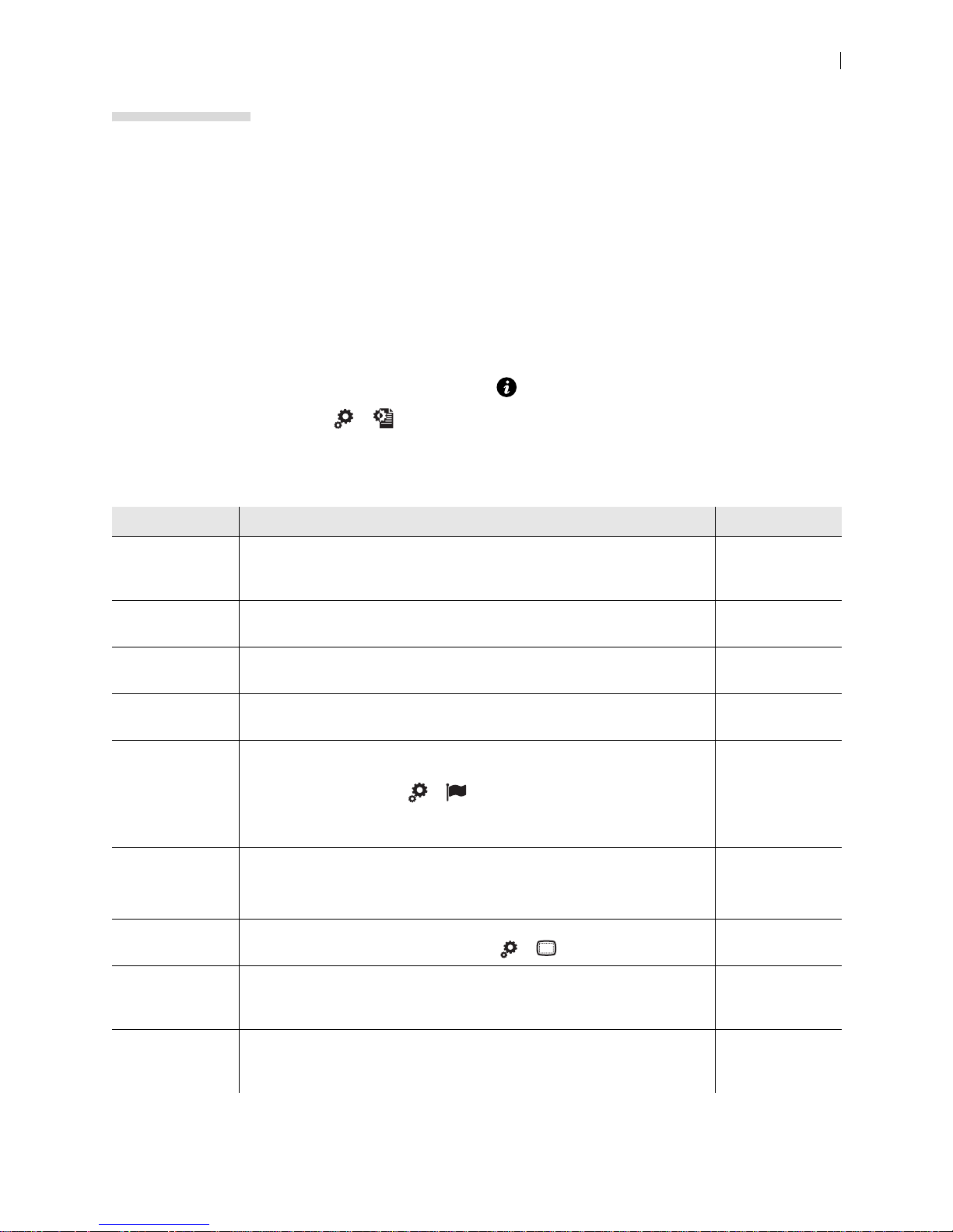
Configuration Overview
When you first install your system, a wizard directs you to configure the language, network settings, and
time zone. You can also choose to connect your Icon to the Lifesize Cloud service at this time.
After installation, configure your video system:
1. Open a web browser.
2. Navigate to the system IP address. This appears in on the main screen.
Lifesize Cloud users: select >
to view the IP address.
3. To learn about your system’s configuration preferences, click Help.
After installation you can configure the following:
Configuration Description Read More
Lifesize Cloud If you did not connect your Icon to Lifesize Cloud during initial
configuration, reset your system to associate it with your Lifesize Cloud
account.
Integrations Integrate your video system with Lifesize Cloud, the Lifesize UVC suite of
applications, and Lifesize Bridge.
Administrator
passwords
Date and time BROWSER: Set the system date and time and time zone in Preferenc es >
Language BROWSER: Select the language for the system’s interface in Preferences
System name BROWSER: Define the system name in Preferences > System.
BROWSER: Manage administrator passwords in Preferences >
Passwords.
Date and Time.
> Appearance.
REMOTE CONTROL: Select > .
NOTE: To change the language of your system’s web interface, select
Language in the sign-in screen of the web interface.
Lifesize Cloud users: Y our system name is defined through Lifesize Cloud
when you connect the Icon to the service.
Connecting to
Lifesize Cloud
Integrations
System Access
and Passwords
Help
Help
Help
Safe area REMOTE CONTROL: If the day, date, and time are not fully visible in the
upper right corner of your display, select > to adjust the safe area.
Dual displays BROWSER: If your video system is connected to two displays, select your
display configuration in Preferences > Appearance > Physical Display
Arrangement.
H.323 BROWSER: If you are using H.323 gatekeepers and want to place calls
using a name or extension with the H.323 protocol, configure your Lifesize
system to use H.323 in Preferences > H.323.
Help
Dual Displays
Help
Help
Page 4
Lifesize Icon Guide 4
Configuration Description Read More
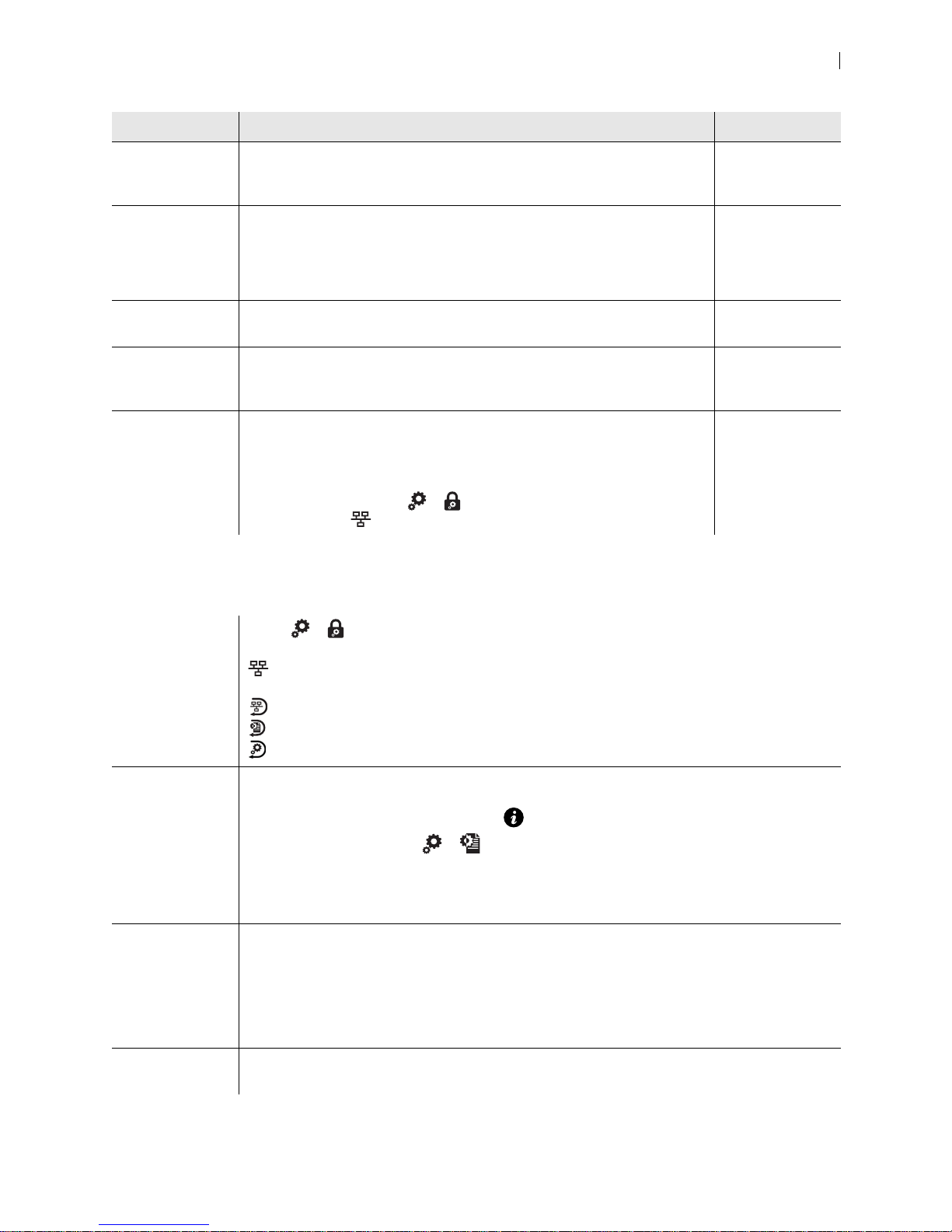
SIP BROWSER: If you are using SIP servers, configure your Lifesize system to
use SIP in Preferences > SIP Registrar 1 and Preferences > SIP
Registrar 2.
Calls, audio, and
video
BROWSER: Configure call, audio, and video pref erences:
• Preferences > Calls
Help
Help
• Preferences > Audio
• Preferences > Video
Firewall Configure your video system for firewall traversal. Configuring Your
Firewall
Automatic
provisioning
DHCP By default, DHCP is enabled on Lifesize systems. If you disable DHCP,
Enable your video system to discover a provisioning server and to
configure itself with settings that are specified on the server.
you must specify the system’s IP address, subnet mask, and default
gateway.
BROWSER: Preferences > Network
REMOTE CONTROL: Select > and enter the passcode (by default,
1234) to access .
Provisioning Y our
Icon through
UVC ClearSea
Lifesize Icon
Installation Guide
System Access and Passwords
Remote control Select > and enter the passcode (by default, 1234) to access a limited set of
administrator functions from the video system’s display:
Enable or disable DHCP. When DHCP is disabled, you can set the IP address, netmask,
default gateway, and address of the static DNS server.
Reset network settings.
Reset all settings.
Revert to the alternate software version and reset all settings to their default values.
Browser Open a web browser and enter the IP address of the Lifesize system. Sign in with administrator
credentials. The default username and password are admin.
The IP address of the system appears in on the main screen.
Lifesize Cloud users: select > to view the IP address.
By default, remote management of a Lifesize video system over HTTP is enabled at
Preferences > Security > Enable Remote Management Over HTTP.
CAUTION: Disabling HTTP signs you out and prevents you from signing back in to the system.
SSH Sign in with administrator credentials in an SSH session and enter commands to manage your
Lifesize system remotely. The default username and password are admin. Read more at Icon
Video System API.
By default, remote management over SSH is enabled at Preferences > Security > Enable
SSH Access.
CAUTION: Disabling SSH prevents you from managing the system remotely over SSH.
UVC Manager With UVC Manager, administrators can manage your Lifesize video system and other video
systems across the enterprise.
Page 5
Lifesize Icon Guide 5
Sign in to your video system from a web browser and navigate to Preferences > Passwords to manage
passwords:
User Access Username Default Password
Administrator Browser, SSH admin admin
Remote control through the video system’s display none 1234
Support Browser, SSH support support
Passwords can be up to 16 characters in length and contain any combination of the numbers 0-9, the
letters a-z and A-Z, and the symbols * (star) and # (pound). The p asscode must be o ne to 32 characte rs in
length and contain any combination of the numerals 0-9.
You cannot change the username.
Integrations
You can integrate your Icon with Lifesize Cloud, the UVC suite of applications, and Lifesize Bridge.
Available options depend on the applications configured in your environment:
Option Appears when integrated with... Configuration
Schedule UVC Manager Manage your video system in UVC Manager.
Directory Lifesize Cloud Connecting to Lifesize Cloud
UVC ClearSea Provisioning Your Icon through UVC ClearSea
Integrating Icon with UVC ClearSea
UVC Manager Manage your video system in UVC Manager.
A directory server Configure the integration in Preferences > Directory.
Meetings Lifesize Cloud Connecting to Lifesize Cloud
UVC ClearSea
(Your system registers to UVC
ClearSea over H.323.)
UVC Manager Manage your video system in UVC Manager.
UVC Multipoint or Lifesize Bridge Configure the integration in Preferences > MCUs >
Record UVC Video Center Configure your system to record to UVC Video Center
Call escalation Lifesize Cloud Connecting to Lifesize Cloud
UVC ClearSea Provisioning Your Icon through UVC ClearSea
Enabling Icon Support for Lifesize MCU Conferences
Enable MCU Integration.
in Preferences > Record and Stream.
Integrating Icon with UVC ClearSea
Global
search
UVC ClearSea Provisioning Your Icon through UVC ClearSea
Integrating Icon with UVC ClearSea
Navigation and Search
Page 6

Lifesize Icon Guide 6
Connecting to Lifesize Cloud
Once you have a Lifesize Cloud account, you can connect your Icon to the Cloud service. Associate your
Icon with your Cloud account or activate an Icon that serves as a conference room system.
After you are connected, you can take advantage of these features:
• You can download the Cloud app on all of your devices: laptop, tablet, and smartphone. Inco ming calls
ring all devices.
• Lifesize Cloud applies configuration settings to the Icon directly.
• All contacts in your company’s Cloud group are available from your Icon directory. Their online status
appears as well.
• Virtual meeting rooms configured by your Cloud account manager are available in Meetings . All
Cloud users can add meetings from their Cloud app.
• Icon can add video participants and accept multiple incoming callers to the active call.
• Software updates are automatically applied to your Icon instead of requiring you to perform a manual
update from a separate file. The system prompts you to app ly the update, allowing you to delay the
operation if you are in a call or otherwise using the system.
NOTE Learn more about Lifesize Cloud at lifesize.com.
Activating Icon on Lifesize Cloud
Connect to the Lifesize Cloud service during initial configuration. To initiate this process after installation,
reset your system to its default settings. Read more at Resetting the System.
NOTE You must have a Lifesize Cloud user account to connect your Icon to the
service.
1. When the initial configuration wizard asks you to join the Cloud service, select Yes.
2. Open a browser and navigate to the URL shown on your Icon.
NOTE You cannot activate your Icon from the system’s web interface.
3. Sign in by entering your Cloud email address and pa ssword.
Page 7

Lifesize Icon Guide 7
4. Enter the activation code shown on your Icon.
Scanning the QR code opens the Lifesize Cloud sign-in pa ge in a br owser, where your activation code
already appears.
5. You can associate an Icon to an individual user or a conference room.
Individual user Me – allows Cloud end users to associate the device to themselves.
User – allows Cloud account managers to associate the device to any user in
their Cloud group.
Conference room Use this option if the device resides in a conference room and is intended for
multiple users.
Creates a separate Cloud account for the Icon. Enter a name for the system that
will appear in the Cloud directory. Optionally, enter an email address for calling
the system.
6. From the Icon main screen, navigate to > to view the status of the system. When your Icon is
successfully activated, Ready shows for Communications > Lifesize Cloud Service.
Removing an Icon from a Cloud User Account
1. Reset your system to its default settings.
2. When the initial configuration wizard asks you to join the Cloud service, select No.
3. Cloud account manager: Sign in to the Cloud web console and remove the Icon from the Cloud user
account. Learn more in the online help available from the console.
Page 8

Lifesize Icon Guide 8
Configuring Your Firewall
This section explains how to configure your Lifesize video systems for firewall traversal, assuming you are
not using firewall traversal products such as UVC Transit or UVC ClearSea.
• If you are using UVC Transit, refer to the Lifesize UVC Transit Deployment Guide. If you are using
UVC ClearSea, refer to the Lifesize UVC ClearSea Deployment Guide.
• If your Icon is connected to Lifesize Cloud, refer to the online help available from the Cloud web
console.
Placement Behind a Firewall
Lifesize recommends that you place your system behind a firewall. Use one of the following options:
DMZ with public IP address Placing your video systems in the DMZ allows you to assign public IP addresses.
This configuration makes it easier for your system to connect with public video
systems on the Internet.
Private LAN with NAT Placing your video systems in the private LAN with Network Address Translation
(NA T) obscures their private IP addresses, but makes calls with systems outside of
your network more complicated.
Firewall Settings for Ports
At a minimum, block external or inbound access to the fo llow i ng por ts:
• 22 (SSH)
• 80 (HTTP)
• 443 (HTTPS)
• 554 (RTSP)
• 10008 (REST API service if UVC Manager manages your system)
Lifesize recommends that these ports remain open for internal administrator access. Ensure that you
change the default administrator password to be secure.
NOTE Change the administrator password in the web interface in Preferences >
Passwords. You can disable SSH and web access on the system in
Preferences > Security.
Page 9

Lifesize Icon Guide 9
Call Setup and Media Ports
To place calls to other systems through the firewall, you must configure your firewall to allow incoming and
outgoing traffic to the system through the following:
UDP port 1719
TCP port 1720
UDP port 5060 SIP call negotiation.
TCP port 5060 SIP call negotiation if TCP signaling is enabled for SIP calls.
TCP port 5061 TLS signaling in SIP calls if TLS signaling is enabled.
Required TCP and
UDP ports
Gatekeeper registration.
H.323 call negotiation.
NOTE: TLS is the only transport that is supported for encrypted calls.
Range specified in Preferences > Network > Reserved Ports.
Restricting Reserved Ports
To place calls to other devices through a firewall, you must configure your firewall to allow incoming and
outgoing traffic to the Lifesize system through the reserved ports. Users placing calls through a firewall to
systems with public IP addresses may experience one-way audio or video if the firewall is not properly
configured to allow two-way audio and video traffic.
By default, Lifesize systems communicate through TCP and UDP ports in the range 60000 - 64999 for
video, voice, presentations, and camera control. Lifesize systems use a subset of these ports during a call.
NOTE The minimum number of required ports is 100.
To minimize the number of UDP and TCP ports that are available for communication, restrict the range by
changing values in the browser in Preferences > Network > Reserved Ports. Lifesize recommends that
the range you choose, if other than a subset of the default range, begins with a port number greater than
49151. The range must start with an even number and end with an odd number to include an even number
of total ports. For a range that starts at 62000, set the lower end to 62000 and the upper end to 62099 to
allocate a range of 100 ports, the minimum.
NOTE Changing the values in Reserved Ports causes the system to restart.
Page 10

Lifesize Icon Guide 10
Using Lifesize Systems in a Private LAN with NAT
If you choose to place your video systems in a private LAN, you must use NAT to communicate with
outside systems. This may include enabling static NAT on your Lifesize system.
On your firewall, whether standalone or built in to your router, you must complete one of the following
tasks:
• Use 1:1 NAT and open the Call Setup and Media Ports over that connection bidirectionally with an
access list.
• Forward the Call Setup and Media Ports to your Lifesize system.
Refer to Restricting Reserved Ports and your firewall vendor's documentation for more informatio n.
Enabling Static NAT
NAT enables communication between devices on your LAN that have private IP addresses and devices
that are accessed through a public IP network. Static NAT ensures that the same public IP address always
maps to a system’s private IP a ddress so that data from the public network intended for the private system
can be routed to the system reliably.
If you are using static NAT to associate a public IP address with the private IP address of your Lifesize
system, you must configure your Lifesize system to work with your static NAT server. From a browser,
navigate to Preferences > Network and select Static NAT. Enter the public IP address, hostname, or fully
qualified domain name of your system in NAT Public IP Address.
NOTE You cannot upgrade the system from a web browser outside a firewall when
static NAT is enabled. Instead, perform the upgrade from within the firewall.
Testing your NAT Environment
If your firewall does not employ a feature set that performs H.323 or SIP NAT, you must enable NAT on
your private Lifesize system.
1. Place a call from a system on the Internet to your system in the private LAN. If your private system
connects within the first 2 seconds after answerin g, your NAT configuration is working properly. If the
call does not connect after answering and disconnects after 30 to 50 seconds, the reserved port
settings on your codec do not match the settings on your firewall. Ensure that the system and firewall
settings for UDP/TCP ports match.
2. If you still cannot place a successful call, you may have to disable the stateful packet inspection
feature on the firewall. Some firewall vendors may call this feature dynamic packet filtering. Refer to
your firewall vendor's documentation for more information.
Page 11

Lifesize Icon Guide 11
Provisioning Your Icon through UVC ClearSea
UVC ClearSea allows Icon to discover a provisioning server and to configure itself with settings that are
specified on the server. When auto provisioning is enabled, UVC ClearSea functions as the provisioning
server. Whenever your device discovers this server, it retrieves the hosted configuration settings and
applies them locally.
NOTE Automatic provisioning requires Icon to discover the provisioning server . Re ad
more at Discovering the Provisioning Server.
You can use one of the following options to provision Icon through UVC ClearSea:
OPTION 1: Register your Icon to
UVC ClearSea over H.323 or
SIP.
OPTION 2: Integrate Icon with
UVC ClearSea (using SIP only)
Select >
to view the auto provisioning status in the Communications section of the table. If your
Lifesize MCU conferences appear in
Meetings on your Icon.
Icon applies configuration settings from
UVC ClearSea to enable multiway calling.
Enabling Icon Support for
Lifesize MCU Conferences
Integrating Icon with UVC
ClearSea
system was provisioned successfully, the IP address of the provisioning server appears.
If no explicit ports are available, Icon attempts to communicate through the following default ports:
• HTTP requests are sent to port 80. Failed requests revert to port 8180.
• HTTPS requests are sent to port 443. Failed requests revert to port 8181.
Enabling Icon Support for Lifesize MCU Conferences
This configuration allows Icon to dial in to bridge conferences through UVC ClearSea. The managed MCU
populates Meetings
Complete the following prerequisite steps on UVC ClearSea:
1. Add an MCU in Manage > MCUs. Select Enable MCU Integration.
on Icon.
2. Create a user account for your Icon in Manage > Users.
a. Users registering with SIP or H.323 devices must use local credentials.
b. Enter the device’s IP address in UVC Auto Provisioning.
3. Add a call routing rule in Manage > Call Routing that forwards the dial string to the MCU address. The
forwarding destination uses the format :
<dialstring>@<mcuIPAddress>
Page 12

Lifesize Icon Guide 12
When Icon discovers the provisioning server, Icon retrieves the following configuration settings from UVC
ClearSea and applies them locally:
Icon Preferences Description
Directory Registers to the directory server in UVC ClearSea.
Uses the credentials from UVC Address Book in the Icon account you created in
UVC ClearSea (in Manage > Users).
H.323 Enables H.323 and registers to the gatekeeper in UVC ClearSea using the
following settings:
• Sets Name and Extension to the user ID and extension for the Icon account
you created in UVC ClearSea.
• Sets Gatekeeper Mode to Manual.
• Sets Gatekeeper Address to the IP address or domain name for UVC
ClearSea Server.
• Sets Gatekeeper Username and Gatekeeper Password to the user ID and
password of the Icon account you created in UVC ClearSea.
SIP Enables SIP.
MCUs Uses a Lifesize MCU integrated with UVC ClearSea.
Uses the IP address for the UVC ClearSea Server and the user ID and password
of the Icon user account you created in UVC ClearSea.
Registering Icon to UVC ClearSea through the SIP Registrar
Lifesize recommends that you register Icon over H.323 or SIP, not both. If you regi ster the device over SIP,
keep H.323 enabled.
1. Navigate to Preferences > SIP Registrar.
2. Enter the user ID of the Icon account you created in UVC ClearSea in SIP Username.
3. Enter the user ID and password of the Icon account you created in UVC ClearSea in Authorization
Username and Authorization Password.
4. Enter the IP address or domain name for UVC ClearSea in Registrar Hostname and Proxy
Hostname (if you use a SIP proxy).
Integrating Icon with UVC ClearSea
Integrating your Icon with UVC ClearSea provides th e followin g fe at ur es:
• Icon registers to UVC ClearSea over SIP and uses configuration settings fo r the Icon user directly from
UVC ClearSea Server.
• Icon can add video participants and accept multiple incoming callers to the ongoing call.
• UVC ClearSea contact s are available in Icon. A cont act's online st atus appears in the directory in Icon.
Page 13

Lifesize Icon Guide 13
Complete the following prerequisite steps on UVC ClearSea:
1. Add an MCU in Manage > MCUs.
2. Create a user account for your Icon in Manage > Users.
a. For automatic provisioning, users must use local credentials.
b. Enter the device’s IP address in UVC Auto Provisioning.
c. Select Enable ClearSea Integration.
3. Add a call routing rule in Manage > Call Routing that forwards the dial string to the MCU address. The
forwarding destination uses the format :
<dialstring>@<mcuIPAddress>
When Icon discovers the provisioning server, Icon retrieves the following configuration settings from UVC
ClearSea and applies them locally:
Icon Preference Description
UVC ClearSea Username
UVC ClearSea Password
UVC ClearSea IP Address Uses the IP address of the UVC ClearSea Server.
Uses the user ID and password of the Icon account that was created in UVC
ClearSea.
NOTE: If the Icon account does not use local credentials, enter the LDAP
password.
Because Icon is integrated with UVC ClearSea and relies on the server’s configuration, you are restricted
from editing MCU, H.323, and SIP preferences. Additionally, directory preferences are not set on Icon, and
Meetings does not appear.
Discovering the Provisioning Server
A device attempts to discover the provisioning server through the following methods:
DHCP option 157 Retrieves the IP address of the server. Read more in the Lifesize
DNS, based on local
search domains
(Icon only)
Update the settings
manually (Icon only)
Devices use a preconfigured DNS name that
represents the provisioning server.
This option overwrites any IP address for the
provisioning server that might have been obtained
through the DHCP or DNS options. Use this method
when you have little or no control over the DHCP and
DNS servers.
UVC ClearSea Deployment
Guide.
Sign in to your Icon from a
browser and select Maintenance
> Auto Provisioning.
Page 14
Section 2: Using Your Icon
Lifesize Icon Guide 14
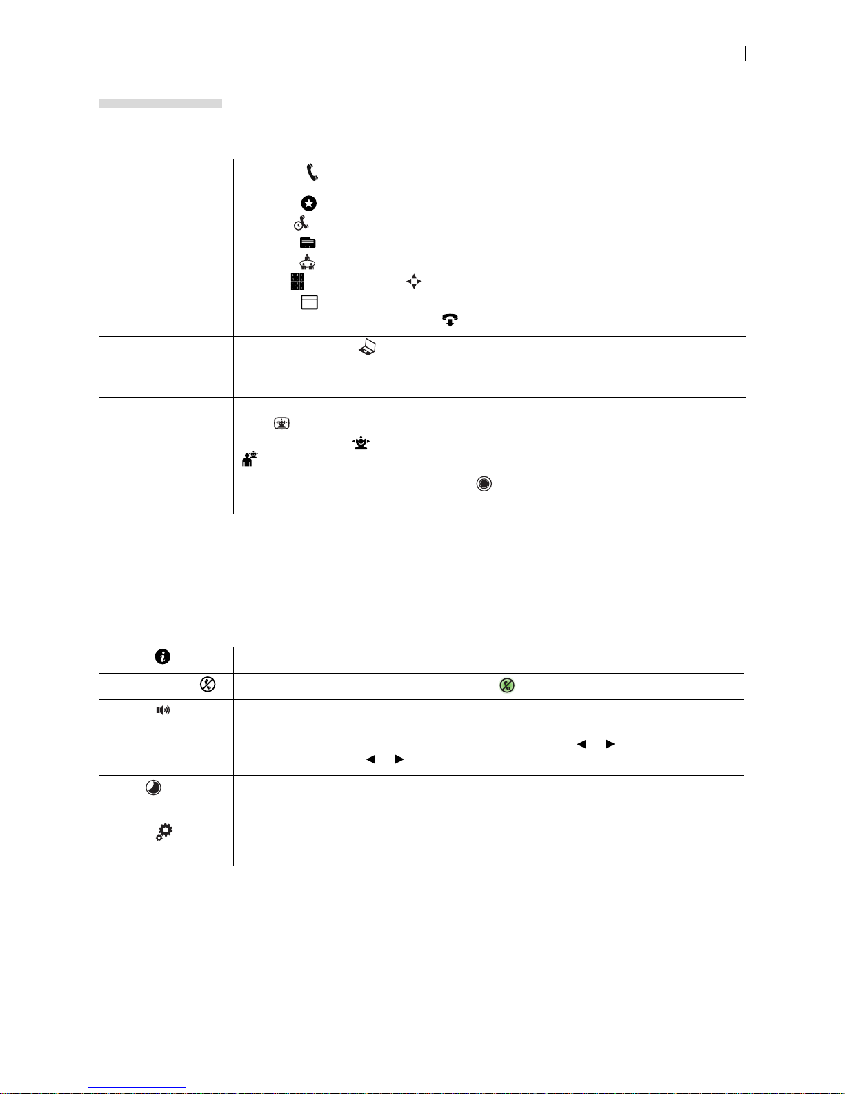
Placing, answering,
and ending a call
Initiating a
presentation
Controlling a near
or far end camera
Select Call and navigate to one of the available calling
options:
Favorites
Recents
Directory
Meetings
Keypad (phone) or Dialer (video system)
Schedule
Select Answer to answer a call and to end a call.
Select Presentation .
If you connect a laptop to a video input on the system during a
call, a presentation starts automatically.
To adjust the near end camera when the system is idle, select
View .
During a call, select
to adjust the near end camera. Select
5
Placing a Call
Managing Your Video
System In a Call
Initiating a Presentation
Camera Control
to adjust the far end camera.
Creating a
recording
With UVC Video Center configured, select . Recording with LifeSize
UVC Video Center
When your Lifesize video system is idle, the screen shows video from your camera. When the Lifesize
video system is asleep, the screen is black. An incoming call, showing a presentation, or pressing any
button on the remote control activates the system. Point the remote control at the IR receiver (located on
both the camera and the codec), not the screen, and tap a button to activate the system.
Additional options include:
My Info Shows the system name and numbers that callers use to dial into the video system.
Do Not Disturb Select to reject incoming calls. When enabled, appears.
Volume Opens a volume navigation bar.
REMOTE CONTROL: Select a volume level from 0 to 100. The level represents the volume as
a percentage. Use the remote control to adjust the level. Tap or to adjust the level in
1% increments. Press or to rapidly and continuously adjust the volume.
Sleep Select to put the video system (including camera and display) to sleep.
Read more at Sleep.
System Select to show system status and information.
Read more at System Options.
Page 15

Lifesize Icon Guide 15
Sleep
Select to put the system, camera, and display to sleep. The video system automatically sleeps under
the following conditions:
• Ten minutes elapse without user interaction.
• A voice call connects.
Tap on the phone or any key on the remote control to wake the system. When the system wakes, one
of the following options is highlighted, depending on the state of the video system:
– A system issue is present. Select for more information about the issue.
– The do not disturb feature is enabled.
– A call scheduled on UVC Manager is available on your video system.
– No other conditions are present.
Navigation and Search
Your Ico n shows call entries and other system information in lists.
Navigate information with the remote control as follows.
Navigate to the top
or bottom of a list
Search call entries Tap to open a search box to locate call entries.
When you select Russian for the language of the video system’s display, the search uses the Cyrillic
alphabet. Select using your phone and abc using the remote control to show the Latin alphabet.
If your Icon is integrated with UVC ClearSea, select to search all UVC ClearSea entries, not just the
entries in your group. Add a global entry to your Favorites for quick access. As you enter your search
string, the results are filtered to match any word in an entry’s name that starts with the filter string. Entries
from the global directory are denoted with .
Tap to quickly navigate to the top or bottom of the list.
A bar to the right of the list shows your current position and the total number of entries in
the list.
As you select values, the list is filtered to match any word in an entry’s name that starts
with the filter string. Search box options include:
• Tap to delete a value in the search box.
• Select the # symbol to represent any numeral.
• Select the symbol to insert a space between search entries, allowing you to use
multiple words in your filter.
Page 16
Lifesize Icon Guide 16
Placing a Call
Place a call using one of the following methods.
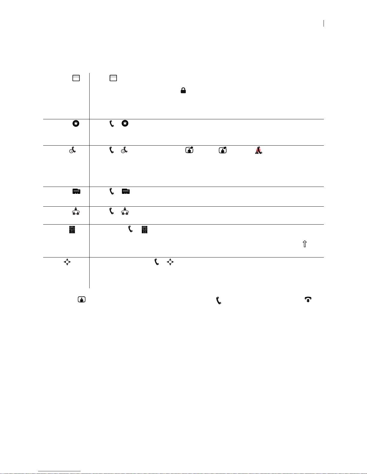
Schedule Select to show upcoming calls that UVC Manager has scheduled for your video system.
Details about the call can include the start time, title, description, and participants. Calls that
require a passcode show a lock icon . The schedule also shows time periods during which no
calls are scheduled.
A call begins at its scheduled start time and connects the participants either automatically or
after one or more of them accepts an invitation to join the call.
Favorites Select > to show your Favorites. Select an entry in the list to dial the number.
REMOTE CONTROL: Additional options include Advanced Dialing and Remove or Remove All
(to manage the entries in Favorites).
Recents Select > to show recently dialed , received , or missed calls. Select an entry to
dial the number.
REMOTE CONTROL: Additional options include Advanced Dialing, Add to Favorites, and
Remove or Remove All (to manage the entries in Recents).
Recents is limited to 50 entries.
Directory Select > to show entries. Select an entry to dial the number.
REMOTE CONTROL: Additional options include Advanced Dialing and Add to Favorites.
Meetings Select > to show available calls. Select an entry to dial the number. Read more at Joining
a Meeting.
Keypad PHONE: Select > to enter calling information manually. As you enter each character, the
corresponding touch tone is audible for the values 0-9, #, and *.
Select abc to open a keyboard to enter alphabetic characters. Select the shift character to
enter an uppercase letter. Select the shift character twice for caps lock.
Dialer REMOTE CONTROL: Select > to enter calling information manually. Navigate to advanced
5 5
options to enter alphabetic characters or select a call bandwidth or protocol. The list of available
bandwidth values adjusts to the maximum bandwidth preference set by your administrator.
Similarly, only enabled call protocols appear.
A video icon represents a video call in progress. A voice icon represents a voice call. Select to
end the call.
Available calling options also depend on the applications configured in your environment. Read more at
Integrations.
Page 17

Lifesize Icon Guide 17
Joining a Meeting
Select > to show available meetings. Details about the meeting can include the start time, meeting
name, and description. Calls that require a passcode show a lock icon .
The status for a meeting can be one of the following entries:
Live The meeting has started.
Live in <minutes> The meeting starts within 10 minutes.
Ready The meeting is open to participants, but has no participants yet.
Active Participants have already joined the meeting.
If an active meeting is full, the bridge does not accept new participants.
Unavailable No resources are available.
Full No ports are free because the conference is full.
Select an entry from the list to join the meeting. If the meeting has not yet started, a counter shows the time
remaining until the meeting is live. You can join the meeting ten minutes before the start time; the bridge
connects you automatically when the meeting is live.
Including Multiple Callers in a Call
In multiway calls, video composited from the external MCU appears on each caller’s display . Requirements
for multiway calling include:
Your Icon is integrated with UVC ClearSea and a supported
Lifesize MCU.
Your Icon is connected to Lifesize Cloud. Connecting to Lifesize Cloud
To add a participant to an ongoing call, select Add. Use this method also to transfer a caller: after you
add the participant, you can leave the call without ending it. To remove an individual caller, select and
the participant you want to remove.
For incoming calls, the following options are available:
• Click End + Answer to end the current call and answer the incoming call.
• Click Answer to add the caller to the current call.
• Click Ignore to ignore the caller.
If your Icon has an associated Lifesize ClearSea Client that is active and registered to UVC ClearSea, you
can select on the client for the client to join the call. This action disconnects the call on your Icon.
Integrating Icon with UVC ClearSea
Page 18
Lifesize Icon Guide 18
2
Managing Your Video System In a Call
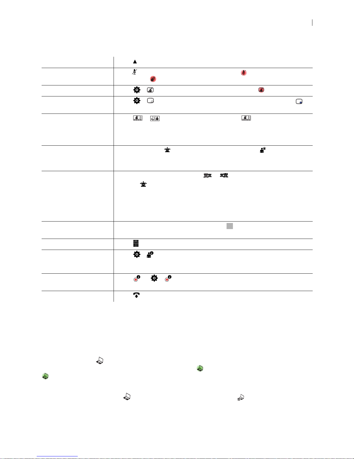
Hide onscreen text Select Hide.
Mute audio Press to mute audio to the far end. When enabled, appears. If audio at the far
end is muted, appears.
Mute video Select > to mute video to the far end. When enabled, appears.
Show picture in picture Select > to show picture in picture video during a call. When enabled,
appears.
Change the call and
presentation layout
Move the cameras During a call, select to adjust the near end camera. Select
Swap camera input If two cameras are connected, select or to swap the primary camera input.
Select or and navigate to the desired layout. is not available if the call
has only one available layout. Read more at Managing Calls Hosted by a Lifesize
MCU and Initiating a Presentation.
Lifesize Cloud users: you can change the layout only when a presentation is active.
to adjust the far
end camera.
Read more at Camera Control.
Selecting
adjusts the current camera:
• Icon 600: By default, the HD camera is the primary input, camera 1, and the DVI
camera is camera 2. Presentations are not available with two connected
cameras.
• Icon 800: By default, DVI 1 is the primary input.
Change camera input
(Icon 800 only)
Use the keypad Select to show a keypad to enter tones.
Show caller information Select > to show details about the caller, including the system name and
Show recording
information
If three or more cameras are connected, select
input.
number, and call statistics, including the call type and protocol, connection time, and
direction of the call.
Select (or > with the remote control) while recording with UVC Video
Center to show video and audio statistics of the recording stream.
to change the primary camera
End the call Select .
By default, you must manually answer or ignore incoming calls. Administrators can set Auto Answer and
Auto Answer Mute in Preferences > Calls.
Initiating a Presentation
Select Presentation to start a presentation before or during a call. If you connect a laptop to a video
input on the system, a presentation starts automatically, and appears. To stop the presentation, select
. Stopping a presentation ends any active recording.
Icon 800 only: The DVI input that functions as presentation input is represented by a numeral in the
Presentation option. Example: . To change the presentation input, select . You cannot use the
primary camera input as presentation input.
Page 19

Lifesize Icon Guide 19
If your video system is already receiving a presentation, you cannot connect a laptop and start your own
presentation without first stopping the current present ation to all callers. Further, you cannot take control of
a remote presentation.
Select from the following layout options during a call:
– Presentation input and video from the far end appear side by side.
– Presentation input and video from multiple callers appear. This layout is available with integrated
bridge calls from Meetings . For bridges that are not integrated, select < or > to choose a layout.
– Presentation input appears.
– Video from the far end appears.
If the video call does not support presentations simultaneously with video, the video system automatically
swaps the primary and presentation input s to send the present ation. The near end sho ws both the camera
and presentation input, and the far end shows only the presentation.
Camera Control
Your Ico n allo ws you to adjust a cam e ra du ring an d before a call. To prevent far end users from adjusting
the near end camera, your administrator can disable Far Control of Near Camera (enabled by default) in
Preferences > Video. To prevent far end users from using and configuring camera presets for the near
end camera, disable Far Control of Near Camera or Far Set of Camera Presets.
Pan, Tilt, Zoom, and Presets
1. From the phone, select the camera that you want to control:
> – Adjust the near end camera when the system is not in a call.
– Adjust the near end camera during a call. The near end video appears in the PIP window.
– Adjust the far end camera.
2. Adjust pan and tilt using the group of four arrows.
3. Adjust the zoom using the group of two arrows.
4. A camera preset is a predefined camera position that is associated with a numeral. Camera presets
enable you to quickly change the position of a camera during a call.
- To define a camera preset for the current camera position, press and hold a numeral until Preset
saved appears.
- To mo ve the camera to a preset location, tap the numeral.
5. To end your camera control session, select End.
Page 20
Lifesize Icon Guide 20
Recording with LifeSize UVC Video Center
With UVC Video Center configured in your environment, you can initiate a recording at any time.
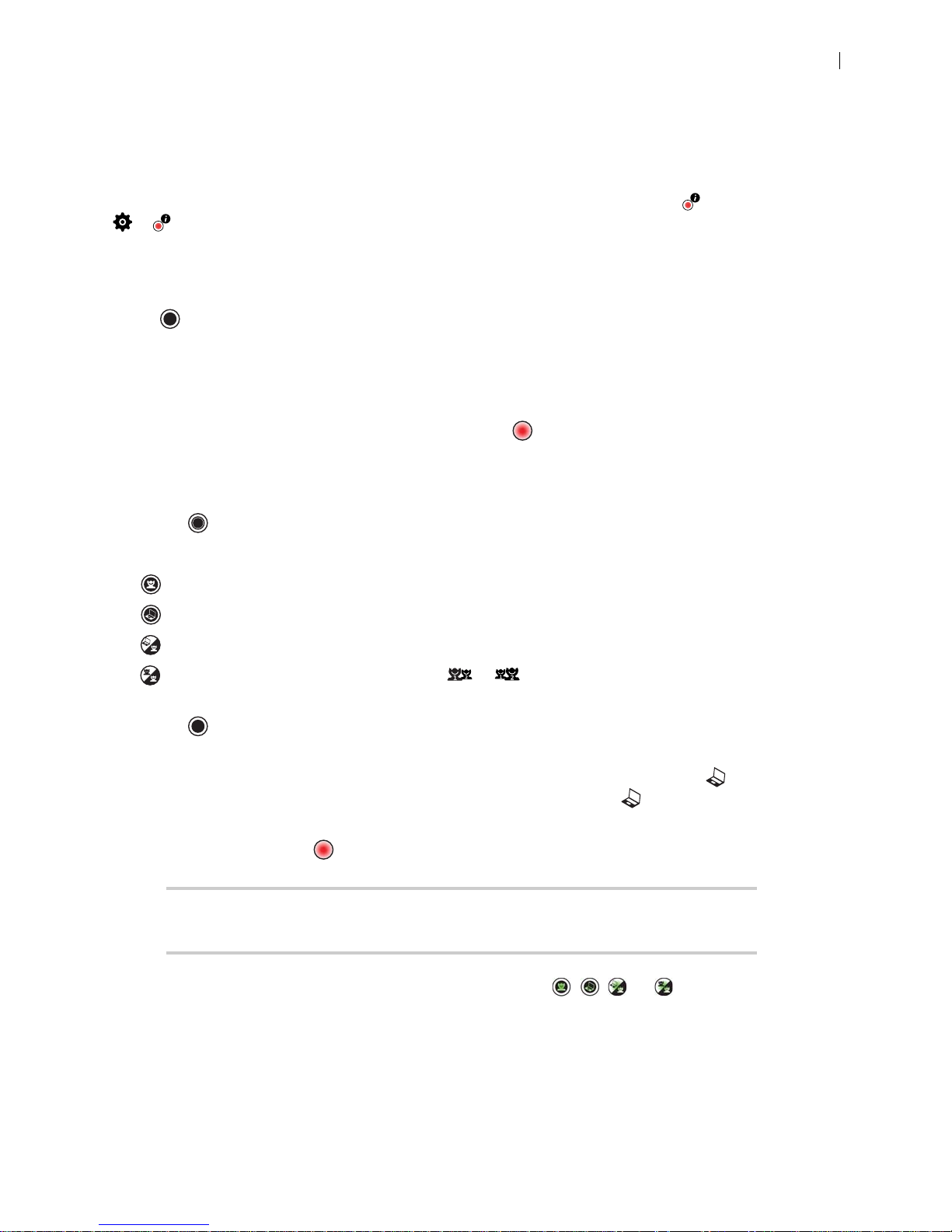
To show video and audio statistics of the recording stream during recording, select using the phone or
> using the remote control.
Recording During a Call
Select to start recording during a call. If prompted, enter a valid recording key. If successful, the
recording begins and the recording icon appears.
By default, all callers are recorded. To record only the near or far video, change the default recording
layout in Preferences > Record and Stream.
To stop a recording, end the call or presentation, or select .
Recording Outside a Call
1. Select .
2. Select from one of the available recording opt ion s to start the reco rd ing sess ion :
– Record input from the camera.
– Record input from the presentation.
– Record two streams: input from the presentation and camera.
– Record input from two cameras. Select or to select the camera that provides the primary
input. This option is available only with two connected cameras.
3. Select to start recording. If prompted, enter a valid recording key. If successful, the recording
begins and the recording icon appears.
4. Optional: If you are recording input from the camera or from a prese n tation, s elect to toggle the
input: presentation or camera. If you are recording two streams, select to toggle between recording
two streams (presentation and camera) and a single stream (camera).
5. To stop recording, select .
NOTE If you placed a call or started a presentation after th e recording started, you
can stop the recording and the session by ending the call or presentation.
6. To end the recording session, select the appropriate option: , , , or , depending on your
selection in step 2.
Page 21
Lifesize Icon Guide 21
Managing Calls Hosted by a Lifesize MCU
When UVC Multipoint or Lifesize Bridge is integrated with your Icon, scheduled and on demand
conferences available to your video system appear in > . When you join a call from Meetings , all
of the bridge layouts that are available for the curren t call scenario appear. If the call supports more than
one layout, appears. To change the call layout, select and navigate to the desired layout. For
bridges that are not integrated, select < or > to choose a layout.
When you join a call that is hosted by a Lifesize MCU that is not integrated with your Icon, select on the
phone to navigate the interface. Tap 9 to toggle help text on your display. If the Virtual Operator answers
the call, you are prompted to select a conference to join.
Tap 3 to show bridge opt i on s:
Self View The view from a participant’s camera appears on their screen.
Speaker Order When enabled, the most recent speaker appears in the prominent window.
Status Indicators When enabled, status icons appear.
Mute Video When enabled, mutes video.
Announcements Voice prompts and system sounds indicate the current system status or action
required.
Camera Control Navigation
Touch Tone Navigation
Language The language of the onscreen text and voice prompts.
T ext Inset How far the text is offset from the sides of the screen.
Toggles far end camera control and DTMF tones.
Dual Displays
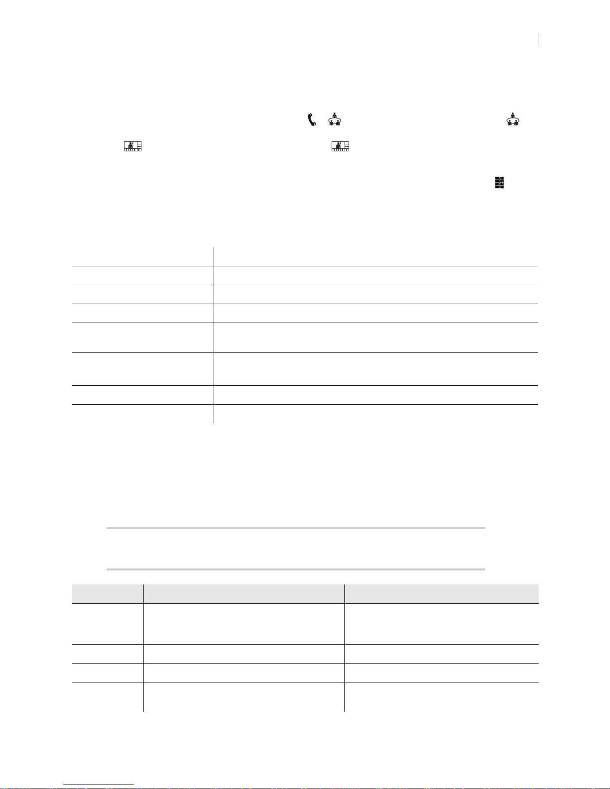
When you connect a second display, configure the dual display layout in the web interface in Preferences
> Appearance > Physical Display Arrangement.
NOTE Connecting a second display requires a license key. Contact your Lifesize
representative for details.
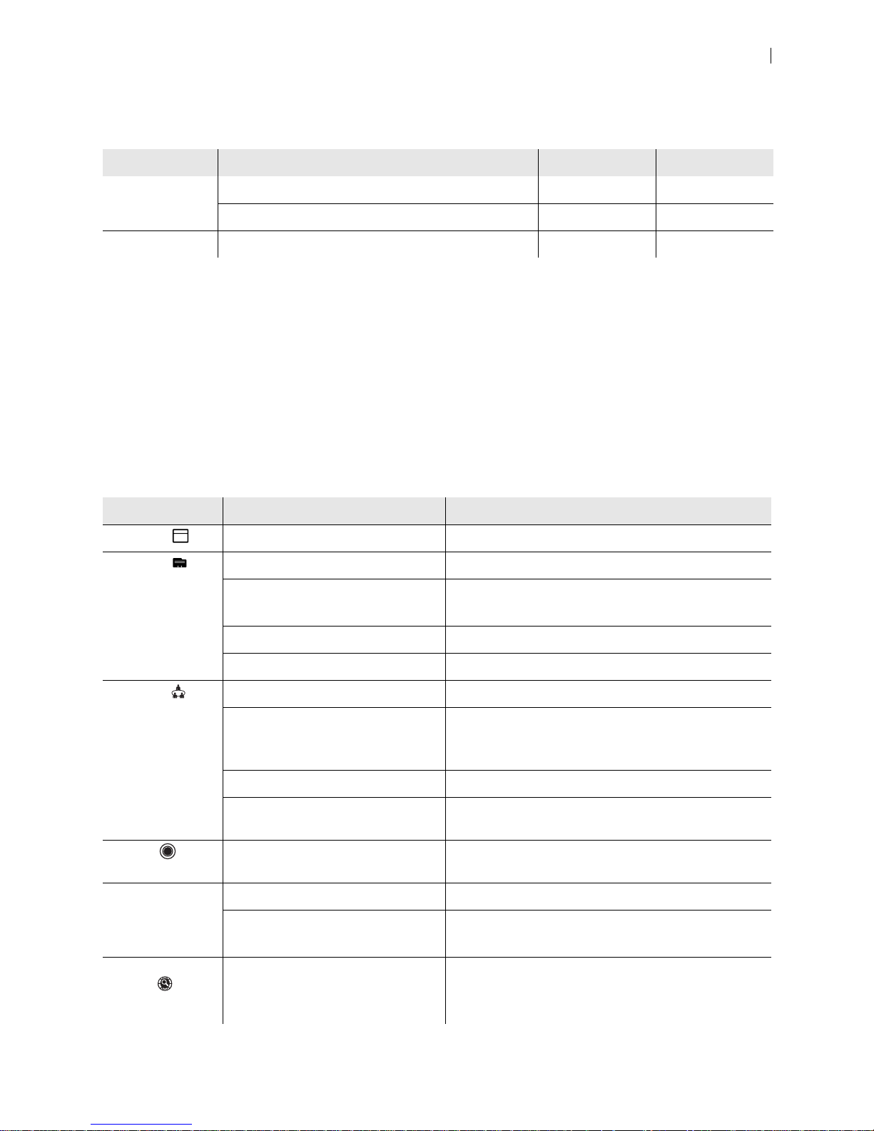
Option Display 1 Display 2
Default Cameras, callers, local presentation, in-call
presentation, composite callers + in-call
presentation
Mirror, in-call presentation
Apart Cameras, callers, local presentation Mirror, in-call presentation
Adjacent Cameras, callers, local presentation In-call presentation only
Adjacent
(Never Blank)
Similar to Adjacent, but mirrors the local view or
presentation when not in a call
Local view when in a video call without a
presentation
Page 22

Option Display 1 Display 2
Lifesize Icon Guide 22
Mirrored Cameras, callers, local presentation, in-call
presentation, composite callers + in-call
presentation
Single Cameras, callers, local presentation, in-call
presentation, composite callers + in-call
presentation
Cameras, callers, local presentation, in-call
presentation, composite callers + in-call
presentation
Deactivated
Y our Life size video system automatically con figures the second display according to your selection and the
state of the video system.
Icon 800: Audio Inputs
DVI-I Audio received from the DVI-I input is sent to the near and far end only if you configure the input
to be the primary or presentation stream.
Example: if you connect a DVR to DVI 3 and change the presentation input to use DVI 3, both
audio and video are sent to the near and far end.
Line in Analog line in is always on, eliminating the requirement to associate line in with a digital input.
Example: if you connect your smartphone to the Icon line in and press play on the smartphone,
audio is sent to both the near and far end.
If you do not want to send audio, you must control the sound at the source.
When you press mute, all audio inputs to the system are muted by default. T o con figure the system to mute
only the active microphone, sign in to your video system from a browser and set Preferences > Audio >
Audio Mute to Active Mic.
By default, the embedded audio processor for Icon 800 controls AEC, noise reduction , and automatic g ain
control. To use an external controller, turn Integrated Audio on in Preferences > Audio. When
Integrated Audio is on, Active Mic defaults to Line In.
System Options
Select for system options:
Shows the status of the system, including communications, audio, system inputs and outputs, DHCP, auto
provisioning, temperature sensors, and fan speeds.
Shows detailed system information, including communications, audio, network, system inputs and outputs,
DHCP, auto provisioning, and came ras.
Allows you to configure the safe area of your display.
Shows the system’s IP address for your administrator to configure the system. If the system is not configured
or inoperable, serial port information appears.
Select the language for onscreen text.
Shows licenses applied to the system.
After confirmation, reboots the system.
Page 23

Lifesize Icon Guide 23
Provides administrative tools. This area requires a numeric passcode (by default, 1234).
– Enable or disable DHCP. When DHCP is disabled, you can set the IP address, netmask, default
gateway, and address of the static DNS server. Select Test network to test the connection.
– Resets network settings to their default values: enables DHCP, resets the VLAN tag to 0, and enables
HTTP and SSH.
– Resets all settings to their default values and reboots the system.
– Reverts the system to an alternate software version, resetting all preferences to their default values,
and then reboots the system.
Select to sign out.
Page 24

Lifesize Icon Guide 24
Section 3: Preferences
To configure preferences, sign in to your system from a browser by entering the system’s IP address. The
default username and password are admin.
Preferences for the following categories are in Preferences:
Appearance System Log Levels Passwords System
Audio Directory Record and Stream Lifesize UVC Transit
Calls H.323 Security USB
Lifesize UVC ClearSea MCUs SIP Registrar 1 Video
Date and Time Network SIP Registrar 2
Preferences for Camera Diagnostics are in Diagnostics. The Auto Provisioning Server preference is in
Maintenance.
NOTE Available preferences depend on your configuration. For example, if your Icon
is connected to Lifesize Cloud, you cannot change the System Name
preference or preferences in H.323, SIP, MCUs, UVC ClearSea, and UVC
Transit.
Appearance
Preferences > Appearance
Preference Default Value
Language English
Physical Display Arrangement Default
Audio
Preferences > Audio
Preference Default Value
Video Call Output HD Out
Voice Call Output Phone
Icon 600 Only
Analog Mic Gain Line Level
Icon 800 Only
Integrated Audio
(Available for Icon 600 from the command line)
Off
Active Mic Auto
Audio Mute All
Page 25

Calls
Preferences > Calls
Preference Default Value
Auto Answer Disabled
Auto Answer Mute Enabled
Auto Bandwidth Enabled
Maximum Call Bandwidth 6000 kb/s
Maximum Call Transmit Bandwidth 6000 kb/s
Default Call Bandwidth 1152 kb/s
Secondary Stream Enabled
Lifesize UVCClearSea
Preferences > Lifesize UVC ClearSea
Preference Default Value
Lifesize Icon Guide 25
Enable UVC ClearSea Disabled
UVC ClearSea Username No default
UVC ClearSea Password No de fault
UVC ClearSea IP Address No default
Date and Time
Preferences > Date and Time
Preference Default Value
System Time Greenwich Mean Time (GMT) value
System Date GMT value
Time Zone GMT
Clock Format 12-Hour
NTP Server Hostname No default
System Log Levels
Preferences > System Log Levels
Preference Default Value
Syslog Server No default
Audio Debug
Communications Debug
Database Information
Page 26

Preference Default Value
License Manager Information
System Administration Information
System Information Information
System Status Information
Timer Information
User Interface Information
Video Hardware Debug
Video In Information
Video Out Information
Directory
Preferences > Directory
Preference Default Value
Lifesize Icon Guide 26
LDAP
Hostname No default
Username No default
Password No default
Base No default
Port No default
Encryption None
Page 27

H.323
Preferences > H.323
Preference Default Value
General
Use H.323 Enabled
Gatekeeper
Name Number randomly generated by the system
Extension Same value as Name
Gatekeeper Mode Off
Available Preferences with Gatekeeper Mode: Auto
Gatekeeper ID No default
Gatekeeper Authentication Disabled
Gatekeeper Username No default
Gatekeeper Password No default
Lifesize Icon Guide 27
Available Preferences with Gatekeeper Mode: Manual or Manual H.460
Gatekeeper Address No default
Gatekeeper Port 1719
Gatekeeper Authentication Disabled
Gatekeeper Username No default
Gatekeeper Password No default
MCUs
Preferences > MCUs
Preference Default Value
Enable MCU Integration Disabled
IP Address No default
Username No default
Password No default
Page 28

Network
Preferences > Network
Preference Default Value
Ethernet
IP Address No default
Subnet Mask No default
Use DHCP Enabled
Auto negotiate speed and duplex settings Enabled
Speed No default
Duplex No default
VLAN Tag 0
Gateway
Default Gateway No default
DNS
Lifesize Icon Guide 28
DNS Server 8.8.8.8
DNS Domain No default
Search Domains No default
Reserved Ports
TCP and UDP Lowest Port Value 60000
TCP and UDP Highest Port Value 64999
Network QoS
Network QoS None
Video
Video Maximum Transmission Unit (MTU) 1440
Static NAT
Static NAT Disabled
NAT Public IP Address No default
Passwords
Preferences > Passwords
Preference Default Value
Administrator Password admin
Video System Passcode 1234
Support Password support
Page 29

Record and Stream
Preferences > Record and Stream
Preference Default Value
Recorder Disabled
Recorder Hostname No default
Recorder Port 443
Recording Key No default
Default Recording Layout All Callers
Security
Preferences > Security
Preference Default Value
Enable SSH Access Enabled
Enable Remote Management Over HTTP Enabled
Lifesize Icon Guide 29
SIP Security Off
H.323 Security Off
SIP Registrar 1
Preferences > SIP Registrar 1
Preference Default Value
General
Use SIP Enabled
Identification
SIP Username Lifesize
Authorization Username No default
Authorization Password No de fault
Server
SIP Server Type Auto
SIP Registrar Disabled
Registrar Hostname No default
SIP Registration Direct
SIP Proxy Disabled
Proxy Hostname No default
SIP Signaling Auto
Page 30

SIP Registrar 2
Preferences > SIP Registrar 2
Preference Default Value
General
Use SIP Disabled
Identification
SIP Username No default
Authorization Username No default
Authorization Password No de fault
Server
SIP Server Type Auto
SIP Registrar Disabled
Registrar Hostname No default
SIP Registration Direct
Lifesize Icon Guide 30
SIP Proxy Disabled
Proxy Hostname No default
SIP Signaling Auto
System
Preferences > System
Preference Default Value
System Name Conference Room
Lifesize UVCTransit
Preferences > Lifesize UVC Transit
Preference Default Value
UVC Transit Disabled
UVC Transit Hostname No default
UVC Transit Username No default
UVC Transit Password No default
Enable for SIP Disabled
SIP Username No default
Enable for H.323 Disabled
H.323 Extension Same value as Preferences > H.323 > Extension
Page 31

USB
Preferences > USB
Preference Default Value
USB 1
Shell None
Speed 115200 b/s
Flow Control No flow control
USB 2
Shell None
Speed 115200 b/s
Flow Control No flow control
Video
Preferences > Video
Lifesize Icon Guide 31
Preference Default Value
Video Control
Far Control of Near Camera Enabled
Far Set of Camera Presets Disabled
Far Move to Camera Presets Enabled
Video Quality
Presentation Video Bandwidth 20%
Adaptive Motion Control Enabled
HD Display Resolution
HD Display Resolution Highest resolution supported by the display
DVI Display Resolution
DVI Display Resolution No default
Consumer Electronics Control
Enable CEC Disabled
Enable Sleep Disabled
Video Monitor
HDMI DPMS Mode Off
DVI DPMS Mode Off
Page 32

Camera Diagnostics
Diagnostics > Camera
Preference Default Value
IR Receiver Enabled
Anti-Flicker Auto
Auto Exposure Method Full-frame
Brightness 0
Auto Focus Enabled
White Balance Auto
Lock camera position Disabled
Auto Provisioning
Maintenance > Auto Provisioning
Preference Default Value
Lifesize Icon Guide 32
Auto Provisioning Server No default
Page 33

Lifesize Icon Guide 33
Section 4: Maintaining and Troubleshooting
This section describes how to maintain your system and use diagnostic tools for troubleshooting.
System Maintenance
Sign in to your video system from a web browser to perform system maintenance.
Save Maintenance > System Re set > System Save Saves the backup file to your
computer.
Restore Maintenanc e > System Reset > System Restore Restoring a System Configuration
Reset Maintenance > System Reset > System Reset Resetting the System
Revert Maintenance > System Reset > System Revert Reverting the System to the
Alternate Software Version
Update license keys Maintenance > License Keys Updating License Keys
Upgrade Maintenance > System Upgrade Upgrading Your System Software
Reboot Diagnostics > System Reboot Rebooting the System
Restoring a System Configuration
1. Ensure that a current, saved configuration file exists before performing a restore.
NOTE Configuration preferences and options vary across software releases.
Restoring a system configuration by using a file saved from a different
software release can produce unexpected results. Only restore a
configuration that was saved from the same software release.
2. Hang up all calls connected to the system. If calls are connected when you perform a restore, you are
prompted to continue or cancel the restore. If you continue, the system restore process terminates the
calls.
3. Select Maintenance > System Reset > System Restore .
You must have a current system configuration saved prior to executing the system restore function or
you will be unable to return to the previous state.
4. Browse to the system configuration file and click Upload.
Page 34

Lifesize Icon Guide 34
Resetting the System
1. Select Maintenance > System Reset > System Reset .
2. Optional: Enter the reason for the reset.
3. Click OK to confirm setting the system to its default state.
The system automatically reboots and the administrator password is rese t to the default value ( admin).
NOTE Y o u can also reset the system by pressing the red reset button on the back of
the codec for 10 to 15 seconds.
Reverting the System to the Alternate Software Version
1. Select Maintenance > System Reset > System Revert .
2. Optional: Enter the reason for reverting the system.
3. Click Yes.
The system automatically reboots.
NOTE Y ou can also revert the system by pressing the red reset butto n on the back of
the codec for 15 to 20 seconds.
Rebooting the System
The system reboots when you complete any of the following tasks:
Manually reboot the system. Diagnostics > System Reboot
Reset the system to its default state. Maintenance > System Reset > System Reset
Revert the system to the previous state. Maintenance > System Reset > System Revert
Restore the system to a saved state. Maintenance > System Reset > System Restore
Change the VLAN Tag preference. Preferences > Network > VLAN Tag
Change the values for the reserved ports. Preferences > Network > Reserved Ports
Upgrade the system software. Maintenance > Sy stem Upgrade
NOTE You can also reboot the system by pressing the red reset button on the back
of the codec for 5 to 10 seconds.
Page 35

Lifesize Icon Guide 35
Updating License Keys
You must have current license keys to enable the following:
• software upgrades
• dual display
NOTE The expiration date for a license key appears in Maintenance > License
Keys. Contact your Lifesize Partner for details about license keys.
If your system has HTTP access through port 80 to the Lifesize license key server, update your license
keys from a browser. Otherwise, refer to Installing a License Key Manually.
1. Navigate to Maintenance > License Keys.
2. Click Update.
If the update is successful, Success appears along with the current license keys and their expiration
dates.
Update failures might be caused by one of the following conditions:
- A current maintenance agreement for the device does not exist. Contact your Lifesize Partner to
renew your maintenance agreement.
- The system failed to connect. The server might be down or your system might not have HTTP
access. Contact Lifesize Technical Services if this condition persists and you have HTTP access,
or install a key manually following the steps in Installing a License Key Manually.
- A license key exists, but it is invalid. Contact Lifesize Technical Services.
Installing a License Key Manually
1. From lifesize.com/support click Download Software.
2. Sign in to your support account. If this is your first visit, create the account.
3. Enter the serial number of your Lifesize video system (locate d in Diagnostics > System Informati on)
and follow the instructions to obtain a license key. You might have multiple keys.
4. Download a license key.
5. Sign in to your video system from a web browser and navigate to Maintenance > License Keys.
6. Click Add and paste the license key that you obtained in step 3 in Enter License Key.
7. Click Add.
8. Repeat steps 3 through 7 for each license key listed for your video system.
Page 36

Lifesize Icon Guide 36
Upgrading Your System Software
NOTE If your Icon is connected to Lifesize Cloud, software updates are automatically
applied to your system. The system prompts you to a pply the update, allowing
you to delay the operation if you are using the system.
Before you upgrade your system software, ensure that the system meets the following prerequisites:
• A current license key for upgrading exists on the system. The expiration date for the maintenance
license appears in Maintenance > License Keys. Read more at Updating License Keys.
An upgrade fails if a current license key does not exist on the system or has expired. Contact your
Lifesize Partner to renew your maintenance agreement.
• All cameras that you intend to use with the video system are properly connected to the codec.
Cameras not connected to a Lifesize system before an upgrade may not function properly after an
upgrade.
• Terminate all calls prior to upgrading.
Lifesize recommends you save your system configuration before upgrading: Maintenance > System
Reset > System Save.
1. From lifesize.com/support click Download Software.
2. Sign in to your support account. If this is your first visit, create the account.
3. Enter your serial number (located in Diagnostics > System Information). Follow the instructions to
find the software version you want for your product, and download it to a local directory on your
computer.
4. Navigate to Maintenance > System Upgrade.
5. Click Select File to browse for the upgrade file you downloaded in step 3.
The system validates the file. To re-validate the same file or if you manually entered a path to a file,
click Validate for the verification to occur.
6. To reset the system to the original default settings, select Reset to defaults.
7. Click Upload.
The upgrade can take several minutes; do n ot disrupt the process. Duri ng an upgrade , a st atus screen
appears in a browser in which you can monitor the process of the file upload. If you close the window
before the file upload completes, the upload is cancelled.
When the upgrade is complete, the system automatically reboots.
8. Your video system is ready to use. If you selected Reset to defaults in step 6, you must first
reconfigure your system.
9. To access all options from a browser after an upgrade (or downgrade), refresh the browser before
signing in again.
Page 37

Lifesize Icon Guide 37
Troubleshooting Upgrade Failures
If attempts to upgrade software fail, follow these steps:
1. Ensure you have a valid upgrade image.
2. Reboot the system.
3. Attempt the upgrade again.
4. If a second attempt fails, note the error code returned.
5. If problems persist, contact your Lifesize Partner or Lifesize Technical Services.
Upgrade Error Codes
Following are the error codes you might receive when an upgrade fails.
Code Problem
1 An upgrade is in progress. The system supports only one upgrade at a time.
2 The image is corrupt. This typically occurs because of a bad image or errors during upload to the device.
3 The encryption signature is invalid. This typically occurs if the image is corrupt or compromised.
4 The image is missing an upgrade script. After the image has been successfully uploaded, the system
runs an upgrade script for final processing. This error indicates a failure in that script.
5 The manifest is corrupt or missing.
6 The serial number is invalid.
7 The build date is invalid.
8 The software image is for a different system type.
9 Unable to downgrade to the image version.
10 The upgrade license expired. A current license key for upgrading the system software does not exist on
the device. Contact your Lifesize Partner to renew your maintenance agreement.
11 You cannot upgrade while calls are connected.
12 A restore to defaults is required. The upgrade requires a reset. Navigate to Mainten ance > System
Reset and reset the system to its default state before proceeding with the upgrade.
13 A system error occurred.
16 Insufficient space to store the image.
17 Failed to verify the image.
18 The license server is unreachable.
19 Failed to download the upgrade image.
Page 38

Lifesize Icon Guide 38
Diagnostic Tools
System Information Details about your system, including serial numbers and versions, are available in
Diagnostics > System Information.
System Logs Save system logs to your computer in Diagnostics > System Logs.
Set log levels in Preferences > System Log Levels. Lifesize recommends using a syslog
server for integrated configurations.
NOTE: If you disable the logs for Database, System Status, Timer, and Video Hardware,
rebooting the system returns the logs to their default values.
Diagnostic Report Support personnel might request that you capture a diagnostic report from your system to
identify the cause of a problem with your system. When you are instructed to gather
information, select Diagnostics > Diagnostic Report > Generate Diagnostic Report.
Camera Use the camera diagnostics to adjust camera brightness and white balance and correct
some types of flicker. Read more at Camera Issues.
Call Records To download call history, select Diagnostics > Call Records > Download Call Records.
Read more in the video system’s online help.
System Health
Indicator
The health icon
Read more at System Health.
that appears on the main screen is an indicator of a system issue.
Troubleshooting
The following sections describe symptoms, possible causes, and potential solutions for common problems
you may encounter with your Lifesize system.
When experiencing a problem, visually inspect the unit. Ensure that the system has not been exposed to
water or heat sources or was physically damaged.
Improperly connected or loose cables are common problems with hardware units. When investigating a
system problem, first inspect the external controls and cable connections. Ensure that connections are
correct and secure and that nothing is obstructing the cables. Contact your administrator for information
about proper cabling.
System Health
From your video system’s display, navigate to > to view the status of the system, temperature, and
fans. When a system issue arises that might require your attention, the health icon appears on the main
screen. The shading behind the icon reflects the severity of the issue:
• Yellow shading indicates a warning.
• Red shading indicates a critical issue.
Page 39

System issues might include the following:
Communications Network Warning: the system is binding to the network.
Critical: the system is disconnected or no DHCP server is present.
Lifesize Icon Guide 39
Lifesize Cloud
Service
Auto
Provisioning
Lifesize
ClearSea
H.323
Gatekeeper
SIP Registrars Warning: the system is registering with the SIP registrar.
UVC Transit Warning: the system failed to connect with UVC Transit; the system is
MCU Warning: communication with the integrated bridge has been
LifeSize Phone Warning: the phone is initializing.
System I/O Active
Microphone
Warning: Your account expired; your account trial ended; you must
validate your account.
Warning: the syste m is bei ng provisioned.
Critical: provisioning failed.
Warning: the system is registering with UVC ClearSea.
Critical: the registration failed, or UVC ClearSea is unavailable.
Warning: the system is registering with the H.323 gatekeeper.
Critical: registration failed, or the gatekeeper is unreachable.
Critical: the registration failed, or the registrar is unreachable.
registering with the H.323 gatekeeper or SIP registrar.
Critical: the system failed to connect with UVC Transit; the system
failed to register with the gatekeeper or registrar.
interrupted
Warning: no active microphone is present.
LifeSize Link
Critical: an error occurred with the power to LifeSize Link.
Power
Thermal Fan Sp eed Critical: the system is overheated.
Temperature
Sensors
Warning: the system is above normal operating temperature.
Critical: the system is overheated and approaching the maximum
allowed operating temperature.
Processes System Status Critical: a process failed.
Page 40

Lifesize Icon Guide 40
Adjusting Room Lighting
Ensure that the system maintains the best possible image quality by altering the lighting and background
colors of your environment. If light levels are too low, you may consider adding artificial lighting. Indirect
light from shaded sources or reflected light from pale walls often produces excellent results.
Avoid the following:
• Direct sunlight on the subject matter, the background, or the camera lens, which creates harsh
contrasts
• Direct illumination of the subject matter and camera lens
• Colored lighting
• Harsh side lighting or strong light from above
Camera Issues
If you are unable to pan, tilt, or zoom a camera, ensure that the remote control contains two AAA batteries
that are in good working condition. Verify that no objects are obstructing the sensor on the front of the
camera and that the LED on the front of the camera flashes bright blue when you use the remote control to
perform a task.
If the camera does not show video, ensure that the camera is connected to the Lifesize system with a
camera cable in the appropriate camera input or contact your administrator.
Verify that the blue LED on the front of the camera is lit, which indicates that power is active, and reboot
the system if necessary to verify that the camera turns on. If a system reboot does not resolve the problem,
you might need to reapply power to the camera.
Administrators can also configure preferences for the following camera conditions:
• Anti-flicker
• Auto exposure
• Brightness
• Auto focus
• White balance
• Lock camera position
Read more about these settings in the online help available when you sign in to the video system from a
browser.
Packet Loss
Packet loss can result in noticeable video or audio performance issues and can be caused by signal
degradation over the network medium, oversaturated network links, corrupted packets rejected in-transit,
faulty networking hardware, and misconfigured system drivers or network applications. Refer to the
technical note Troubleshooting Packet Loss for steps you may take to address packet loss.
Page 41

Lifesize Icon Guide 41
Display Issues
If data does not appear on the display, ensure cables are properly connected on the display and that the
display cable is connected to the HD 1 output on the back panel of the codec.
If the video image and user interface appear washed out or too bright, examine your HDTV input settings
to make sure the HDTV has the appropriate resolution. Some HDTVs, particularly plasma displays, allow
you to configure the native resolution of the input device from the HDTV administration interface.
Administrators only: Sign in to the video system from a browser and navigate to Preferences > Video to
ensure that the display resolution is correct for your display.
Problematic Sound Quality
If the far side is hearing an echo or distortion, the microphone connected to your Lifesize system may be
too close to the speakers. Repositioning the microphone may solve this problem.
Poor audio reception from the far end may be caused by highly reverberant rooms. If you are experiencing
poor audio reception, add more sound absorbency to the room and speak in close proximity to the phone
or microphone.
Degradation in the audio quality can also be caused by faulty microphones.
If dust and debris are on the microphones clean the top surface of the unit s with a sof t, slightly damp cloth.
Do not use any kind of liquid or aerosol cleaner on Lifesize devices that include microphones.
Power and Connectivity Issues
If a call does not successfully connect, verify that you dialed a working number and that the far end is
powered on and available. V erify that the netwo rk is ready and available b y naviga ting to > to view
the network status.
Presentations
Administrators only: Consider disabling the secondary stream function in Preferences > Calls if your
system experiences issues with third party systems that do not support secondary streams.
Page 42

Lifesize Icon Guide 42
Section 5: Icon Video System API
The Lifesize API provides a command line based entry point for automating access and control of Icon
video systems. The API supports a REST method for accessing a set of resources, or objects, through a
fixed set of operations. API calls are made by sending a request to an API resource and specifying a
method and arguments. A formatted response details the operation’s outcome.
This section provides an introduction to the Lifesize API. More detailed documentation is available at:
https://<videoSystemIPAddress>/docs/json/
Authentication
The same authentication policies that are enforced on a browser also apply to API calls. Sign in to your
Lifesize video system through an SSH or HTTP connection over the network as follows:
1. Open a client, such as Cygwin or Putty, and enter the IP address of your Lifesize video system.
2. Sign in to the system with administrator credentials. The default username and password are admin.
Command Syntax
Commands take the following form:
<actor> <command> <parameters>
Use commas to separate multiple parameters. Show help from a command prompt as follows:
help Shows a brief introduction to using the API.
Press the Tab key. Shows a list of actors.
<actor> ? Shows commands for an actor. For example:
audio ?
<actor> <command> ? Shows help for a command. For example:
sysadmin gettimezone ?
Page 43

Copyright Notice
©2014 Lifesize, a division of Logitech. All rights reserved.
Lifesize, a division of Logitech, has made every effort to ensure that the information contained in this document is
accurate and reliable, but assumes no responsibility for errors or omissions. Information in this document is subject to
change without notice. Companies, names, and data used in examples herein are fictitious unless noted. This
document contains copyrighted and proprietary information which is protected by United States copyright laws and
international treaty provisions. No part of the document may be reproduced or transmitted, in any form or by any
means, electronic or mechanical, for any purpose, without the express written permission from Lifesize
Communications.
Trademark Acknowledgments
Lifesize, the Lifesize logo and other Lifesize marks, are registered trademarks or trademarks of Logitech. All other
trademarks are the property of their respective owners.
Patent Notice
For patents covering Lifesize products, refer to lifesize.com/support/legal.
Contacting Technical Services
Lifesize Communications welcomes your comments regarding our products and services. Refer to lifesize.com/support
for ways to contact Lifesize Technical Services.
 Loading...