

Page 1
_LifeShield-QSG-NONDSL.qxp:Layout 1 2/11/10 9:52 PM Page 1
Page 2
Start Here
GR ID EX TE ND ER
SE NSO R
SE NSO R
SE NSO R
HA NDS E T
CON SO LE
BA SE
I MP OR TA NT : F O L LO W ST EP S I N E XA CT O RD E R . D O N O T S K I P A H EA D.
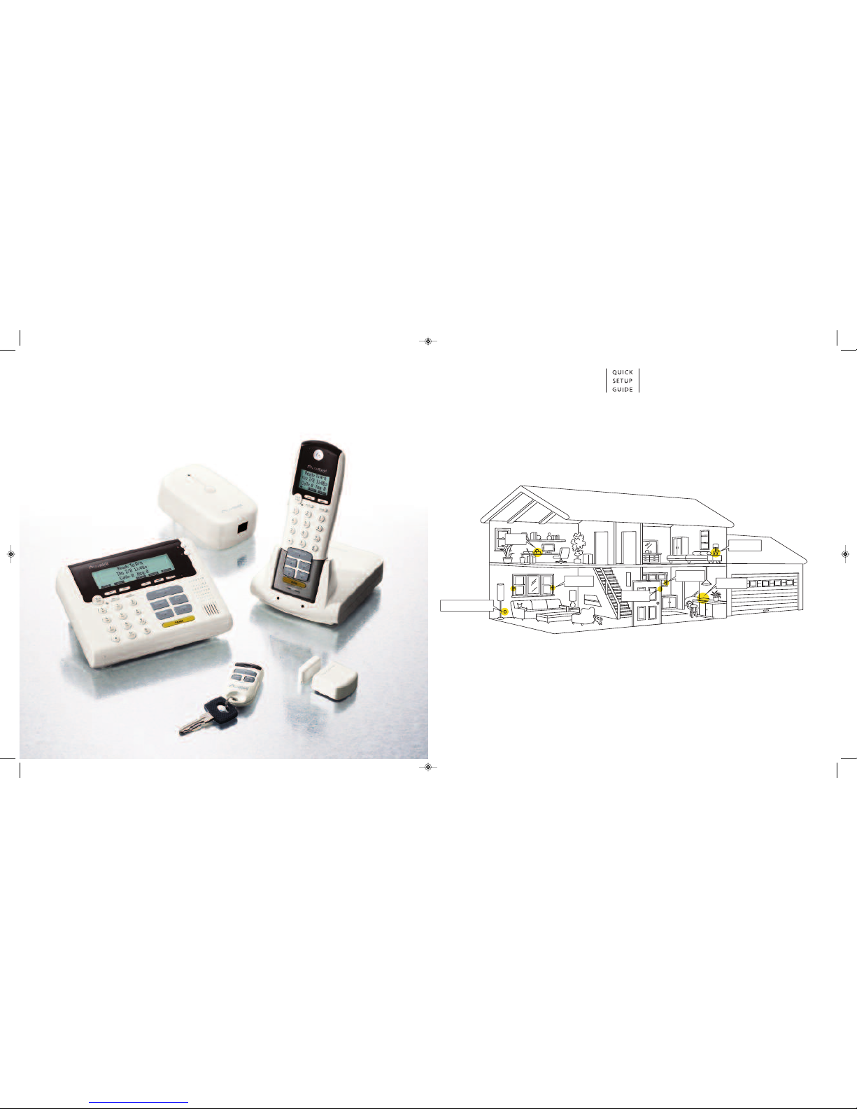
Component Placement Suggestions:
The
LifeShield Home Security
system you are about to install is wireless. To maximize wireless coverage, plan to
place the
Base, Console
and
Grid Extender
components throughout your home. Ideally, these components will be in
different rooms on interior walls. A key consideration is making sure that all
Sensors
are within approximately 30 feet
of one or more of these components.
NOW IS A GOOD TIM E TO PLAN YOUR COMP ONENT PLAC EMENT
Internet
The
Base
connects the system to the Internet. Your Internet
connection is likely located where your Modem/Router is
placed. The Internet enables remote access to your system
from
LifeShield.com
. If you are professionally monitored,
the Internet is also the primary vehicle through which
alarms and events get reported to Central Monitoring for
dispatching the proper authorities to your home.
Phone Line Back Up
If you subscribe to a phone service, the phone line enables the phone
functions on your LifeShield system. It also serves as a backup
method for sending alarms if you are professionally monitored. For
your convenience the phone line connection can be either on the
Base
,
Console
or
Grid Extender
. If the phone wall jack is being used by an
existing phone, a 2-1 adapter (phone splitter) is required.
Communication Connections:
System Components
KEYCHAIN REMOTE*
(Sensor & Accessory Box)
HANDSET
(Box 2)
CONSOLE
(Box 3)
BASE
(Box 1)
*Home Kit Only
GRID EXTENDER (GX)*
(Box 4)
SENSOR/MAGNET
(Sensor & Accessory Box)
_LifeShield-QSG-NONDSL.qxp:Layout 1 2/11/10 9:52 PM Page 2
Page 3
Locate
Console
near frequently used door, ideally in different room than
Base
Connect battery
Connect power cord on back of
Console
Route power cord up through channel
For table-top placement, snap stand
into
Console
*
Plug power cord into wall outlet
*NOTE:FOR MOUNTING ON WALL, SEE USER MANUAL.
4
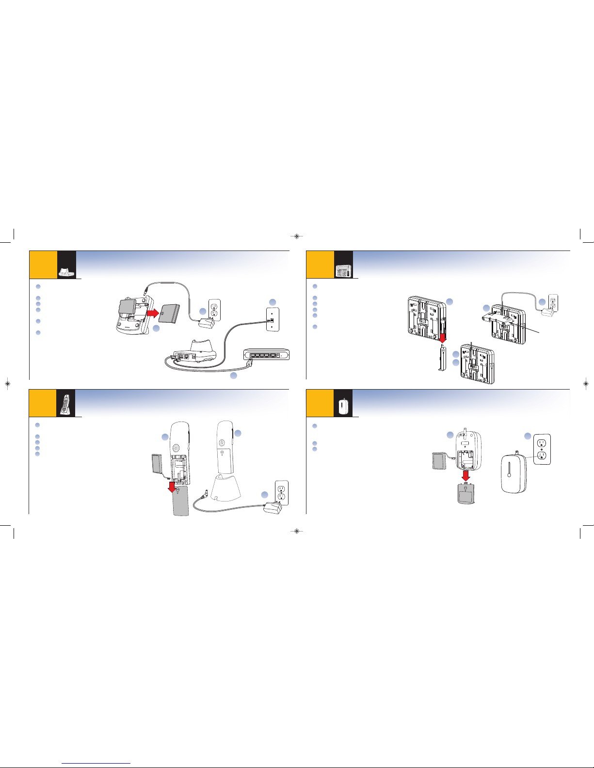
Connect Grid Extender (GX): Open Box #4
Extends the security coverage area
1
Connect Base: Open Box #1
Connects your LifeShield system to the Internet
2
Connect Handset: Open Box #2
Provides security and telephone control throughout the home
Locate Handset/Charger for easy access, perhaps next to your bed
Connect battery
Connect power cord
Place
Handset
in
Charger
Charge
Handset
for at least 30 minutes
before starting Step 5*
*NOTE:CHARGE BATTERY FOR 2 HOURS PRIOR TO MAKING PHONE CALLS.
3
C
A
N
C
E
L
/
O
FF
I
N
S
T
A
N
T
S
T
A
Y
C
H
I
M
E
A
W
A
Y
P
A
N
I
C
T
A
L
K
E
N
D
M
U
T
E
P
A
G
E
2
A
B
C
3
D
E
F
1
4
G
H
I
5
J
K
L
6
M
N
O
7
P
Q
R
S
8
T
U
V
9
W
X
Y
Z
0
*
O
P
E
R
#
Connect Console: Open Box #3
Controls security and telephone functions
A
B
C
D
E
Locate
Grid Extender
in different room than
Console
and
Base
for maximum wireless coverage, ideally on interior wall*
Connect battery
Plug
Grid Extender
into wall outlet
B
C
C
B
F
E
D
C
B
D
Console Back View
Table Stand
I M PO RTA NT : F OL L O W S T E P S IN EX AC T O RD E R . DO NO T S KI P A HE AD .
OPTIONAL ACCESSORY: INCLUDED IN HOME KIT
A
B
C
D
E
F
A
B
C
*NOTE: PLACEMENT OF THE GRID EXTENDER IS MORE FLEXIBLE THAN THE BASE
OR CONSOLE. PLACE GRID EXTENDER TO EXPAND COVERAGE FOR SENSORS.
Locate
Base
near Modem/Router
Connect battery
Connect power cord
Connect white Internet Cable from
Base
to Modem/Router
Connect a phone cord from the
Base
to the phone wall jack*
If the phone wall jack is currently
being used, install a 2-1 phone
splitter/adapter
A
B
C
D
B
E
D
C
Phone Cord
Base Underside
Internet Cable
Modem/Router
E
F
*NOTE: IF PHONE WALL JACK IS NOT AVAILABLE NEAR BASE LOCATION,
YOU CAN CONNECT A PHONE LINE TO THE CONSOLE OR GRID EXTENDER.
_LifeShield-QSG-NONDSL.qxp:Layout 1 2/11/10 9:52 PM Page 4
Page 4
Closed Door
Open Door
Sensors
and
Magnets
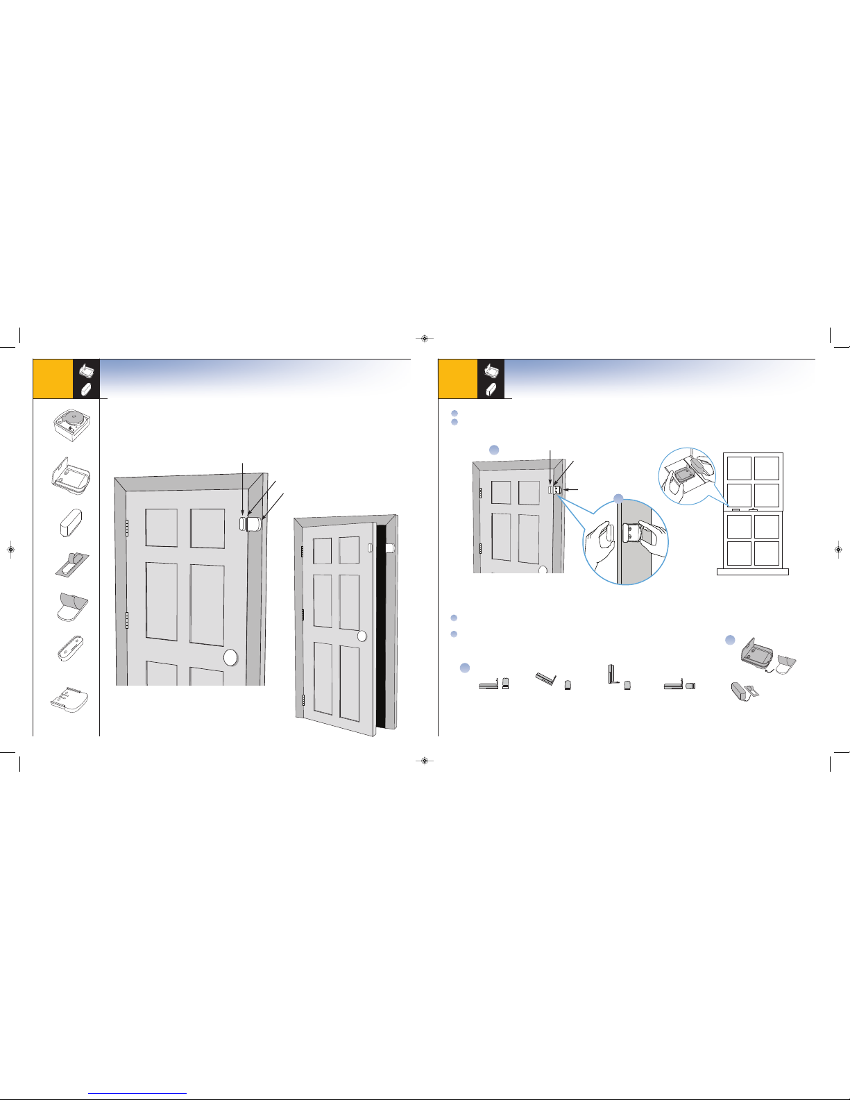
create security for doors and windows.
• When a door or window is closed, the
Sensor
and
Magnet
must be within 3/4” of each other
• As a door or window is opened the
Sensor
and
Magnet
separate causing the
Sensor
to chime or alarm
5
Sensors
IMPO RTANT: D O NOT ASSE MBLE ANY PIECE S FR OM SE NSOR BOX UNTIL INS TRUCT ED
Sensor
Bracket Tape
Bracket
Magnet
Magnet Tape
Magnet Spacer
(optional use)
Bracket Spacer
(optional use)
S E N S O R K I T C O N T E N T S
3/4” spacing
Sensor
Magnet
Select door or window that you want to monitor
With
Bracket
and
Magnet
in hand, select a location on the door or window for mounting
A
B
A
*NOTE:WHEN POSSIBLE, PLACE THE BRACKET ON THE STATIONARY FRAME OF DOOR OR WINDOW, AND PLACE THE MAGNET ON THE DOOR OR WINDOW ITSELF.
Bracket
Magnet
Double-Hung Window
Door Mounting
Window Mounting
3/4” spacing
Figure 1*.
Level Orientation
Figure 2.
Angled Orientation
Figure 3.
Perpendicular Orientation
Bracket
Magnet
D
Figure 4.
Perpendicular Orientation
*NOTE:SPACERS IN SENSOR BOX MAY BE USED ON THE BRACKET OR MAGNET TO ADJUST ALIGNMENT. SEE USER MANUAL FOR SPACER MOUNTING INSTRUCTIONS.
C
Various orientations between the
Bracket
and
Magnet
may be used as long as 3/4”
distance is not exceeded. See Example in Figures 1-4
Once you have determined the appropriate location and orientation for the
Bracket
and
Magnet
, attach them with double-sided tape
C
D
Mount Bracket & Magnet
Open Sensor box found inside "Sensor & Accessory" box
5a
B
_LifeShield-QSG-NONDSL.qxp:Layout 1 2/11/10 9:52 PM Page 6
Page 5
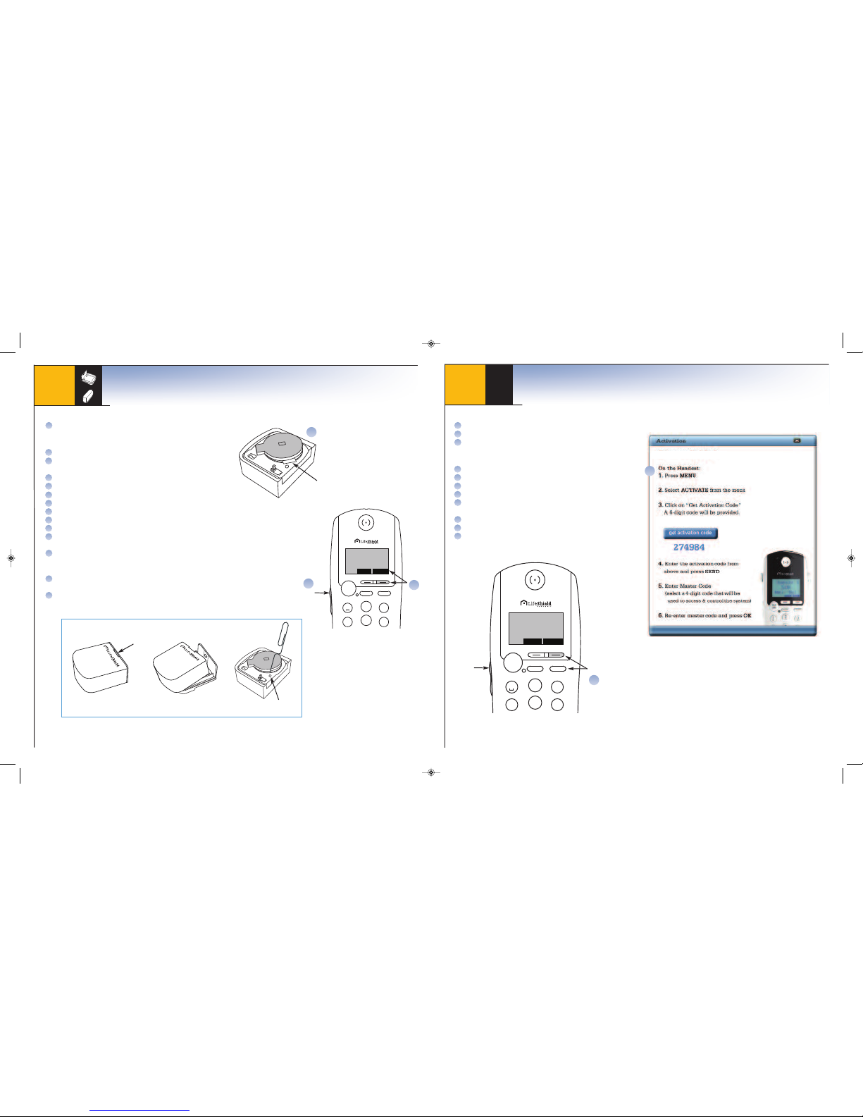
Using PC:
Go to
www.LifeShield.com
Enter
User Name
and
Password
Click on “
Get Activation Code
” and a 6-digit code will be provided
Using
Handset
:
Press MENU
On
Activate
, press SELECT
Enter
Activation Code
and press SEND
Upon activation acceptance press OK
Enter
Master Code
(Select a new 4-digit
code used to access and control the system)
Re-enter
Master Code
to confirm
Now testing communication to Central Monitoring*
Upon completion press OK*
1
2
3
4
5
6
ABC
DEF
GHI
JKL
MNO
TALK
END
MUTE SPKR
R ea dy to A rm
T h u 2/ 8 11 : 48a
PHNBK
MENU
Ca ll s: 2 M s g: 2
Activate Your System
6
D
Menu
Scroll
Button
A
B
C
H
D
E
F
G
J
K
I
1
2
3
4
5
6
A
BC
DEF
GHI
JKL
M
NO
TALK
END
MUTE SPKR
Not Ac ti va te d
PHNBK
MENU
Cal ls : 2 M sg :2
A
A
Scroll
Button
B
Menu
C
Battery Tab
For this install step you will need your
Handset
and
Sensor
:
Remove battery tab
Using
Handset
:
Press MENU
Scroll to
Security Setup
, press SELECT
(Scroll Button found on left side of
Handset
)
Enter default
Master Code 1234
Scroll to
Sensors
, press SELECT
On
<Add New>
, press SELECT
Scroll to desired
Sensor Type
, press SELECT
Wait 5 seconds
Clip
Sensor
into mounted
Bracket
(Display indicates you have 30 seconds)
Handset
display will indicate the
Sensor
is found and then added, press OK*
Edit
Sensor
name by pressing DELETE and type new name
using keypad, then press OK (Or edit name on web later)
On
Sensor
only, press SELECT
Testing your
Sensor
:
Test your
Sensor
by opening the door. Correct installation will
generate a chime. Otherwise, see troubleshooting in User Manual
Repeat Step 5 for additional
Sensors
*NOTE: IF THE SYSTEM DID NOT FIND THE SENSOR, REFER TO SENSOR RESET INSTRUCTIONS, THEN REPEAT STEPS ABOVE.
NOTE:
DISCONNECT BY SEPARATING SENSOR FROM BRACKET USING SLOT. RESET SENSOR BY
INSERTING PAPER CLIP INTO RESET HOLE.
SENSOR RESET INSTRUCTIONS
B
C
D
E
F
G
H
I
J
K
L
M
N
Place & Program Sensor
IMPO RTANT: I F YOU HAVE CLIP PED S ENSOR INTO BRAC KET, P LEASE SEE SENS OR RE SET BOX.
5b
Reset Hole
Slot
NOTE: IF YOU DO NOT SUBSCRIBE TO PHONE SERVICE, YOUR SYSTEM MAY EXHIBIT A TROUBLE BEEP.
GO TO LIFESHIELD.COMAND CLICK SECURITY/SYSTEM SETTINGS/EDIT AND SELECT 'NO'
ADJACENT TO THE HOME PHONE LINE FIELD TO CLEAR THE TROUBLE.
NOTE: LOW BATTERIES MAY CAUSE A TROUBLE BEEP UPON ACTIVATION. TO CANCEL TROUBLE BEEP
AND ALLOW TIME FOR CHARGING, PRESS CANCEL/OFF KEY, THEN PRESS OK ON DISPLAY.
C
Your system is now operational. If you are professionally monitored, for the next seven days
it will be in a non-monitored “Practice” mode to allow you to become fully acquainted with
all of its features. For help, call Customer Support at 1.877.XXX XXXX.
*NOTE: IF YOU DO NOT SUBSCRIBE TO PROFESSIONAL MONITORING SERVICE
STEPS J AND K DO NOT APPLY.
Welcome to LIFESHIELD
_LifeShield-QSG-NONDSL.qxp:Layout 1 2/11/10 9:52 PM Page 8
Page 6
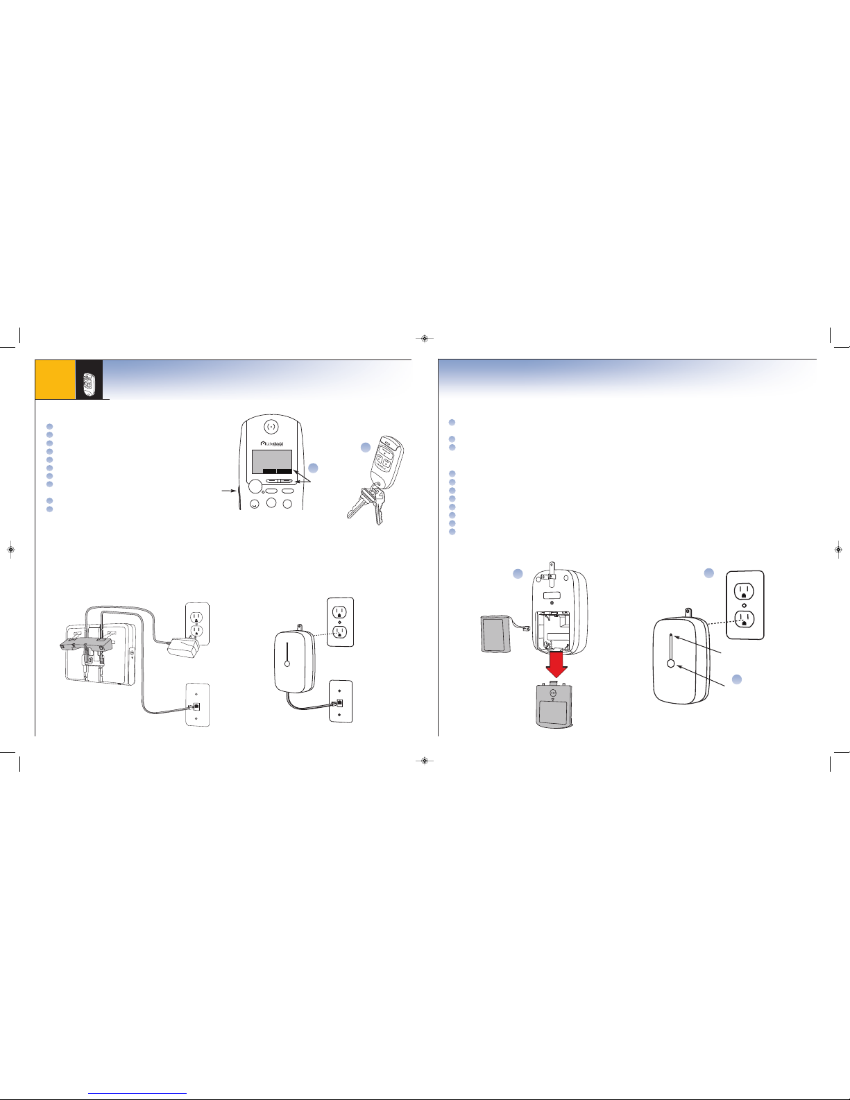
Additional Considerations
Add Additional Grid Extender (GX): (Open additional Grid Extender box)
Locate
Grid Extender
in different room from
Console, Base
and previously installed
Grid Extender
for maximum wireless coverage
Connect battery
Plug
Grid Extender
into wall outlet
Using
Handset
:
Press MENU
Scroll to
Security Setup
, press SELECT
Enter your
Master Code
Scroll to
GCs
or
Handsets
, press SELECT
On
<Add New>
, press SELECT
Press and hold center button on
Grid Extender
until LED flashes rapidly
Handset
display will indicate GXfound, press OK
Edit
GX
name, then press OK (or edit name on web later)
B
C
Center Button
LED
I
A
B
D
E
F
G
H
I
J
K
For this install step you will need your
Handset
:
Press MENU
Scroll to
Security Setup
, press SELECT
Enter
Master Code
Scroll to
Keychains
, press SELECT
On
<Add New>
, press SELECT
Wait 5 seconds
Press all buttons on
Keychain Remote
at same time
Handset
display will indicate the
Keychain Remote
is found and then added, press OK
On
Master User
, press SELECT
Scroll to Enable or
Not Enable
, press SELECT
(Makes Panic operable or inoperable on
Keychain Remote
)
7
A
B
C
D
E
F
G
H
G
OPTIONAL ACCESSORY: INCLUDED IN HOME KIT
A
Add Keychain Remote
Open Keychain Remote box found inside "Sensor & Accessory" box
1
2
3
ABC
DEF
TALK
END
MUTE SPKR
Re a dy t o Ar m
T hu 2 /8 1 1 :4 8a
PHNBK
MENU
Cal ls :2 M sg :2
Menu
Scroll
Button
I
J
C
If you have a phone wall jack near your
Grid Extender
or
Console
, a phone cord can be added to each for additional phone backup.
Add Phone Line Backup
Additional Considerations
_LifeShield-QSG-NONDSL.qxp:Layout 1 2/11/10 9:52 PM Page 10
Page 7
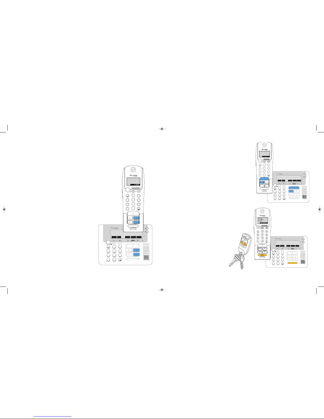
EVERYDAY A RMING SCE NARIOS:
STAYING HOM E DURING THE DAY – STAY ARMI NG
Arm the system using the STAY key. A silent Exit Delay and an audible
Entry Delay is provided. Stay arming is great for anytime usage,
especially during the day when family members may be coming
and going from your home.
ARM
1. Press STAY on your
Handset
or
Console
2. Enter your
User Code
3. System is armed when the silent Exit Delay has expired
LEAVING YOUR HOME – AWAY ARMING
Arm the system using the AWAY key. It will provide an audible Exit
Delay. The Exit Delay beep will increase in frequency during the last
10 seconds of arming. Away arming is best used when you are leaving
your home unoccupied.
ARM
1. Press AWAY on your
Handset
or
Console
2. Enter your
User Code
3. System is armed when the Exit Delay has expired
CANCEL/OFF
INSTANT
STAY
CHIME
AWAY
PANIC
TALK
END
MUTE
PAGE
2
ABC
3
D
EF
1
4
GHI
5
JKL
6
MNO
7
PQRS
8
TUV
9
WXYZ
0
*
OPER
#
CANCEL/OFF
INSTANT
STAY
CHIME
AWAY
PANIC
TALK
END
MUTE
PAGE
2
ABC
3
DEF
1
4
GHI
5
JKL
6
MNO
7
PQRS
8
TUV
9
WXYZ
0
*
OPER
#
Using Your Lif eShield H ome Secur ity Syste m
Now that you have installed and activated your system, take the opportunity to learn how it can best fit your lifestyle.
We recommend that you try Arming, Disarming, Alarming and Panicking the system. For systems that are
professionally monitored this should be done during the "Practice" time.
STAYING HOM E FOR TH E EVENING – INSTANT ARMING
Arm the system using the INSTANT key. No Exit or Entry Delay
is provided with Instant arming. Instant arming is best used when
all family members are in for the evening and no entries or exits
from the home are expected. Opening a door when armed Instant
will generate an alarm immediately.
ARM
1. Press INSTANT on your
Handset
or
Console
2. Enter your
User Code
DISARM ING YOUR SYSTEM
DISARM
1. Press CANCEL/OFF on your
Handset
or
Console
2. Enter your
User Code
NOTE: To cancel an alarm follow the above disarm instructions.
PANIC AL ARM
For systems that are professionally monitored at the touch of the
Panic Key, help is available. Emergency personnel are dispatched
immediately. For systems that are self monitored, the Panic Key
will sound a local alarm only.
ALARM
1. Press and hold PANIC for 2 seconds
2. Select Police, Medical or Fire (Professionally
Monitored Only - If no selection is made,
Police will be dispatched)
On the
Keychain Remote
press STAY and AWAY at the same
time when near your home and the alarm will sound.
For professionally monitored systems the Police will be
dispatched immediately.
CANCEL/OFF
INSTANT
S
TAY
C
HIME
AWAY
PANIC
TALK
END
MUTE
PAGE
2
ABC
3
DEF
1
4
GHI
5
JKL
6
MNO
7
P
QRS
8
TUV
9
WXYZ
0
*
OPER
#
1
2
3
4
5
6
7
8
9
0
*
ABC
D
EF
GHI
JKL
MNO
PQRS
TUV
WXYZ
O
PER
#
INSTANT
STAY
CHIME
AWAY
PANIC
T
ALK
END
MUTE SPKR
C
ANCEL/OFF
Ready to Arm
Thu 2/8 11:48a
PHNBK
MENU
Calls:2 Msg:2
INSTANT
STAY
AWAY
PHNBK MENU CONNCT WEATHR ALERTS
Ready to Arm
Thu 2/8 11:48a
Calls: 0 Msg:0
PHNBK MENU CONNCT WEATHR ALERTS
Ready to Arm
T
hu 2/8 11:48a
C
alls: 0 Msg:0
BACK CONNCT WEATHR ALERTS
Press 1: Police
Press 2: Medical
Press 3: Fire
SELECT
1
2
3
4
5
6
7
8
9
0
*
ABC
DEF
GHI
JKL
MNO
PQRS
TUV
WXYZ
OPER
#
CANCEL/OFF
INSTANT
STAY
CHIME
AWAY
PANIC
TALK
END
MUTE SPKR
Ready to Arm
Thu 2/8 11:48a
PHNBK
Calls:2 Msg:2
INSTANT
STAY
AWAY
Warning! For professionally monitored systems,
Central Monitoring will not call to verify a Panic
alarm before dispatching.
_LifeShield-QSG-NONDSL.qxp:Layout 1 2/11/10 9:52 PM Page 12
Page 8
For help, call Customer Support at
1.877.XXX XXXX
Beware!! When arming remotely, either through
www.
LifeShield.com
or dial-in,
the system will arm immediately with no exit delay.
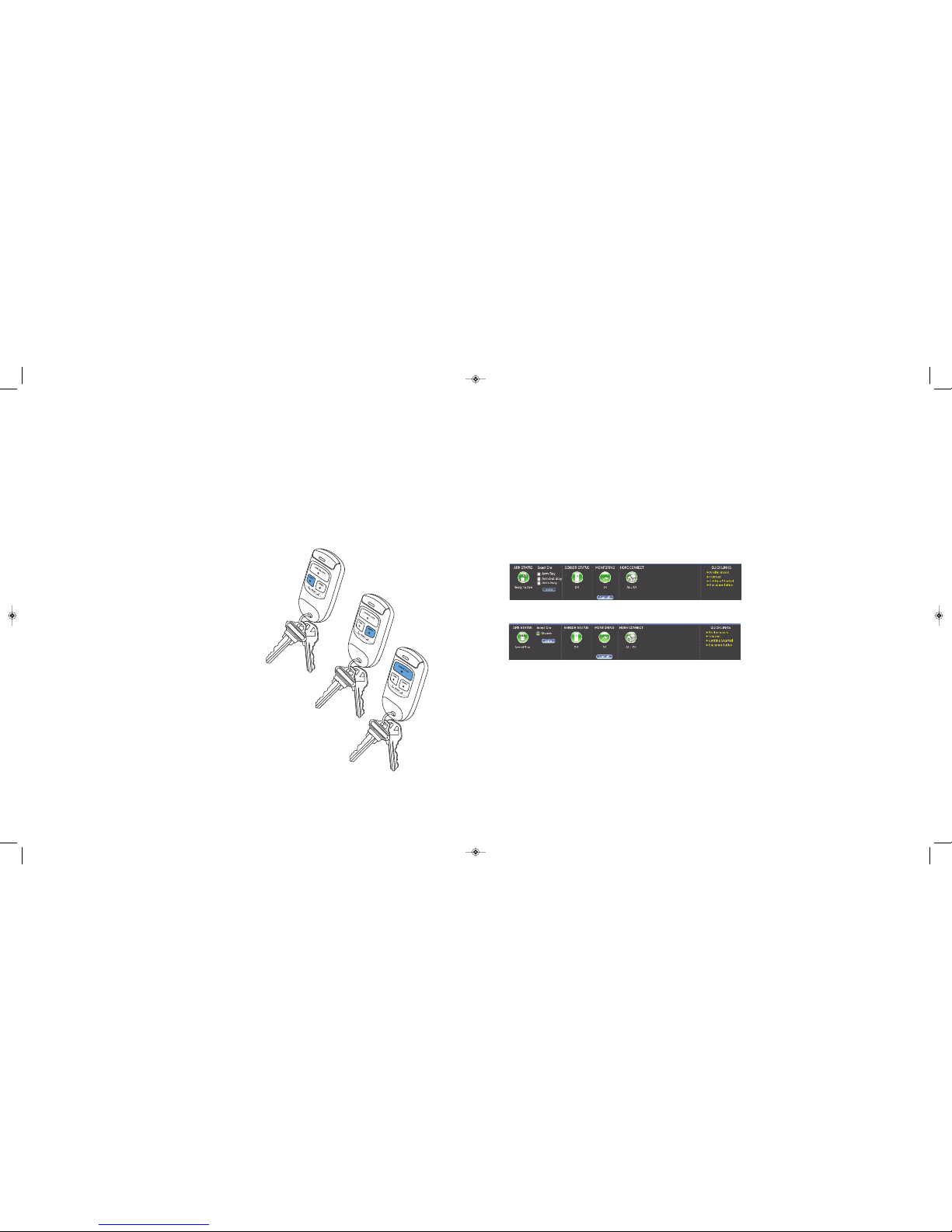
REMOTE ARMING/DI SARMING O F YOUR SY STEM
There are many ways to remotely arm or disarm your system.
•
Keychain Remote
- from the exterior of your home
•
Remote Dial-In
- from any touch-tone phone, anywhere in the world
•
LifeShield.com
- from a computer with broadband Internet access
KEYCHA IN REMOTE
Disarm your system before you enter your home or arm your system as you close the door behind you using
your
Keychain Remote
. It works from within 15 feet from your door, and does not require a User Code.
ARM
1. Press STAY or AWAY on Keychain Remote
2. The system will respond with a light blink and beep, letting you know
the system is armed
DISARM
1. Press OFF to disarm the system before entering
2. The system will respond with a light blink and beep, letting you know
the system is disarmed
REMOTE DIAL-IN
From anywhere, on any touch-tone phone, remotely arm or
disarm your system.
ARM/DIS ARM
1. Dial your home phone number
2. When answered by system, press star
*
3. Enter
User Code
4. Press 9for security system access
a
. To
Arm St ay
, select 1
b
. To
Arm Aw ay
, select 2
c
. To
Disarm
, select 4
LIFESHIELD.COM
From a PC that has broadband Internet access you can go to
LifeShield.com
, anywhere and anytime,
and arm or disarm your system.
ARM
1. Login to
LifeShield.com
2. Enter
User Name
and
Password
3. Click
Arm Stay
or
Arm Away
or
Arm Inst Stay
4. Click
Enter
DISARM
1. Click
Enter
_LifeShield-QSG-NONDSL.qxp:Layout 1 2/11/10 9:52 PM Page 14
Page 9
© 2010 LifeShield, Inc. All rights reserved. LifeShield logo is a registered trademark and LifeShield Home Security is a trademark of LifeShield Services,
LLC.
_LifeShield-QSG-NONDSL.qxp:Layout 1 2/11/10 9:52 PM Page 16
 Loading...