

Page 1

User Codes
Creating User Codes via www.LifeShield.com
1. Go to www.LifeShield.com
2. Enter your User Name and Password
3. Navigate to Settings tab, then to User Codes
4. Click Add
5. Fill in the requested fields
6. Click Continue
7. Click Submit Changes when requested
Figure 37. LifeShield - User Code Screen
To Delete a Keychain Remote from a User via www.LifeShield.com:
(Figure 37)
(Figure 38)
(Figures 37 and 38):
Figure 38. LifeShield - Create/Edit User Code Screen
1. Go to www.LifeShield.com
2. Enter your User Name and Password
3. Navigate to Settings tab, then to User Codes
4. Edit on the same line as the user
5. Adjacent to Keychain Remote field, click Remove Keychain
6. Click Continue
7. Click Submit Changes when requested
[www.LifeShield.com]
(Figure 37)
(Figure 38)
USING YOUR SECURITY SYSTEM
[60]
Page 2

Suppressing Trouble Sounds
The system provides Trouble Sounds to alert the user that it requires attention. Trouble Sounds can be generated as a result of
t
You can only suppress Trouble
Sounds when the system is disarmed.
If you suppress Trouble Sounds
after a first trouble condition, and
then a second trouble condition
occurs, Trouble Sounds will start
again. This might happen, for example, if you lose AC power, and
then lose Internet a few minutes
later.
a low battery, the loss of Internet or phone connection, etc. You can limit the hours during the day when Trouble Sounds are
sounded and you can temporarily suppress the sounds until you can address the trouble condition.
Suppressing Trouble Sounds (Handset/Console)
To suppress a Trouble Sound while it is occurring, on a Handset or Console :
1. Press CANCEL/OFF
2. Press OK
You can control the length of time that Trouble Sounds are suppressed (when you press CANCEL/OFF), on a Handset or Console:
1. Press MENU
2. Scroll to Security Setup, press SELECT
3. Enter your Master Code
4. Scroll to Suppress Trouble, press SELECT
5. Scroll to the desired setting (The settings range from 0 to 48 hours. Factory default is 24 hours.)
Setting the Time of Day when Trouble Sounds are Disabled (via www.LifeShield.com)
You can control the hours of the day when Trouble Sounds are disabled/silenced, such as while you are sleeping. Some conditions, like No Internet or No AC are brief and corrected quickly by the utility and you may not want to be awakened. Note that
there must be at least 1 hour per day when Trouble Sounds are not silenced. (Figure 39):
[61]
1. Go to www.LifeShield.com
2. Enter your User Name and Password
3. Click Settings
4. Navigate to System Settings
5. Click Edit
6. Select desired Trouble Silence Start and End Time
7. Click Continue
8. Click Submit when requested
USING YOUR SECURITY SYSTEM
Figure 39. LifeShield - Edit System Settings Screen
[www.LifeShield.com]
Page 3

Event Log/Network Configuration
Alarm Event Log (Handset/Console)
For Alarm Monitoring subscribers the system will log all messages (in an Event Log) sent to the Alarm Monitoring Center.
This is separate from the entire Recent Event log on www.LifeShield.com. These messages can be viewed from your Handset
or Console
1. Press MENU
2. Scroll to Security Setup, press SELECT
3. Enter your Master Code
4. Scroll to Event Log, press SELECT
Network Configurations
Your LifeShield system usually connects to your Internet (broadband) network automatically using the same DHCP protocol as
your PC or laptop. However, some networks use Static IP Addresses. If you are not familiar with Static IP Address, it is likely that
your network does not have this requirement. If you do require a Static IP Address, complete this setup process from either your
Handset or Console:
1. Press MENU
2. Scroll to Security Setup, press SELECT
3. Scroll to Network Mode, press SELECT
4. Scroll to Address Type, press SELECT
5. SELECT Static, press OK
6. SELECT View/Edit
7. Enter the following information and press OK as you complete each step:
:
IP Address
Gateway
SubnetMsk
PrimDNS
Second DNS
MAC Address
i
You can receive notifications on
your email, mobile device, and/or
Home Alert for any event in your
system. Set these up at
www.LifeShield.com, Security tab,
Recent Events window,
notification setup button.
Power Outage
Your LifeShield Home Security system operates on AC power and battery backup. In the event that both AC and battery
power is lost while the system is armed, your system will automatically return to the armed state when the power is restored.
After a complete AC and battery outage, the system will wait 1 minute before responding to Sensor activity once power is restored.
[www.LifeShield.com]
USING YOUR SECURITY SYSTEM
[62]
Page 4

Home Connect
The Home Connect feature gives you access to view and control another LifeShield Home Security system if the owner of that system gave you proper
permission. Example uses include an elderly parent who has special needs or a neighbor that is going on vacation.
This same feature allows you to invite someone to look in on your system. The LifeShield Home Connect feature offers 2 levels of access as shown in Table 3:
Access Level Description
Alarm Only
Full Control
Table 3: Home Connect Access Levels
Inviting a Home Connect Participant
Receive Alarm and System Notifications from the connected home’s system directly to your home as a Home Alert
on LifeShield.com or via email.
In addition to Alarm Only access, the connected home can be Armed and Disarmed from your system Handset,
Console or LifeShield.com.
To give a trusted friend or family member permission to access your system:
1. Go to www.LifeShield.com
2. Enter your User Name and Password
3. Click on Home Connect tab
4. Click on Invite Someone Now
5. Enter requested information
6. Click Submit
(Figures 40 and 41)
(Figure 41)
Figure 40. LifeShield - Home Connect Tab
Once the participant has accepted your invitation, you will receive notice on the Invite Sent window. They will then be able to access your system.
[63]
USING YOUR SECURITY SYSTEM
Figure 41. LifeShield - Home Connect Invite
[www.LifeShield.com]
(Figure 42)
Page 5

Accepting a Home Connect Invitation
If you receive a Home Connect email invitation from someone:
1. Go to www.LifeShield.com
2. Enter your User Name and Password
3. Click on Home Connect tab
4. Navigate to the Accept An Invite panel
5. Enter invitation code that is provided in the Home Connect email you received from the requester
6. Click Accept Invite
Home Connect
Accessing and Controlling a Home Connect System via the Handset/Console
1. Press CONNCT on your Console, or press MENU, then scroll to Home Connect on your Handset, press SELECT
2. Enter your own User Code
3. Select the system to which you want to connect (if there is more than one)
4. The display will show the status of the remote system to which you are Home Connected
5. The ARM and DISARM keys on your Handset and Console will control the remote system to which you are Home Connected
:
Figure 42. LifeShield - Home Connect Invitation Acceptance
[www.LifeShield.com]
USING YOUR SECURITY SYSTEM
[64]
Page 6

Notifications
i
As the limit for Home Alerts is
exceeded, the system
automatically deletes the
oldest Alert.
You will be notified of a new
Home Alert message by an audio
tone and a message on your
Handset or Console. The blue
LED will flash as well.
The Home Alert Messages
light remains lit until you have
viewed the message. Messages
are time stamped with the most
recent message displayed first.
The system stores the most
recent 20 messages.
Your LifeShield Home Security system can send you notifications about events that happen in your home. These
notifications can be received via email, mobile device, and/or Home Alert. You can read Home Alert messages via your Handset,
Console or LifeShield.com. In addition to events from your home, such as Sensor openings, you can also receive severe
weather alerts and reminders.
Notification Setup (www.LifeShield.com)
Notification setup is accessed from the Security tab, Recent Events window, on www.LifeShield.com.
(Figures 43 and 44)
[65]
Figure 43. LifeShield - Security Tab Notification Setup
USING YOUR SECURITY SYSTEM
Figure 44. LifeShield - Event Notification Setup
[www.LifeShield.com]
Page 7

To setup a Notification to send messages to your email, mobile device or Home Alert (Figures 45 and 46):
1. Go to www.LifeShield.com
2. Enter your User Name and Password
3. On Security tab, navigate to Recent Events
4. Click Notification Setup
5. Click Add New
6. Select System Event and enter descriptive notification Name
7. Pull down event Type (Alarm, Arm/Disarm, Sensor Open/Closed, Trouble, etc.)
8. Example Alarm Type:
a. Pull down desired event Detail (i.e. All, Burglary, Fire, Panic, Burglary Panic, Fire Panic, Medical Panic)
b. Pull down event Occurrence (i.e. Does Occur, Does Not Occur)
9. Click Always send a notification when this event occurs; or
10. Click Customize event notification period (for events that happen only at certain times)
11. Select All Day (for events that happen anytime during day); or
12. Pull down Start Time and End Time (for events in certain time windows)
13. Click desired Event Day(s) or click All Days
14. Click desired Notification Address(es) or
15. Click Manage Addresses to add additional addresses (up to 4 total plus Home Alert)
16. Click Submit
Notifications
Figure 45. LifeShield - Alarm Notification Example
[www.LifeShield.com]
USING YOUR SECURITY SYSTEM
[66]
Page 8

Notifications
Editing or Removing a Notification
You can edit or remove an existing notification by selecting Edit or Remove
adjacent to the notification you want to modify.
Activate/Deactivate a Notification
You can activate or deactivate an existing notification by clicking on the Active
check box adjacent to the desired notification.
Home Alert In-Box
Home Alerts are notifications of system events, reminders or weather alerts
that are sent to your home. They can be retrieved from your in-home
equipment or from your LifeShield.com Home Alert In-Box on the Security
tab. When setting up notifications, you will be able to select a Home Alert as
an address location.
(Refer to Figure 47)
Active
Check
Box
Figure 46. LifeShield - Event Notification Setup
[67]
USING YOUR SECURITY SYSTEM
Figure 47. LifeShield - Home Alert
[www.LifeShield.com]
Page 9

Home Alerts/Weather Updates
Retrieving Home Alerts (Handset/Console)
To retrieve a Home Alert follow these steps:
1. From your Console, press ALERTS, or
2. From your Handset, press MENU
3. Scroll to Home Alert, press SELECT
4. Press DELETE to delete a message or NEXT to
keep the message and view the next alert
Retrieving Home Alerts (LifeShield.com)
Weather
Home Alert
Home Connect
BACK SELECT
3/27 5/17
Burglary Alarm
Door
DELETE NEXT
To retrieve your Home Alert messages follow these steps:
1. Go to www.LifeShield.com
2. Enter your User Name and Password
3. Navigate to the Home Alert panel
4. Use scroll bar to see your Home Alert messages
Weather Updates
Your LifeShield Home Security system provides a convenient way to obtain your local 3-day weather forecast through your
Console or Handset. The forecast is localized to your monitoring zip code.
To view Weather Updates follow these steps:
Handset:
1. Press MENU
2. Scroll to Weather, press SELECT
3. To view the next day’s weather forecast, press NEXT
i
Severe weather alerts are sent to
you as Home Alerts if turned on
from LifeShield.com.
The temperature format can be
changed from Fahrenheit to
Celsius by going to
www.LifeShield.com.
Console:
1. Press WEATHR
2. To view the next day’s weather forecast, press NEXT
[www.LifeShield.com]
USING YOUR SECURITY SYSTEM
[68]
Page 10

Using Your Telephone System
The Handset and Console are not only components of your LifeShield Home Security system, but also provide you with a full featured digital telephone
system. In this section you will find information on the following:
• Telephone system features
• Telephone system controls and functions
• Telephone system settings
• Phone Book features
• Answering system features
• Do not disturb
• Privacy
Note: If you don't subscribe to telephone services from a local provider, many of these features will either be inactive or not applicable.
[69]
USING YOUR TELEPHONE SYSTEM
[www.LifeShield.com]
Page 11

Controls and Functions
Console Telephone Controls and Features
Figures 48 and 49 highlight the telephone-specific functions located on both your Console and Handset.
89
1
7
6
5
4
3
2
Figure 48. Telephone Features on the Console
1. Scroll Button (Up/Down) – Navigates menus, adjusts volume, accesses recent calls
2. * - Pressing * in recent call list adds a 1 for long distance
3. # - Telephone answering system access (retrieving messages)
4. PAGE – Activates audible tone on Handsets for locating
5. MUTE – Mutes phone microphone
6. TALK/END – Initiates/ends calls and provides menu exit
7. Message LED – Indicates new message waiting
8. Soft Key – Changes functions based on menu navigation; active function shown on display above key; Main Display – PHNBK function retrieves
phone book entries
9. Soft Key – Changes functions based on menu navigation; active function shown on display above key; Main Display – MENU function allows menu
navigation
[www.LifeShield.com]
USING YOUR TELEPHONE SYSTEM
[70]
Page 12

Controls and Functions
Handset Phone Controls and Functions
11
1
10
9
8
7
6
2
3
5
Figure 49. Phone Features on the Handset
4
1. Headset Jack
2. Soft Key – Changes functions based on menu navigation; active function shown on display above key; Main Display – MENU function allows
menu navigation
3. SPKR – Activates speaker phone
4. # – Access to telephone answering system (retrieve messages)
5. * – Pressing * prior to redialing from recent call list adds a 1 for long distance
6. MUTE – Mutes call
7. Scroll Button (Up/Down) – Navigates menus, adjusts volume, accesses recent calls
8. Message LED – Indicates new message waiting
9. TALK/END – Initiates/ends calls and provides menu exit
10. Soft Key – Changes functions based on menu navigation; active function shown on display above key; Main Display – PHNBK function retrieves phone book
entries
11. Handset Earpiece
[71]
USING YOUR TELEPHONE SYSTEM
[www.LifeShield.com]
Page 13

Some of the key features of the LifeShield system:
• Built-in digital telephone system (VoIP compatible)
• Console with built-in speaker phone
• Digital cordless phone, with built in speaker phone
• Built-in phone book, with 99 memory locations
• Answering system with voice prompts
• Mute and hold functions
• Caller ID and Call Waiting capability
• Do not disturb and privacy functions
• 3-way conference calling
• Date and time display
• Multi-handset expandable
• Room monitor
• Intercom
• Remote intercom (via the answering system) from any touchtone phone
Telephone Displays
The LifeShield system displays telephone-related information on the third line of the display.
Telephone Operations
i
The various display messages are
outlined in Tables 8, 9 and 10.
The third line of the main menu display on your telephone provides you with the
number
Receiving Calls
You can receive calls from either the Handset or Console. The LifeShield system will display Ringing during an incoming call.
Selecting IGNORE on the Handset or Console will send an incoming call to the Answering System.
If Caller ID is provided by your utility, the caller’s information will be shown on the display. If Caller ID is unavailable or blocked,
the Caller information may display as Private or Unknown.
of messages (Msg) in your telephone’s answering system.
Ready to Arm
Thu 2/8 11:48a
Calls: 0 Msg:0
PHNBK MENU
Ready to Arm
Thu 2/8 11:48a
Ringing
IGNORE MENU
number
of calls received (Calls) and the
[www.LifeShield.com]
USING YOUR TELEPHONE SYSTEM
[72]
Page 14

Telephone Operations
i
If Auto Answer On is enabled,
when you pick up the Handset
from the Cradle, the call will be
active. Therefore, you
to press TALK/END or SPKR to
receive your call.
do not need
1. To Receive a Call Press TALK/END or SPKR
TALK
END
Figure 50. TALK/END on Handset
(Handset Only; Refer to Figure 50)
Placing Calls
You can make calls from either the Handset or Console.
To place a call:
1. Press TALK/END or SPKR (Handset only)
2. Key in number
or
1. Key in number
2. Press TALK/END or SPKR (Handset only)
Ready to Arm
Thu 2/8 11:48a
2153554555
.
[73]
CANCEL DELETE
3. When the call connects, begin speaking
4. Once the call begins, the display shows the duration of the call in real time
Ready to Arm
Thu 2/8 11:48a
Talk hh:mm:ss
HOLD FLASH
Ending Calls
To end a call:
1. Press TALK/END
USING YOUR TELEPHONE SYSTEM
[www.LifeShield.com]
Page 15

Telephone Operations
Flash and Call Waiting
If you subscribe to Call Waiting with your service provider, you can answer a 2nd incoming call while on a 1st call. If you have
Caller ID service, the waiting call’s information is displayed.
Ready to Arm
Incoming Caller’s Name
Incoming Caller’s Number
HOLD FLASH
To pick up a 2nd incoming call while you are already on a call:
1. Press FLASH
2. The original call will be put on hold and you can begin talking to the new caller
3. Press FLASH again and you will be reconnected to the original call
Placing a Call on Hold
While on a call, you can put the call on hold:
1. Press HOLD
2. Call on Hold will appear on the display
3. To return to the call press TALK/END
i
Pressing the HOLD soft key puts
new call on hold.
If a call is placed on hold for
longer than 5 minutes, it will be
automatically disconnected.
Ready to Arm
Thu 2/8 11:48a
Call On Hold
PHNBK MENU
Earpiece and Speaker Volume
While on a call, you can change the volume of the
Earpiece or Speaker by using the Scroll buttons on
the Handset or Console.
(Figure 51)
The display shows the Volume Level in bars.
Volume
Scroll
HOLD FLASH
[www.LifeShield.com]
Buttons
Figure 51. Scroll Buttons Location
USING YOUR TELEPHONE SYSTEM
Scroll Buttons
[74]
Page 16

Telephone Operations
Mute Microphone
While talking on a call, you can mute the Microphone by selecting the MUTE button on the Handset or Console:
1. Press MUTE
2. The display shows that the call is muted along with the running duration of the call
3. Press MUTE again to take the device off of mute
Paging
Both the Base and the Console have a Page button for locating a misplaced Handset.
To Page your Handset:
1. Press PAGE on Base or Console
2. All Handsets display Paging and beep for a maximum of 10 seconds
3. Press OK on Handset to stop paging
Paging
OK
Recent Calls
The LifeShield phone system saves 20 of your most recent incoming or outgoing calls for retrieval and redial from either your Handset or Console.
Viewing Recent Calls
To view a call from your recent call list:
1. Use scroll buttons until you reach the desired phone number
O Caller Number
06/07 5:12p
EXIT OPTION
Caller Name
I Caller Number
06/07 3:02p
EXIT OPTION
Each call in the list is labeled with an “I” for Incoming Call or “O” for Outgoing Call.
If you subscribe to Caller ID service or the caller information is already stored in your Phone Book, then the Caller ID information is shown on the display along
with the date and time of the call.
[75]
USING YOUR TELEPHONE SYSTEM
[www.LifeShield.com]
Page 17

Redialing Recent Calls
To redial a call from your recent call list using your Handset or Console follow these steps:
1. Use the scroll buttons until you reach the desired phone number you would like to redial
2. Press * to add a 1 pre-dial digit in front of your recent call number if required for long distance
3. Press TALK/END or SPKR on the Handset or press TALK/END on the Console to redial the number
Saving Recent Calls
You can
1. Use the scroll buttons to view recent calls
2. Stop at the number that you want to save to your Phone Book
3. Press OPTION
4. Scroll to Save, press SELECT
save calls
CallList Options
Save
Delete Entry
to your Phone Book from either the Handset or Console:
Telephone Operations
i
The steps for manually entering
numbers in your Phone Book are
outlined in the Phone Book
Operations section.
The steps for deleting incoming,
outgoing or all recent calls are
similar.
BACK SELECT
Deleting Recent Calls
You can delete a recent phone entry, delete all incoming calls, delete all outgoing calls or delete all calls from either the Handset or Console:
1. Use the scroll buttons to view recent calls and press OPTION on desired call
2. Scroll to Delete Entry, press SELECT
CallList Options
Save
Delete Entry
BACK SELECT
Out of Range
If you attempt to make a call when you are out of range, the Handset or Console will display Out of Range and sound an
out-of-range beep. This message will also appear if you walk out of range while on a call. You have 30 seconds to walk back
into range before you will lose the call.
[www.LifeShield.com]
USING YOUR TELEPHONE SYSTEM
[76]
Page 18
Telephone Operations
Telephone Settings
i
While the phone is ringing, you
can change the ring volume using
the Scroll Button on the
Handset or Console. The display
shows the Ringer Volume bar
level.
The Handset and Console phone settings can be changed on each device. These settings include:
• Ring Tones (10 to choose from)
• Ringer Volume
• Display Contrast
• Key Beeps
• Key Lock (telephone keys only)
• Auto Answer (from phone cradle)
Changing Phone Settings
To change any of the above listed settings follow these steps:
1. Press MENU
2. Scroll to Phone Setup, press SELECT
3. Scroll to Handset or Console (depending on the device being used, the menu will indicate Handset or Console),
press SELECT
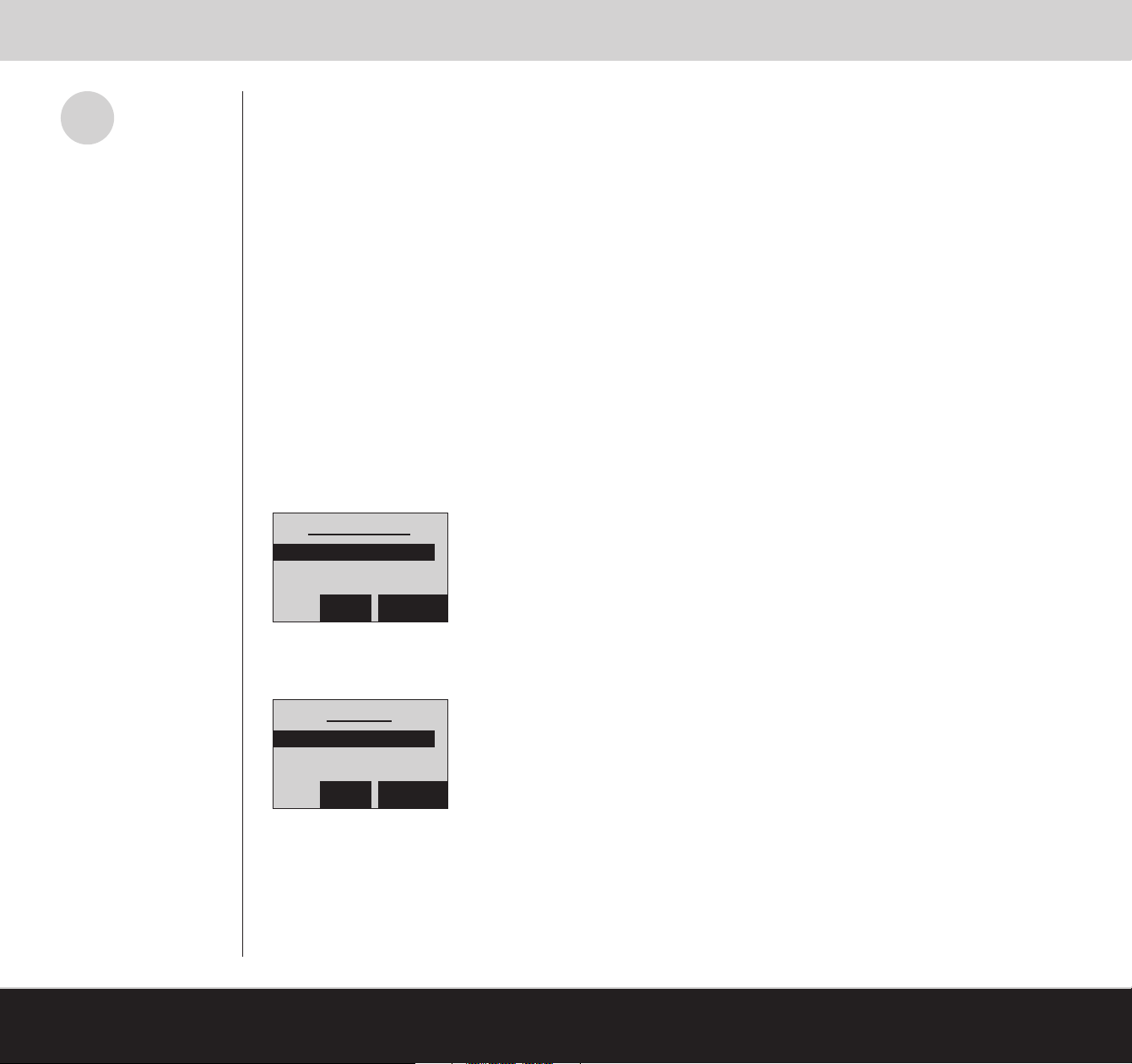
Phone Setup
Handset
Answer System
[77]
BACK SELECT
4. Scroll to the desired category that you want to change (i.e., ring tones, ringer volume, display contrast, key beeps, key lock
and auto answer), press SELECT
Handset
Ring Tones
Ringer Volume
BACK SELECT
5. Scroll to desired setting, press SELECT
USING YOUR TELEPHONE SYSTEM
[www.LifeShield.com]
Page 19
Phone Book Operations
The LifeShield Telephone system has built-in Phone Book support available from both the Handset and Console, and can
store up to 99 numbers. These entries can be a combination of manual entries and Caller ID inputs.
(Refer to Table 4)
i
Phone Book Features Description
Number of Entries The Phone Book can store up to 99 entries.
Multiple Entry Options
Distinctive Ring
Phone Book entries can be made manually or saved from the recent call list
with or without Caller ID information.
Selectable from a list of 10 predefined ring tones. Handsets and Console will not ring
until Caller ID can be verified and a distinctive ring applied.
Speed Dial You can assign the 1-9 number buttons to a particular Phone Book entry, which allows
that entry to be dialed when the assigned button is held down for 2 seconds.
Table 4: Phone Book Features
Adding a Phone Book Entry
You can add a Phone Book entry from the Handset or Console.
To add an entry to your Phone Book follow these steps:
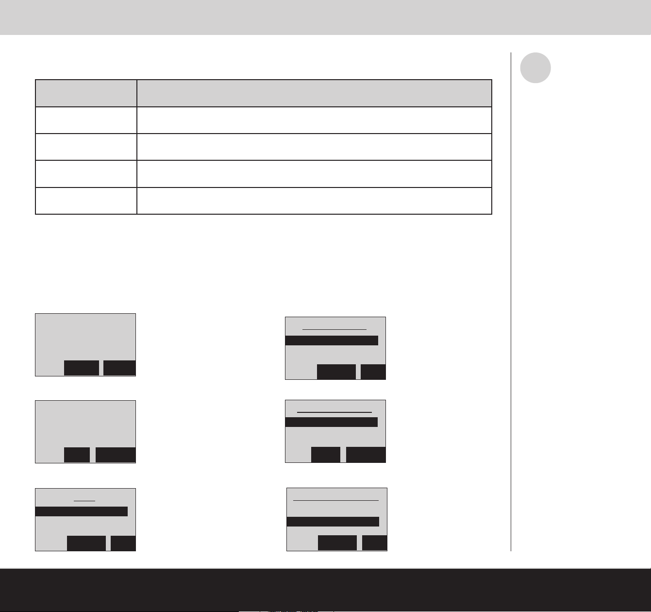
1. Press PHNBK
Ready to Arm
Thu 2/8 11:48a
Calls:0 Msg:0
PHNBK MENU
4. Enter Phone Number, then press OK
Phone Number
_
DELETE OK
The Phone Book supports
dialing, editing, deleting, adding
and saving entries.
2. On <Add New>, press SELECT
<Add New>
Name 1
Name 2
BACK SELECT
3. Enter Name using the alpha numeric keypad, then press OK
Name
_
DELETE OK
[www.LifeShield.com]
5. Scroll to desired speed dial location, press SELECT
Speed Dial Key
<None>
0 Key
BACK SELECT
6. Scroll to desired Distinctive Ring tone, press OK
Distinctive Ring
<Default>
Tone 1
DELETE OK
USING YOUR TELEPHONE SYSTEM
[78]
Page 20
Phone Book Operations
Viewing and Calling a Phone Book Entry
You can view your Phone Book entries from the display on the Handset and Console.
To view an entry in your Phone Book follow these steps:
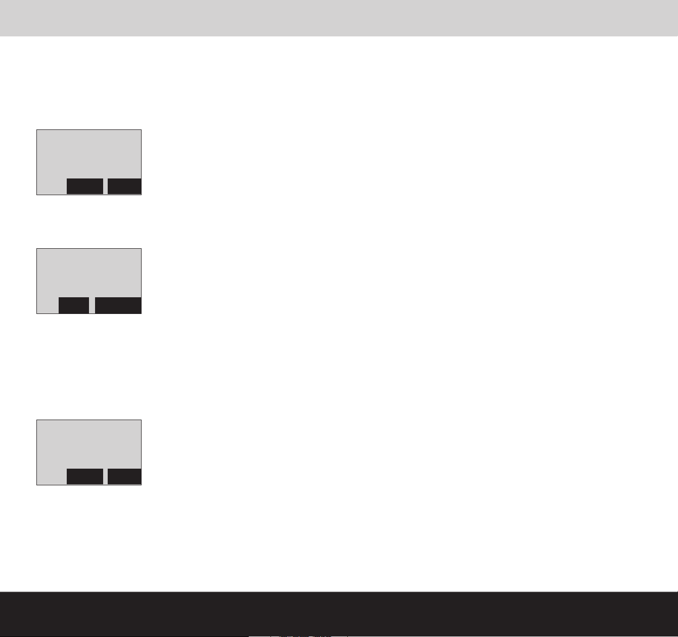
1. Press PHNBK
Ready to Arm
Thu 2/8 11:48a
Calls:0 Msg:0
PHNBK MENU
2. Scroll to desired entry in list, press SELECT or
3. Press the alpha numeric keys corresponding to the Phone Book name entry you desire. This will take you to your Phone Book entries starting with that key’s
corresponding letters. (Example: The corresponding letters associated with the number 2 on the keypad are A, B and C.)
Caller Name
Caller Number
SpD:- Rng:-
BACK OPTIONS
4. Press TALK/END or SPKR; the phone will begin dialing the selected number
Editing and Deleting a Phone Book Entry
You can edit or delete a Phone Book entry from the display on the Handset and Console.
To edit and delete a Phone Book entry follow these steps:
1. Press PHNBK
Ready to Arm
Thu 2/8 11:48a
Calls:0 Msg:0
PHNBK MENU
2. Scroll to desired entry in list, press SELECT or
3. Press the alpha numeric keys corresponding to the Phone Book name entry you desire. This will take you to your Phone Book entries starting with that key’s
corresponding letters. (Example: The corresponding letters associated with the number 2 on the keypad are A, B and C.)
[79]
USING YOUR TELEPHONE SYSTEM
[www.LifeShield.com]
Page 21
Phone Book Operations
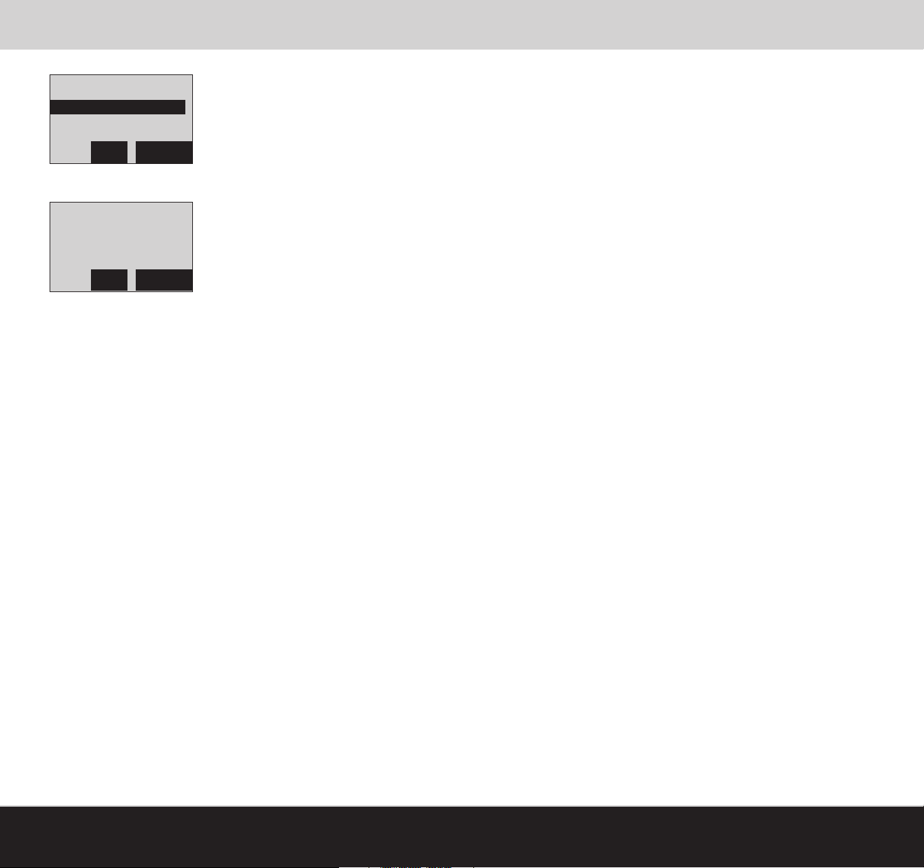
<Add New>
Name 1
Name 2
BACK SELECT
A Summary View of the Phone Book is displayed.
Caller Name
Caller Number
SpD:1 Rng:1
BACK SELECT
4. Press OPTIONS
5. Scroll to Edit or Delete and press SELECT
Speed Dial
For currently assigned Speed Dial buttons, the assigned name will be listed for that button. You can select an unused button and reassign that button to the
Phone Book entry currently being edited.
Distinctive Ring
Your system provides you with 10 distinctive tones which you can assign to Phone Book entries. <Default> is the default setting which has assigned your existing standard ring tone.
[www.LifeShield.com]
USING YOUR TELEPHONE SYSTEM
[80]
Page 22
Answering System Operation
The LifeShield system includes a built-in, full-featured telephone answering system. You can customize and operate the system
t
Notifications of new messages
are displayed on the third line of
the Handset or Console main
display and by the blinking blue
light next to the TALK/END key.
i
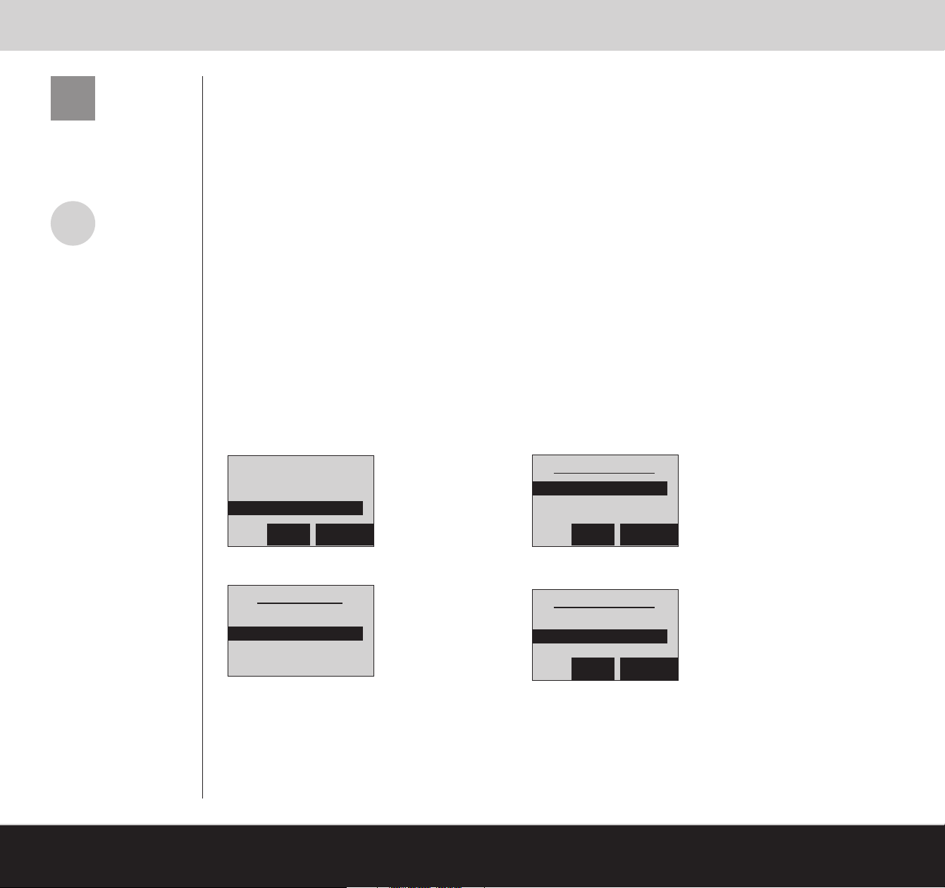
The factory default for the Answering System is OFF .
through the Handset, Console or remotely from another telephone.
The features of the answering system are listed below:
• Digital Recording (no tape)
• Up to 12 Minutes of Recording Time
• Call Screening
• Personal or Prerecorded Greetings
• Time and Day Announcement
• Remote Message Retrieval
• Toll Saver
• Message Alerts
• At Home Retrieval of Messages by any LifeShield Telephone
Enable Answering System
The Answering System can be enabled from either the Answering System Settings or Answering System Operating
Menu.
To enable Answering System from the Answering System Settings:
1. Press MENU
2. Scroll to Phone Setup, press SELECT
4. Scroll to Answer Enable, press SELECT
[81]
Intercom
Security Setup
Phone Select
BACK SELECT
3. Scroll to Answer System, press SELECT
Phone Setup
Handset
Answer System
To enable Answering System from the Answering System Operating Menu:
1. Press #
2. Press 6
USING YOUR TELEPHONE SYSTEM
Answer System
Answer Enable
Number of Rings
BACK SELECT
5. Scroll to the desired setting, press SELECT (Example: On)
Answer System
Answer System
Off
Off
On
On
BACK SELECT
[www.LifeShield.com]
Page 23
Answering System Operation
Answering System Options
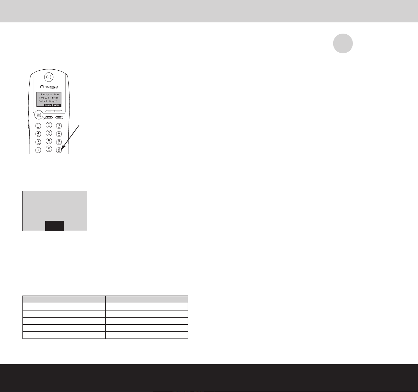
To access the Answering System (i.e., retrieve messages) from your Handset or Console (Figure 52):
1. Press #
Answering System
Figure 52: # Key on Handset
The display will change to indicate Answering Machine Operation. At the same time an audio message will be presented.
Audio Message Example: Saturday, 7:15 am, 2 New Messages and 4 Old Messages, System is Armed. To play
incoming message, press 2, for help press 0.
i
The # button has an envelope icon
next to it to represent “messages”
aka Answering System.
Answering Machine
Operation
EXIT
Retrieving Incoming Messages
To listen to your telephone messages from the Handset or Console:
1. Press #
2. When prompted, press 2
While listening to your messages, the following commands are available
Key Command Command Enabled
Press 1 Repeat Message
Press 2 Play Messages
Press 3 Skip Message
Press 4 Delete Message
Press 5 Stop/Start Message
Table 5: Listening to Your Messages, Options
[www.LifeShield.com]
(Table 5)
:
USING YOUR TELEPHONE SYSTEM
[82]
Page 24
Answering System Operation
Answering System Settings
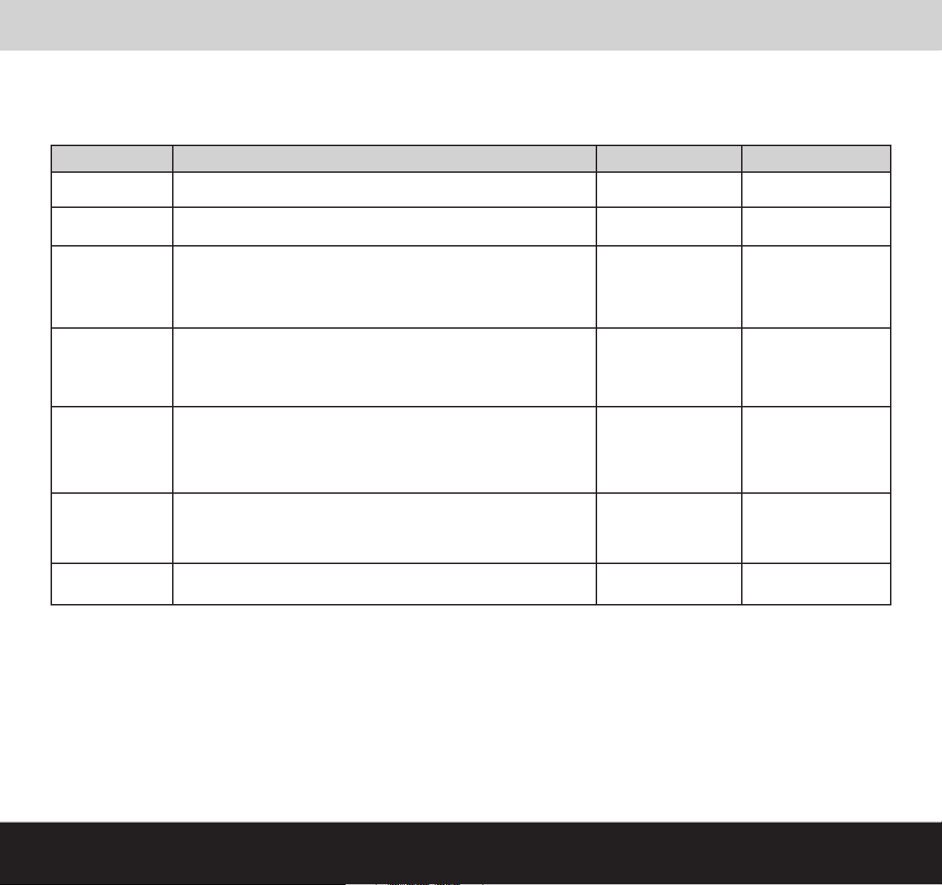
The Answering System has factory settings, but may be customized through the menus on your Handset or Console.
Depending on your preferences, you can customize the settings for each LifeShield phone through the menu on your Handset or Console.
Function Setting Description Setting Options Factory Setting
Answering System Turn Answering System on or off. On/Off Off
Number of Rings Set the number of rings before the Answering System picks up the call. 0/2/4 Rings 4 Rings
See Answering System Settings in Table 6
.
Set the Answering System maximum record time for calls.
Max Record Time
Toll Saver
Direct to Answer
Call Screening Play caller messages as they are being recorded from the Handset and Console.
Select Greeting Select a standard greeting or record a personalized greeting.
Table 6: Answering System Settings
The Announce Only setting presents the caller with your greeting, but
does not allow their message to be recorded.
When there are new messages in the Answering System, an incoming call
will be answered after 2 rings instead of the configured number of rings to
save a toll when retrieving remotely.
Based on Caller ID information and this setting, the Answering System
will record the call without the phone ringing.
Announce Only
1 Minute
4 Minutes
On/Off Off
Off
No Caller ID
Not in Phone Book
All
Off
Handset
Console
Standard
Personalized
4 Minutes
Off
Off
Standard
[83]
USING YOUR TELEPHONE SYSTEM
[www.LifeShield.com]
Page 25
Changing Answering System Settings
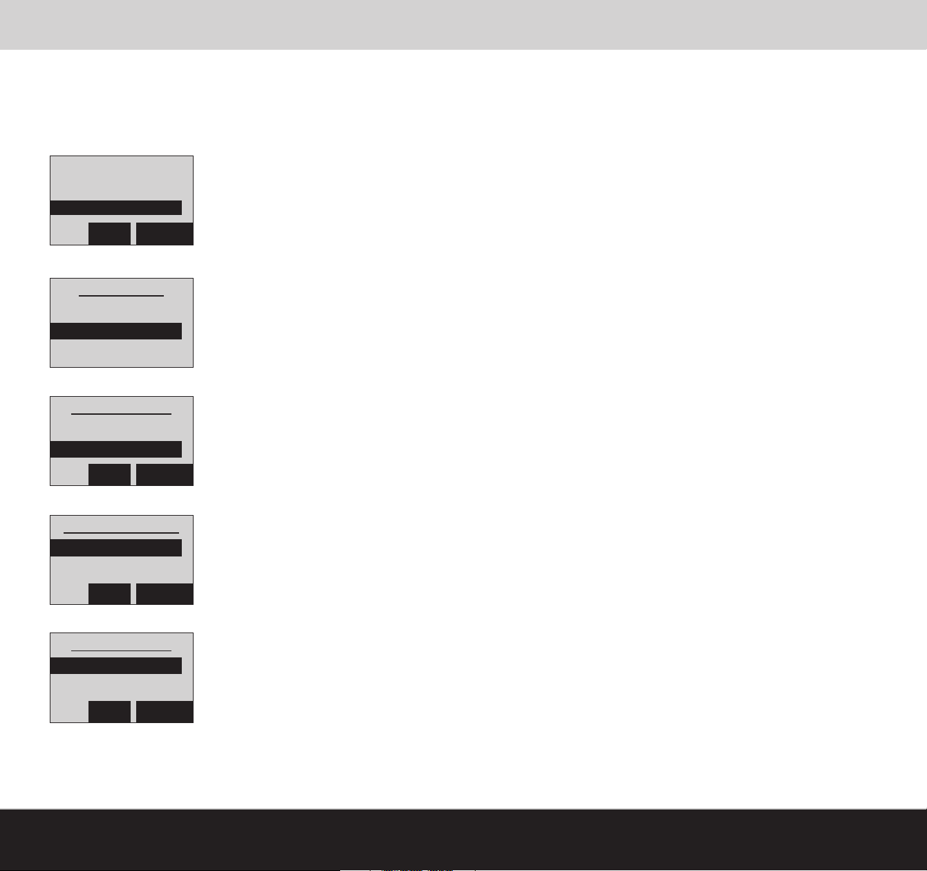
To configure the Answering System:
1. Press MENU
2. Scroll to Phone Setup, press SELECT
Intercom
Security Setup
Phone Setup
BACK SELECT
3. Scroll to Answer System, press SELECT
Phone Setup
Handset
Answer System
4. Scroll to desired category, press SELECT (Example: Max Record Time)
Answer System
Number of Rings
Max Record Time
Answering System Operation
BACK SELECT
5. Scroll to the desired setting, press SELECT (Example: 1 Min)
Max Record Time
1 Min
4 Min
BACK SELECT
6. Upon making your selection you will be brought back to the Answering System menu
Answer System
On/Off
Number of Rings
BACK SELECT
7. Press TALK/END to return to the main display
[www.LifeShield.com]
USING YOUR TELEPHONE SYSTEM
[84]
Page 26
Answering System Operation
Call Screening
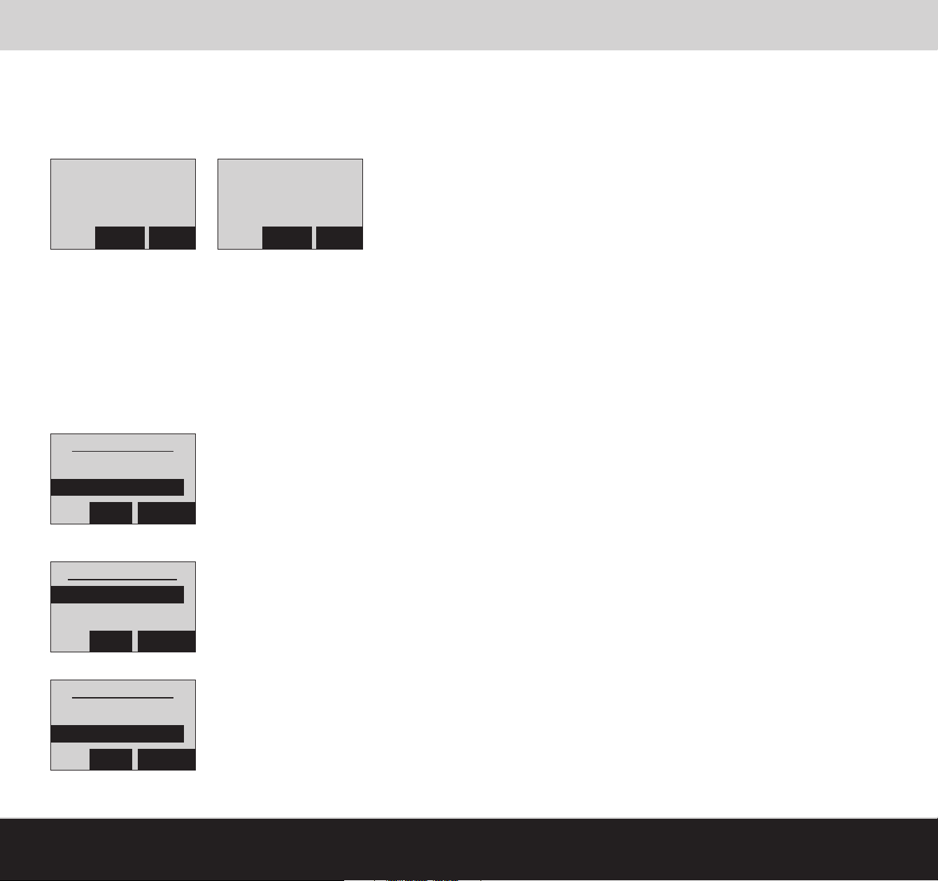
The Call Screening feature plays incoming call messages over the speaker as they are being recorded. A Handset or Console
can be selected as the “call screening” device. Only one unit at a time can be the screener.
If Call Screening is enabled, the system will flash between presenting “Caller ID” info and “Call Screening” on the display.
Ready to Arm
Incoming Caller Name
Incoming Caller Number
QUIET STOP
Ready to Arm
Call Screening
QUIET STOP
Pressing the QUIET key at any time during the recording will continue recording without broadcasting over the speaker phone.
Pressing the STOP key at any time during the recording will end the call.
Enabling Call Screening:
1. Press MENU
2. Scroll to Phone Setup, press SELECT
3. Scroll to Answer System, press SELECT
4. Scroll to Call Screening, press SELECT
Answer System
Direct to Answ
Call Screening
BACK SELECT
5. Scroll to desired call screening setting, press SELECT
Call Screening
Off
Handset Name
BACK SELECT
6. Upon making selection you will be brought back to the Answering System Menu
Answer System
Direct to Answ
Call Screening
BACK SELECT
7. Press TALK/END to return to the main display
[85]
USING YOUR TELEPHONE SYSTEM
[www.LifeShield.com]
Page 27
Answering System Operation
Select and Record Greeting
The LifeShield Answering System has a prerecorded greeting or you can record your own greeting.
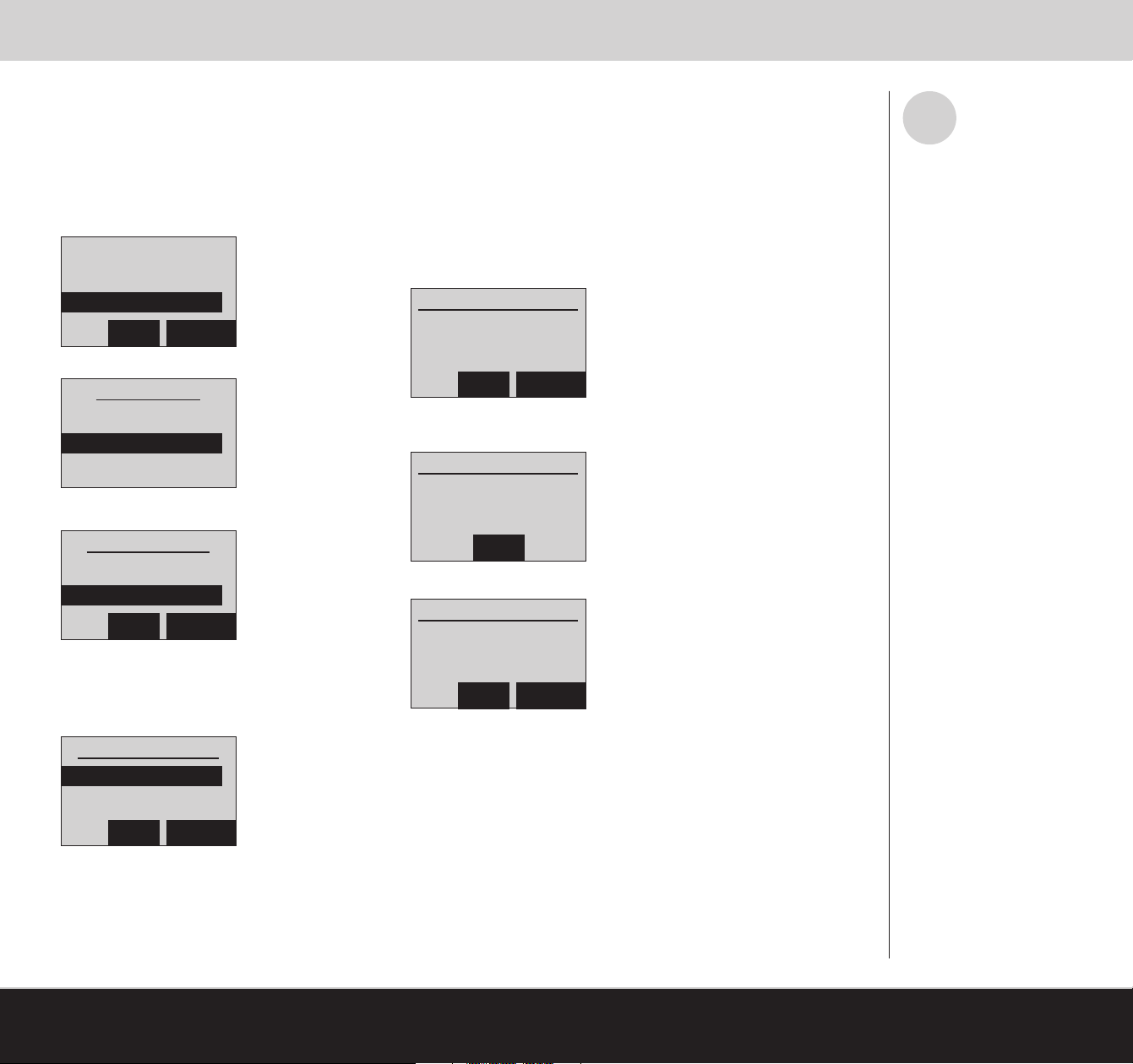
To Select Greeting:
1. Press MENU
2. Scroll to Phone Setup, press SELECT
Intercom
Security Setup
Phone Setup
BACK SELECT
3. Scroll to Answer System, press SELECT
Phone Setup
Handset
Answer System
4. Scroll to Select Greeting, press SELECT
Personal Greeting
6. Scroll to Personal Greeting, press SELECT
7. If no personal greeting has been recorded, the
following display appears:
Personal Greeting
No personal
greeting recorded
BACK RECORD
8. Press RECORD
9. Audio beep begins recording time; remaining time counts down
Personal Greeting
Recording
30 Seconds
i
The greeting must be more than 2
seconds or it will not be recorded.
Scroll to Play, Rerecord or Accept;
press SELECT.
Answer System
Call Screening
Select Greeting
BACK SELECT
Standard Greeting
5. Scroll to Standard Greeting, press SELECT
The greeting will be played
Select Greeting
Standard
Personal
BACK SELECT
[www.LifeShield.com]
STOP
10.
At the end of your recording press STOP
Personal Greeting
Play
Rerecord
Accept
BACK RECORD
11. Scroll to Play, Rerecord or Accept; press SELECT
To record a personal greeting from the Answering System Operating
menu follow these steps:
1. Press # key
2. Press 8 when prompted
3. After tone, begin recording a personalized message
4. Press 5 to stop recording
The greeting will automatically play back at the end of your recording.
USING YOUR TELEPHONE SYSTEM
[86]
Page 28
Privacy/Do Not Disturb (DND)
Privacy
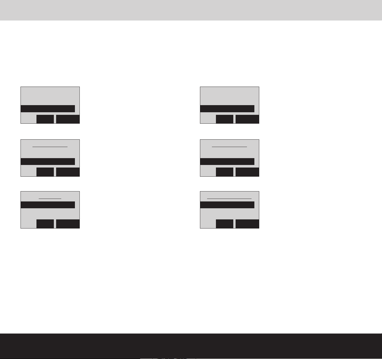
Enabling the Privacy feature on your phone system will prevent other phone
devices within your home from listening to your call.
To enable Privacy:
1. Press MENU
2. Scroll to Phone Setup, press SELECT
Intercom
Security Setup
Phone Setup
BACK SELECT
3. Scroll to Privacy, press SELECT
Phone Setup
Answer System
Privacy
BACK SELECT
4. Scroll to On, press SELECT
Privacy
Off
On
Do Not Disturb (DND)
Enabling the Do Not Disturb feature on your phone system will mute the
ring tones on all incoming calls.
To enable DND:
1. Press MENU
2. Scroll to Phone Setup, press SELECT
Intercom
Security Setup
Phone Setup
BACK SELECT
3. Scroll to Do Not Disturb, press SELECT
Phone Setup
Privacy
Do Not Disturb
BACK SELECT
4. Scroll to On, press SELECT
Do Not Disturb
Off
On
BACK SELECT
5. This selection will bring you back to the Phone Setup menu
6. Press TALK/END to return to the main display
[87]
USING YOUR TELEPHONE SYSTEM
BACK SELECT
5. This selection will bring you back to the Phone Setup menu
6. Press TALK/END to return to the main display
[www.LifeShield.com]
Page 29
Setting Up an Intercom Session
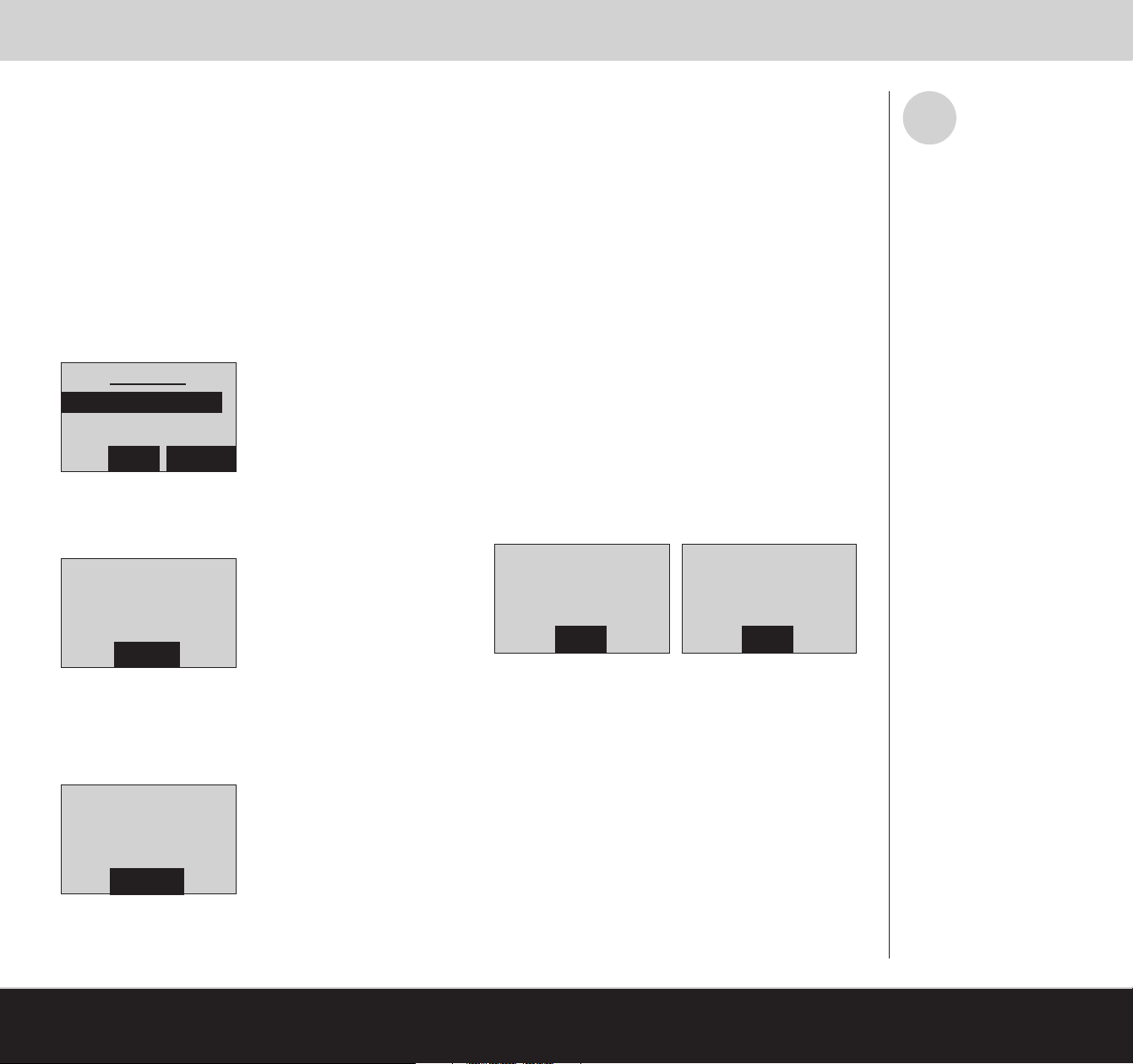
The Intercom feature allows a 2-way conversation between 2 LifeShield phones (Handset or Console) in your system. The
Intercom is available as long as the receiving phone (Handset or Console) is not in use.
Setting Up an Intercom Session
To establish an Intercom session:
On the Calling Phone:
1. Press MENU
2. Scroll to Intercom, press SELECT
3. Scroll to the desired Receiving Phone, press SELECT (Example: Console 1)
Example: Calling Phone Display
Intercom
Console 1
BACK SELECT
i
Either party may end an Intercom
session by selecting the End key.
If the requested device is being
used when an Intercom session is
started, the originating device will
show “Unavailable” on the
display and sound an error beep.
4. Both LifeShield phones will display a
message that says Connecting
Example: Calling Phone Display
Intercom To
Consle 1
Connecting
CANCEL
5. Both LifeShield phones will beep and the display will indicate: Intercom From:
(Example: Handset 1)
Example: Receiving Phone Display
Intercom From
Handset 1
ANSWER
6. Both LifeShield phones indicate an Intercom
call is in progress
Ready to Arm
Thu 2/8 11:48a
Intcm: Handset 1
END
Ready to Arm
Thu 2/8 11:48a
Intcm: Console 1
END
If the phone rings while an Intercom call is in progress
the Intercom call can continue or the incoming call can be
answered. The display will show Ringing and show
Caller ID information, if available.
7. To end the Intercom session and answer the call,
either user can press TALK/END or SPKR on the
Handset or Console
[www.LifeShield.com]
USING YOUR TELEPHONE SYSTEM
[88]
Page 30
Setting Up Room Monitoring
The Room Monitor feature allows you to monitor sounds in another room, such as a nursery.
i
If the phone rings, it can be
answered from either device by
pressing the TALK button on the
Handset or Console, or the
SPEAKER key on the Handset.
A room monitoring session is
terminated by pressing the END
key on either device.
In the Room Monitor mode,
2-way communication is not
possible.
Setting Up Room Monitoring
To set up Room Monitoring:
1. With Console in one room (Receiver Phone), place another LifeShield phone (Example: Handset 1) in the room you would
like to monitor (Monitored Phone).
On the Receiver Phone:
2. Press MENU
3. Scroll to Room Monitor, press SELECT
4. Scroll to the Monitored Phone, press SELECT (Example: Handset 1).
Example: Receiver Phone Display:
Room Monitor
Handset 1
BACK SELECT
5. This selection will connect the 2 LifeShield phones. The message Connecting appears on the display.
[89]
Example: Receiver Phone Display:
RmMon To:
Handset 1
Connecting
CANCEL
6. When the phones are connected, their names appear on each other’s display.
Example: Receiver Phone Display Example: Monitored Phone Display
Ready to Arm
Thu 2/8 11:48a
RmMon: Console 1
END
Thu 2/8 11:48a
RmMon: Handset 1
USING YOUR TELEPHONE SYSTEM
Ready to Arm
END
[www.LifeShield.com]
Page 31
Enable Remote Access/Use Remote Access
You can access your Answering System or security functions from a remote location. The factory default for remote access is
On, but can be disabled through the configuration settings. The Remote Access Menu is voice-prompt driven.
Disable Remote Access
To disable remote access on your Handset or Console:
1. Press MENU
2. Scroll to Security Setup, press SELECT
3. Enter your Master Code
4. Scroll to Remote Access, press SELECT
5. Scroll to Off, press SELECT (Example: On)
Use Remote Access
To access the system:
1. Dial your home number and wait for the system to answer
2. Select the asterisk button (*) and enter your User Code when the system answers
3. Upon entering a valid User Code the system will announce the state of your Answering and Security systems
Example Audio Message:
“Sunday 7:15 PM”
“2 new messages and 5 old messages”
“The system is Armed – Stay”
“To play Incoming Message, select 2.”
“To enter Security Menu, select 9.”
“For Help, select 0.”
Answering System Access
4. To access the answering system, select 2
i
A touch-tone phone is required for
Remote Access entry.
If the LifeShield Answering
System is turned off or your telephone service provider’s voice
mail answers before the
LifeShield Answering System,
Remote Access will not operate.
A Master or Normal User code
can be used for remote access.
If the Answering System is on,
when the call is answered the
system will play the selected
Greeting. If the Answering
System is off, after 10 rings the
system will answer and a
waiting tone will sound once every
2 seconds.
!
WARNING - Arming your
system remotely can lead to
false alarms if someone at
home is not aware that you
are arming the system.
Security System Access
5. To access the security system, select 9
The following Security System commands are available:
To Arm Stay, select 1
To Arm Away, select 2
To Disarm or Cancel, select 4
To Bypass All Not Ready Sensors, select 5
To start the Intercom, select 6 (this enables remote intercom into your home)
To return to Answering System, select 9
For Help, select 0
[www.LifeShield.com]
USING YOUR TELEPHONE SYSTEM
[90]
Page 32
Expand Your System
Expand Your System
Additional components may be added to your system, up to the maximum shown in Table 7.
Components Maximum Components Per System
Base 1*
Handsets 6*
Consoles 4*
Grid Extenders 4*
Door Sensors 50
Window Sensors 50
Siren Detector Sensors 50
Motion Sensors 50
Smoke Sensors 50
Glassbreak Sensors 50
Environmental Sensors (Water/Temperature) 50
Keychain Remotes 4
Cameras 4
Table 7: Maximum Number of Devices Supported
*The system will support a total combination of 8 Handsets, Consoles or Grid Extenders. The system will support a total combination of 50 Sensors of any
kind listed in the table.
To purchase additional system components, go to www.LifeShield.com or call LifeShield Customer Support 1-888-392-2044. For instructions on adding
additional components to your system see the Device Guides provided inside your device packages.
[91]
SUPPLEMENTAL INFORMATION
[www.LifeShield.com]
Page 33

Glossary
Alarm
The sound that is heard when your system is armed and a Sensor has been faulted or when the PANIC button has been pressed.
Alarm Notification Delay
When an alarm sounds, a notification signal is sent to the Alarm Monitoring Center after a delay of 30 seconds. The delay provides time for you to cancel a false
alarm.
Arming Your System
Arming Your System means turning your system on to secure your premises.
Auto Answer
When enabled, a call will be active when the Handset is picked up off the Charging Cradle. TALK/END does not need to be pressed.
Auto Stay
When the system is armed Away, but you don't leave the house, the system defaults back to armed Stay status. To override this default setting Auto Stay can be
set to "No" on LifeShield.com.
AWAY (Leaving Home)
Arm AWAY when leaving your home. All Sensors are monitored (except those designated as a “Non-Monitored Type”). An audible Exit Delay and Entry Delay is
supported.
Base
One of 3 Grid Controllers. The Base provides the system Internet access and phone line backup.
Bypassing a Sensor
Bypassing a Sensor allows you to arm your system without monitoring or creating an alarm condition when a Sensor is opened.
Charger
The Charger is provided with, and is used to charge, the Handset.
Chime
A Chime is the sound made when a Sensor is opened or closed. Chimes can be turned off globally from both the Handset and Console by pressing the Chime button and entering your User Code.
Comm. Test
The communication test verifies alarms can be sent across both the Internet and your phone line to the Alarm Monitoring Center. This is done automatically during
activation, but should be run periodically to verify communications.
Console
One of 3 Grid Controllers. The Console provides full feature display and keypad for operating the system.
Direct to Answer
Direct to Answer sends an incoming call directly to the Answering System, rather than answering the call.
Disarming Your System
Turning your security system off. Disarming your system is done by pressing CANCEL/Off on your Handset or Console and then entering your User Code.
Display Messages
Messages on the screen of your Handset or Console. Line 1 displays security status messages. Line 2 displays secondary security status messages. Line 3
displays phone status messages.
[www.LifeShield.com]
SUPPLEMENTAL INFORMATION
[92]
Page 34

Glossary
Do Not Disturb (DND)
Do Not Disturb feature mutes the ring tone on all incoming calls.
Entry Delay
Entry Delay gives you time to enter your armed home and disarm the system before the alarm sounds. The system beeps during the Entry Delay. INSTANT arming
does not have an Entry Delay.
Event Logs
The system logs all monitored Events that occur on your system, such as alarms sent to LifeShield Central Monitoring. You can view these Events from your Handset, Console or LifeShield.com.
Exit Delay
The Exit Delay gives you time to leave your home before the system is armed. INSTANT does not have an Exit Delay.
Faulted
Faulted occurs when an event a Sensor is monitoring is detected, such as the opening of a door or window.
Grid Controllers (GCs)
The wireless grid in your LifeShield Home Security system is created using Grid Controllers (GCs). These include the Base, Console and Grid Extenders. Together
they communicate with Sensors to create a blanket of protection for your entire home.
Grid Extender
Grid Extenders are 1 of 3 system Grid Controllers added to your system to fill in wireless coverage not covered by the Base or Console. You can add more than one
Grid Extender to your system.
Handset
The Handset provides mobile control of your security system and comes with a charging cradle and power supply. It is also a full-featured cordless, Wi-Fi friendly
digital telephone. The Handset can be charged by placing it in the charging cradle.
Home Alerts
Home Alerts are messages regarding important information about your security system. Home Alerts are indicated by an icon on your Handset,
accompanied by the Alert light illuminating red.
Home Connect
The Home Connect feature allows you to monitor another home that has a LifeShield Home Security system. Home Connect must be set up on the LifeShield
website. You can connect to a Home Connect participant by selecting the CONNCT button on your Console or Handset. Home Connect allows you to arm and
disarm another system and receive alarm notifications regarding that system.
INSTANT
Arm Instant when in for the evening and not expecting anyone to enter or leave from your home. There is no Entry or Exit Delay supported and an alarm will sound
immediately upon faulting an armed Sensor.
Intercom
The Intercom feature allows 2-way conversations with another Handset or Console in the system.
In-Test
You can request your system be put In-Test for up to 24 hours. During this time your system will not be monitored.
Keychain Remote
A Keychain Remote allows you to arm your security system from outside your home.
[93]
SUPPLEMENTAL INFORMATION
[www.LifeShield.com]
Page 35

Glossary
LifeShield.com
www.LifeShield.com provides complete control, configuration, and status of your system from any PC or Mac Internet browser.
Master Code
One Master Code is supported, which you entered as part of your activation process. Only the Master Code can be used to change your system settings, such as
creating, editing and deleting other User Codes.
Mobile LifeShield
mobile.LifeShield.com can be accessed from any web enabled mobile device to arm/disarm, check system status, recent events, and access cameras. Must be
first enabled in www.LifeShield.com under top status panel, Quick Links, Preferences.
One Touch Arming
When enabled on www.LifeShield.com the system can be armed by pressing and holding Stay, Away, or Instant on the Handset or Console without entering your
User Code. The factory default is Off.
PANIC Alarm
A PANIC Alarm generates an alarm and the Alarm Monitoring Center contacts emergency authorities without phone call verification. The PANIC Alarm is generated
by pressing the PANIC button located on the Handset and Console.
Phone Book
The built-in phone book can store up to 99 telephone numbers and/or Caller ID messages.
Practice
After a system is activated, it is in Practice mode for 7 days. Practice mode allows you to learn the system without causing false alarms. During this time you are
"Not Monitored" and there will be NO dispatch of authorities.
Remote Access
Your LifeShield system allows you to dial in to your home from any cell phone or telephone to arm, disarm or control other aspects of your system.
Room Monitor
The Room Monitor allows for monitoring sounds in another room by use of LifeShield Handsets and Consoles.
Sensors
Sensors monitor events and, when detected, report the event back to the LifeShield System.
Sensor Brackets
The hardware used when mounting the Sensors.
Sensor Extensions
Sensor Extensions are used if your door frame does not provide enough room for mounting the Sensor bracket. Sensor Extensions allow you to place a Sensor in
an area up to 18” away where more room is available.
Sensor Magnets
Magnets are used with door/window Sensors. Magnets are attached to a door or window, while the Sensor is attached to a door or window frame.
STAY
Arm Stay while you are at home. A silent Exit Delay and an audible Entry Delay is supported. An audible Exit Delay can be enabled on LifeShield.com.
User Codes
User Codes can arm and disarm your system, but cannot access or change your system settings.
[www.LifeShield.com]
SUPPLEMENTAL INFORMATION
[94]
Page 36
General Troubleshooting
The table below provides you with a list of typical trouble conditions and how to potentially resolve them.
Trouble Indication Trouble Symptom Possible Solutions
Out of Range
No Phone Line/No Dial Tone
LoBat: <Handset Name>
LoBat: <Grid Controller
Name>
(Grid Controller) (GC)
1) Handset or Console has limited or
no functionality.
2) Display indicates “Out of Range”
1) Handset or Console has limited
or no “Phone” functionality (no
dial tone)
2) Display indicates no phone line
3) Trouble beep
1) Display indicates Handset has
reduced range or low battery
2) Trouble beep
Display indicates low battery in the
designated device
Handset or Console must be within 200 feet of system. Move devices closer to system
until “Out of Range” message disappears.
Verify that a phone line is plugged into one of the existing GCs (Base, Grid Extender or
Console). If not, plug in a phone line.
Verify that the phone line from the GCs is plugged into a wall phone jack or phone
device (VoIP box). If not, plug in the phone line to the phone jack.
Verify that your existing wall jack or phone box (VoIP) is active by verifying you have a
dial tone on an existing phone. If not, check with your phone service provider.
Place Handset in your Charging Cradle for at least 2 hours to recharge the Handset.
Verify that the GC has the battery connected. If not, connect the battery.
Verify that the GC is plugged into an electrical wall outlet. The Handset or Console
display will indicate if there is no power applied to the GC. Plugging in the GC to a live
electrical wall outlet will recharge the battery.
LoBat: <Sensor Name>
(Sensor)
NoA/C: <Grid Controller
Name>
(Grid Controller) (GC)
[95]
SUPPLEMENTAL INFORMATION
1) Display indicates Sensor has a
low battery
2) Trouble beep
1) Display indicates a Grid Controller
has lost AC power
2) Trouble beep
Replace the battery in the Sensor.
Verify that the power supply of the device is plugged into a wall outlet.
Verify that the outlet is not controlled by a wall switch.
Check the circuit breaker or fuse box and make sure power to the outlet is on. If the
outlet still is not working, contact a qualified electrician for service.
[www.LifeShield.com]
Page 37
General Troubleshooting
Trouble Indication Trouble Symptom Possible Solutions
A handset may have been removed from the system after installation. Removal
could mean the battery has been removed from the handset. Verify that the battery
is connected.
Lost: <Handset Name>
(Handset)
Lost: <Grid Controller
Name>
(Grid Controller) (GC)
1) Display indicates communication
has been lost to the Handset
2) Trouble beep
1) Display indicates communication
has been lost to the Grid Controller
2) Trouble beep
The handset could have been moved out of range from the system. Bring the Handset
back in range.
A structural change (interference) in the home may have changed the wireless pattern
resulting in the Handset being lost. If this interference is unavoidable, move the
Handset to a new location.
A GC may have been removed from the system after installation. Removal could mean
no power is applied to the GC or the GC has been moved out of range of the system.
Verify that the GC has power applied through the battery or electrical outlet. If not,
apply power. If you have lost power to your home, the battery should maintain a GC
connection for up to 24 hours.
Verify that the GC is within range of the system. If not, move the GC within range.
A structural change (interference) in the home may have changed the wireless pattern,
resulting in the GC being lost. If this interference is unavoidable, then move the GC to a
new location or add an additional GC to your system.
A Sensor may have been removed from the system after installation. Removal could
mean no power is applied to the Sensor (battery dead) or the Sensor and GC have
been moved out of range of each other.
Lost: <Sensor Name>
(Sensor)
[www.LifeShield.com]
1) Display indicates communication
has been lost to a Sensor
2) Trouble beep
Verify that the Sensor battery is still good by replacing it.
Verify that the GC has not been moved. It is possible that one or more GCs have been
moved and that the Sensor is no longer in the GC coverage range. Move the GC back
within range or add another GC to your system.
A structural change (interference) in the home may have changed the wireless pattern
resulting in the GC and Sensor not being within range of each other. If this interference
is unavoidable, then either move the GC to a new location or add an additional GC to
your system.
SUPPLEMENTAL INFORMATION
[96]
Page 38
General Troubleshooting
Trouble Indication Trouble Symptom Possible Solutions
The Internet Service Provider may have interrupted service. Verify that you have an
Internet connection on your PC. Contact your Internet Service Provider for diagnostics
or information regarding service outages.
The Internet cable may not be connected to the Base. Verify the Internet cable is
securely connected to the Base.
Verify that the router is operating properly (refer to the router instructions).
An IP address is required for a device to communicate with the Internet. Your router
may not be providing your Base with an IP address.
Scroll to and select Security Setup/Network Mode/Renew DHCP. This should provide
you with a new IP address.
If you have DSL service and are located in an area of the country (such as in certain
No Internet
1) Handset and Console display
indicate "No Internet"
2) Unable to obtain weather
downloads, or connect to home
connect participant
New England areas) that uses a protocol known as PPOE, check the settings for the
PPOE connection. The LifeShield system requires a continuous connection and some
PPOE routers may be configured to periodically stop the high-speed data connection.
If no IP address is assigned (Example: 0.0.0.0) go to the Network Mode Menu and
select address type “Dynamic DHCP.” If Dynamic DHCP is selected, then hit the back
button, scroll to and select Renew DHCP. You will receive a message
“DHCP Succeeded” if the IP address renewed successfully.
[97]
SUPPLEMENTAL INFORMATION
If DHCP update is not successful, the router may be configured for static addressing.
Have the subscriber refer to router’s instruction manual for setting up DHCP addressing. If the subscriber wants to keep the router set up for static addressing, see the
enclosed instruction on how to set up a Static IP address on the LifeShield System.
If an IP address is assigned, go to the Network Mode, scroll to and select Renew DHCP.
You will receive a message “DHCP Succeeded” if the IP address renewed successfully.
If renewing the IP address was not successful, restart the router. After restarting the
router and all router lights are locked on the router, check the LifeShield system again
to see if an IP address has been assigned. Press Menu, scroll to Security Setup, enter
in the 4-digit Master Code, scroll to and select Network Mode, scroll to View/Edit, select IP address and verify that an IP address has been assigned.
[www.LifeShield.com]
Page 39
General Troubleshooting
Trouble Indication Trouble Symptom Possible Solutions
Move closer to system if beginning to exceed range “>200 feet.” Make sure
when using the phone you are not near a microwave oven that is in use.
Make sure when using phone you are not in close proximity to another 2.4GHz source
or Wi-Fi device (802.11). If you have DSL service, make sure all devices using the
telephone line have DSL filters installed.
Verify that the battery pack is connected properly.
Verify that the charging light is illuminated (amber) on the front of the Charging Cradle
when the Handset is placed in the Cradle. This will indicate that you have the Handset
properly seated and that you have power to Cradle. If the charging light is not illuminated see Charging Cradle Light Not Illuminated.
Verify that the contacts on the Base or Charging Cradle are clean.
If the outlet is working, allow the battery 24 hours to recharge. If the LowBat condition
persists, contact LifeShield Customer Support.
Phone Noise/Static
Handset Not Recharging
Phone noise or static while talking on
the phone
1) LoBat: Handset display
screen blank
2) Console indicates Lost (Handset)
Charging Cradle Light
Not Illuminating
LifeShield Device Will
Not Power Up
[www.LifeShield.com]
Verify that the Handset is properly placed in the Cradle.
If the Handset is properly placed in the Charging Cradle, verify that you have power
applied to the Charging Cradle.
Verify that the power supply is plugged into the Cradle.
Verify that the power supply is plugged into the electrical wall outlet.
Verify that the electrical wall outlet is not controlled by a switch which is off.
Check the circuit breaker or fuse box and make sure power to the outlet is on. If the
outlet is still not working, contact a qualified electrician for service.
Verify that the battery pack is installed.
Verify that the power supply is connected to the device and plugged into an
AC outlet that is not controlled by a switch.
Check the circuit breaker or fuse box and make sure power to the outlet is on.
If the outlet is still not working, contact a qualified electrician for service.
SUPPLEMENTAL INFORMATION
[98]
Page 40
General Troubleshooting
Trouble Indication Trouble Symptom Possible Solutions
Keychain Remote Does Not
Operate Properly
Adding Sensor Fails
(During Installation)
1) A system Keychain Remote
does not work
2) The system does not respond
to the commands of a Keychain
Remote
1) Not able to add Sensor
2) No GCs heard Sensor
Verify that you are not out of range from a GC (15 feet).
Verify that the battery is installed.
Verify that you have registered the Keychain Remote and created a
User Code for that Keychain Remote.
If no blinks or audible beeps occur, replace battery.
Relocate or add a GC to a location closer to where the Keychain Remote is normally used.
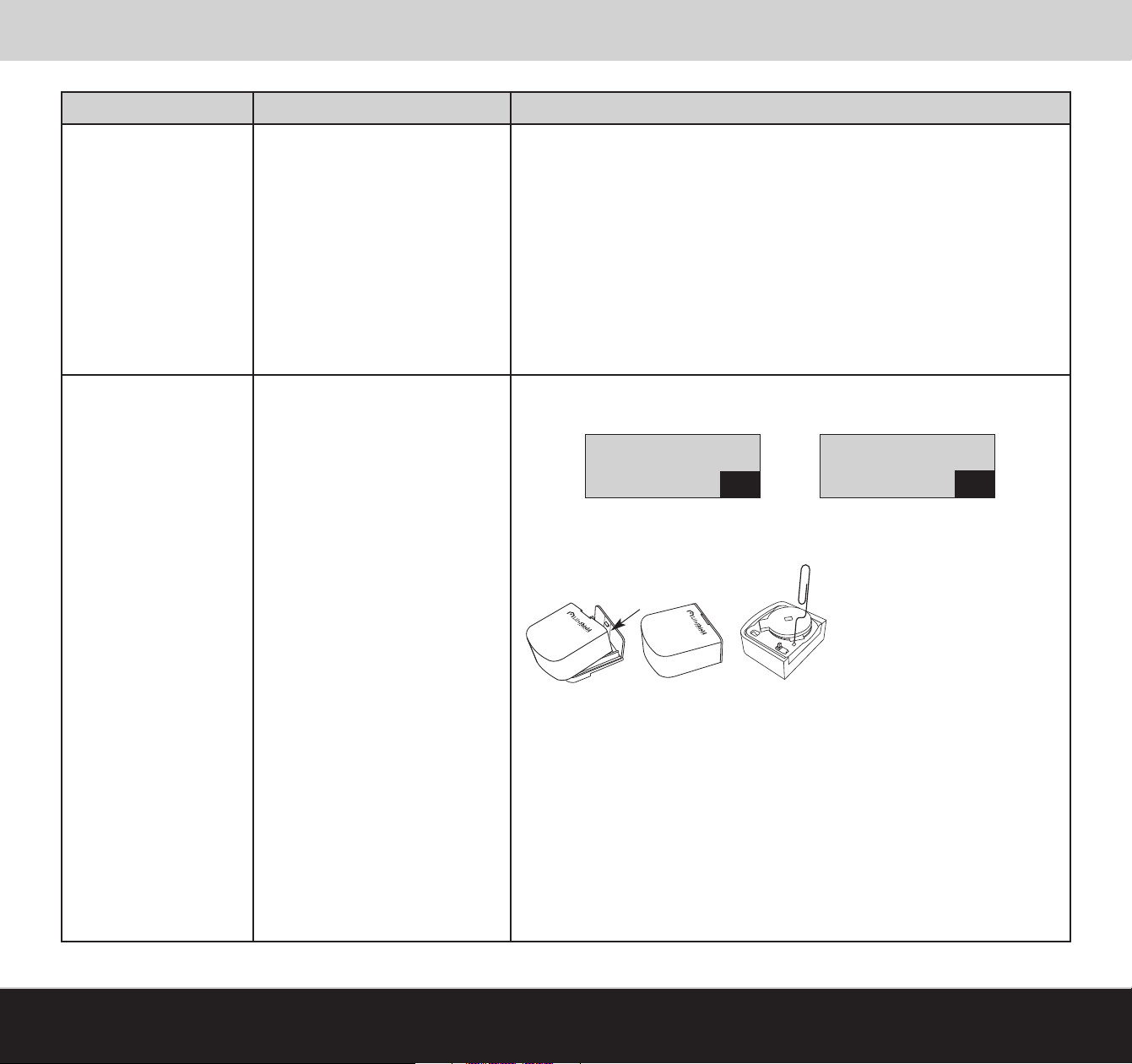
If your system can not detect a Sensor that you are trying to add, the
Handset or Console displays 1 of 2 possible error messages.
Sensor Not Found
OK
1. Retry: Press OK. Using the slot provided on the top of the Sensor, lightly pry the Sensor
away from the mounted bracket. Reset Sensor by inserting paperclip into reset hole.
Repeat Add Sensor process.
2. Replace Sensor Battery: press OK. Repeat Sensor Add process. If this does not work,
proceed to Step 3.
No GCs Heard
Sensor
OK
If this does not work,
proceed to Step 2.
[99]
SUPPLEMENTAL INFORMATION
3. Add New Sensor: Press OK. Remove Sensor. With new Sensor repeat Sensor Add
process using existing Bracket. If this does not work, proceed to Step 4.
4. Move Grid Controller: Move one of your GCs (Console, Base or Grid Extender) closer
to this Sensor mounting location. The most flexible choice for this is the Grid Extender.
If this does not work, proceed to Step 5.
5. Add Grid Controller: If you still can not successfully add a Sensor, you may need to add an
additional GC.
[www.LifeShield.com]
Page 41
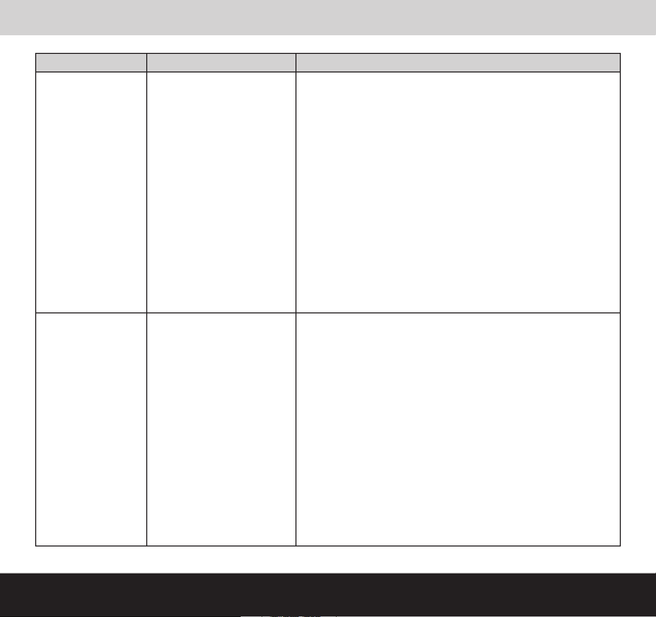
General Troubleshooting
Trouble Indication Trouble Symptom Possible Solutions
Verify that the Sensor is not lost. The system will indicate on the Handset or Console
display if the Sensor is lost. If it is lost, see the Lost Sensor Troubleshooting section.
Verify that the Sensor and Magnet are less than ¾” from each other.
Verify that the Magnet is not mounted on a steel door. If it is, you may need to
No “Sensor Open” Display
No display indication on Handset or
Console when window or door has
been opened
add a spacer underneath the Magnet to buffer it from the door or move the
Magnet and Sensor closer.
Verify that the Sensor was successfully added to the system. If you have not named
your Sensors, you may need to trip each of your system Sensors to isolate the one in
question.
See the Sensor Installation Troubleshooting section.
If situation persists, contact LifeShield Customer Support.
No “Sensor Open” Chime
[www.LifeShield.com]
No chime heard when door
or window opens
Sensor may have stopped communicating and, therefore, is lost. The system will
indicate on the Handset or Console display if a Sensor is lost. If a Sensor is lost, see
the Lost Sensor Troubleshooting section.
Verify that the Handset or Console display indicates that a Sensor is opened and
closed when the door or window is opened and then closed. If not, see the No Sensor
Open Display Troubleshooting section.
Verify that the Chime has been turned on from the Handset or Console. If not, select
Chime from either the Handset or Console and enter your User Code.
Verify that the Chime has been enabled from the LifeShield website for the Sensor in
question. If not, go to www.LifeShield.com, go to Settings tab, go to the Sensors panel,
click on Edit adjacent to the desired Sensor and enable the Chime for that
Sensor.
SUPPLEMENTAL INFORMATION
[100]
Page 42
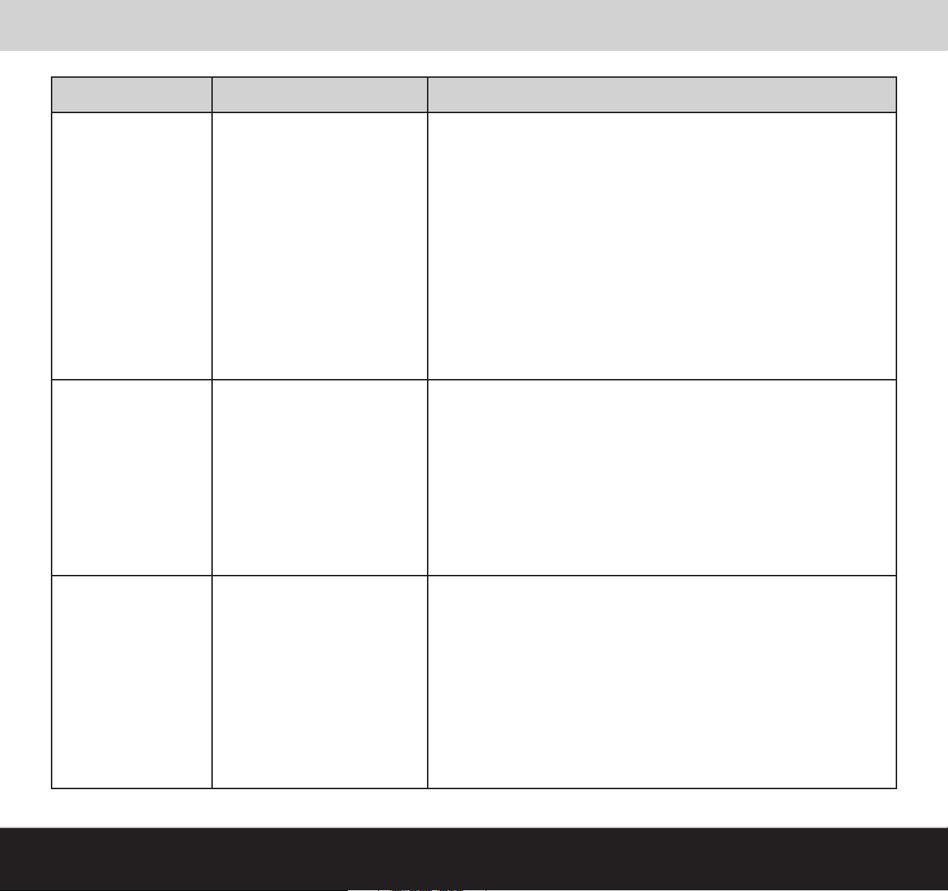
General Troubleshooting
Trouble Indication Trouble Symptom Possible Solutions
Verify the phone line is not being used by someone else within the home. The display
on the LifeShield phone will indicate Line in Use. If so, rerun test when the line is not
being used.
Comm. Test Fails
(Telephone Line Fail)
Comm. Test Fails
(Internet Fails)
Telephone line did not successfully
communicate with the Alarm Monitoring Center
Internet line did not successfully
communicate with the Alarm Monitoring Center
Verify that one of your GCs has a phone line connected to an active phone jack. If not,
connect a phone line to either the Base, Console or Grid Extender.
The telephone interface may be improperly wired. Verify the telephone connection is
working by plugging a different telephone into the jack and listening for a dial tone. If
there is no dial tone, contact the telephone company or qualified technician.
Verify that you have activated your system via www.LifeShield.com. The
Handset/Console displays Not Activated, if the system is not yet activated.
See the No Internet Troubleshooting section.
Verify that the system has been activated. The display will show Not Activated if it has
not been activated.
[101]
Not Monitored
SUPPLEMENTAL INFORMATION
Your emergency information may not have been obtained or verified.
Call LifeShield Customer Support at 1-888-392-2044
Verify you have not requested that LifeShield Monitoring put the system in Test mode.
.
[www.LifeShield.com]
Page 43
System Messages
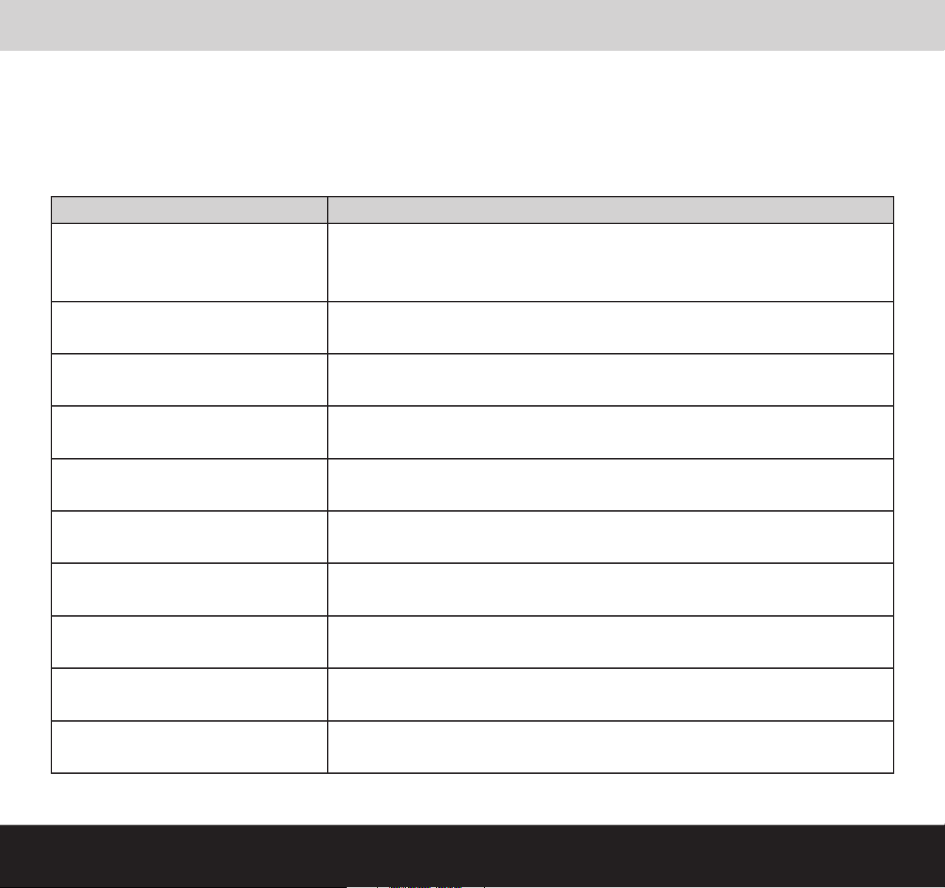
Display Messages Overview
The Console and Handset serve as your primary interface to control, configure and view your LifeShield Home Security system. These devices each have a
high-resolution digital display with 3 lines of specific message categories, including those shown in the tables that follow.
Primary Security Display Messages
The following table lists and describes the Primary Security Display Messages of your LifeShield Home Security system.
Display Message/States Display Description
Ready to Arm Message displayed on the Handset and Console when the system is Ready to Arm.
Message displayed when system is Not Ready to Arm due to an open Sensor. The open Sensor
Not Ready to Arm
Armed Stay Message displayed when the system is in Armed-Stay mode.
Armed Away Message displayed when the system is in Armed-Away mode.
must either be closed or bypassed before the system can be armed. The second line of the
display indicates which Sensor is open.
Armed Inst Stay Message displayed when the system is in Armed-Instant mode.
Arming Stay Message displayed immediately after you’ve selected the Stay button on either the Handset or Console.
Arming Away Message displayed immediately after you’ve selected the Away button on either the Handset or Console.
Arming Instant Message displayed immediately after you’ve selected the Instant button on either the Handset or Console.
Alarm Message displayed when the system is Alarming.
Exit Alarm Message displayed when a Sensor is open and the Exit Time has expired.
Table 8: Primary Security Display Messages
[www.LifeShield.com]
SUPPLEMENTAL INFORMATION
[102]
Page 44
System Messages
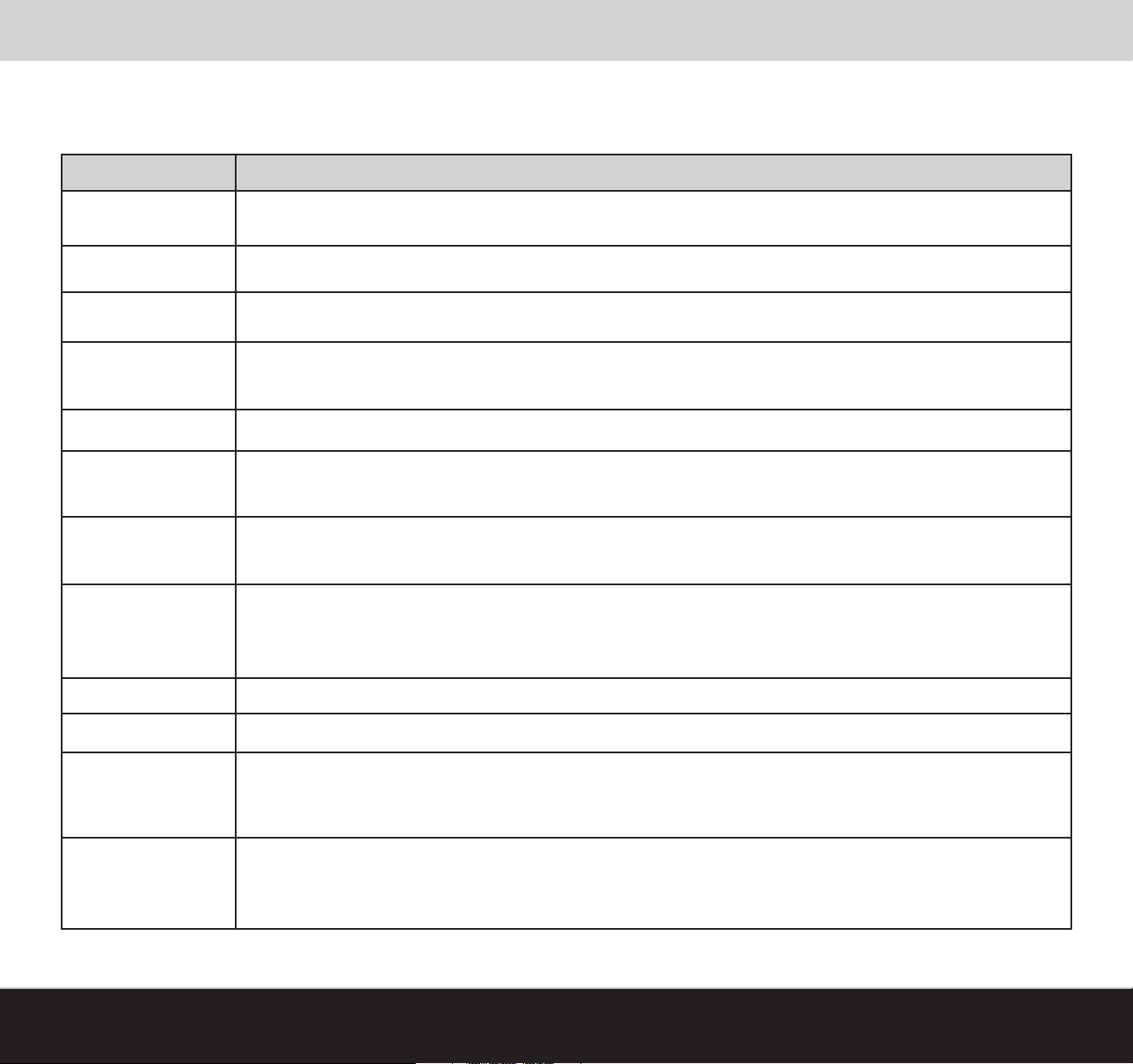
Secondary Security Display Messages
The following table lists and describes the Secondary Security Display Messages of your LifeShield Home Security system.
Display Message Display Description
Not Monitored Message displayed when the system is Armed but is not being monitored by the Alarm Monitoring Center.
Synchronizing Message displayed if the system has temporarily lost grid communication and is in the process of reestablishing.
Not Activated Message displayed if the system has not been activated.
Not Registered
Bypass on Message displayed when a Sensor has been bypassed.
No Phone Line
No Internet
LoBat: Device Name:
Sensor Name Open Message displayed when Sensor is faulted (open).
NoA/C: Device Name: Message displayed when a device has lost AC power.
Lost Device:
Device Name:
Message displayed on a Handset or Console if that device has not been registered into any system. The Handset or Console
cannot perform any functions until it has been registered into a system.
Message displayed when the system detects that your phone line has been disconnected from one of the GCs. If a phone line is
available at another GC, the system will reconfigure itself in approximately 10 seconds.
Message displayed when the system has lost communications to the Internet. This can be caused by a network outage by your broadband provider,
loss of AC power to your cable or DSL modem, a PPOE problem, loss of power to your router, failure of the router, or a wire disconnection.
Message displayed when a device has a low battery condition. If the device is a Handset, place the Handset on a Base or Charger.
If the device is a Base, Console, or Grid Extender, make sure that the battery is connected and AC power is available to charge the
battery in the device. If the device is a Sensor or Keychain Remote, the battery is not rechargeable and must be replaced.
Message displayed when the system has lost communications with one of the devices in the system. The device may have lost
power or been moved out of wireless range of the system. During a system reset, this message may be displayed temporarily
while the system is reconfiguring itself.
Day, Date and Time
Example: Thurs. 12/20
3:05p
Table 9: Secondary Security Display Messages
[103]
SUPPLEMENTAL INFORMATION
The time and date will be displayed when there are no system messages to display.
[www.LifeShield.com]
Page 45
System Messages
Telephone Display Status Messages
The following table lists and describes the Telephone Display Status Messages of your LifeShield Home Security system.
Display Message Display Description
Calls: 0 Msg: 0 Calls: The number of new calls. Msg: The number of messages.
Line in Use Message displayed on the LifeShield phones that are
Out of Range Message displayed if you are
Ringing
Call Screening
Talk 1:23:45 Message displayed when you are actively talking on a LifeShield Phone. The running duration of the call is also displayed.
Spkr 1:23:45
Muted 1:23:45
Call on Hold Message displayed when you are talking on a LifeShield phone and have selected to put the caller on hold.
Privacy Active
Message displayed when there is an incoming call prior to either you picking up the call or the Caller ID being engaged.
(Caller ID may be available from your phone service provider.)
Message displayed during a call if you have activated Call Screening on your telephone. During Call Screening, incoming calls
are sent to the Answering System. While the call is being recorded, it is presented to you on the speaker phone. Your phone has
Call Screening deactivated as the factory setting. You can activate it through the Menus on your phone.
Message displayed when you are actively talking on a LifeShield Phone (Handset Only) and put the call on the Speaker.
The running duration of the call is also displayed.
Message displayed when you are actively talking on a LifeShield Phone and place the call on Mute. The running duration of
the call is also displayed. Mute is activated by selecting the Mute button on the Handset.
Message displayed if you have activated Privacy on your phone system. If you are talking on the phone, another family member
will not be able to join the call from another phone when Privacy is activated. Your phone system has Privacy deactivated as the
factory setting out of the box. It can be activated through the menus on your phone.
out of range
of the LifeShield phone base and try to make a call on your Handset.
not in use
when one of the other phones in your home is being used.
Message displayed when you have the Do Not Disturb feature activated on your phone system. The LifeShield phone ring will be
Do Not Disturb
Paging Message displayed when you attempt to use the LifeShield phone to page another LifeShield phone.
Unavailable
Table 10: Telephone Display Status Messages
[www.LifeShield.com]
muted when activated. Your phone system has Do Not Disturb deactivated as the default factory setting out of the box. It can be
activated through the menus on your phone.
Message displayed when you attempt to use the LifeShield phone’s intercom feature and the other LifeShield phone you are
trying to reach is unavailable.
SUPPLEMENTAL INFORMATION
[104]
Page 46

Precautions & Warnings/Warranty
FCC Information
FCC Part 15
This device complies with Part 15 of the FCC Rules. Operation is subject to the following two conditions: (1) This device may not cause harmful interference, and (2) this device must accept any
interference received, including interference that may cause undesired operation.
CAUTION:
Changes and modifications to this product not expressly approved by LifeShield, Inc. could void not
only the user’s authority to operate this device, but also the limited warranty.
Note:
This equipment has been tested and found to comply with the limits for a Class B digital device,
pursuant to Part 15 of the FCC Rules. These limits are designed to provide reasonable protection
against harmful interference in a residential installation. This equipment generates, uses, and can
radiate radio frequency energy and, if not installed and used in accordance with the instructions,
may cause harmful interference to radio communications. However, there is no guarantee that interference will not occur in a particular installation. If this equipment does cause harmful interference to radio or television reception, which can be determined by turning the equipment off and on,
the user is encouraged to try to correct the interference by one or more of the following measures:
• Reorient or relocate the radio or television receiving antenna
• Reorient or relocate and increase the separation between the LifeShield equipment and
radio or television receiver
• Connect the LifeShield equipment into an outlet on a circuit different from that to which the
radio or television receiver is connected
• Consult the dealer or an experienced radio/TV technician for help
The antenna used with this product must be installed to provide a separation distance of at least
20 cm from all persons and must not be co-located or operating in conjunction with any other antenna or transmitter.
This equipment should be serviced only by Lifeshield, Inc. or its authorized agents.
FCC Part 68
This equipment complies with Part 68 of the FCC rules and the requirements adopted by the ACTA.
On the equipment there is a label that contains, among other information, a product identifier in the
format US:AAAEQ##TXXXX. If requested, this number must be provided to the telephone company.
A plug and jack used to connect this equipment to the premises wiring and telephone network
must comply with the applicable FCC Part 68 rules and requirements adopted by the ACTA.
Registration No.: Found on the bottom of the unit.
The Ringer Equivalence Number (REN) for this is used to determine the number of devices that may
be connected to a telephone line. Excessive RENs on a telephone line may result in the devices not
ringing in response to an incoming call. In most but not all areas, the sum of RENs should not exceed five (5.0). To be certain of the number of devices that may be connected to a line, as determined by the total RENs, contact the local telephone company. For products approved after July
23, 2001, the REN for this product is part of the product identifier that has the format
US:AAAEQ##TXXXX. The digits represented by ## are the REN without a decimal point (e.g., 03 is a
REN of 0.3).
If this equipment causes harm to the telephone network, the telephone company will notify you in
advance that a temporary discontinuance of service may be required. But if advance notice isn’t
practical, the telephone company will notify you as soon as possible. Also, you will be advised of
your right to file a complaint with the FCC if you believe it is necessary.
The telephone company may make changes in its facilities, equipment, operations or procedures
that could affect the operation of the equipment. If this happens, the telephone company will
provide advance notice in order for you to make necessary modifications to maintain
uninterrupted service.
If trouble is experienced with this equipment, for repair or warranty information, please contact
LifeShield, Inc. at 1-888-392-2044 or [email protected]. If the equipment is causing harm
to the telephone network, the telephone company may request that you disconnect the equipment
until the problem is resolved.
Connection to a party line service is subject to state tariffs. Contact the state public utility commission, public service commission or corporation commission for information.
You must not connect your phone to:
• Coin-operated systems
• Most electronic key telephone systems
If your home has separate wired alarm equipment connected to the telephone line at the same
time LifeShield equipment is installed, ensure the installation of both sets of equipment do not
interfere with one another. If you have questions about what will disable the equipment, consult
your telephone company or a qualified installer.
CAUTION:
To ensure proper operation, this equipment must be installed according to the enclosed installation
instructions. To verify that the equipment is operating properly and can successfully report an
alarm, this equipment must be tested immediately after installation, and periodically thereafter,
according to the enclosed test instructions.
CAUTION:
This equipment cannot report an alarm over the telephone line when other non-LifeShield
equipment (telephone, answering system, computer modem, etc.) connected to the same line is in
use.
INDUSTRY CANADA
Terminal Equipment
Notice: This equipment meets the applicable Industry Canada Terminal Equipment Technical
Specifications. This is confirmed by the registration number. The abbreviation, IC, before the
registration number signifies that registration was performed based on a Declaration of Conformity
indicating that Industry Canada technical specifications were met. It does not imply that Industry
Canada approved this equipment.
Notice: The REN for this terminal equipment is marked on the equipment itself. The REN assigned
to each terminal equipment provides an indication of the maximum number of terminals allowed to
be connected to a telephone interface. The termination on an interface may consist of any
combination of devices subject only to the requirement that the sum of the RENs of all the devices
not exceed five.
Radio Equipment
The term “IC:” before the radio certification number only signifies that Industry Canada technical
specifications were met.
[105]
SUPPLEMENTAL INFORMATION
[www.LifeShield.com]
Page 47
Precautions & Warnings/Warranty
Operation is subject to the following two conditions: (1) this device may not cause interference, and
(2) this device must accept any interference, including interference that may cause undesired
operation of the device. Privacy of communications may not be ensured when using this telephone.
Telephone Line Jacks
There are two types of jacks:
Modular Jack – Most phone equipment available now uses modular jacks. Phone cords are fitted
with a molded plastic connector which plugs into this type of jack. If you do not have modular
jacks, contact your local telephone company for information about their installation.
Hardwired Jack – Some equipment is wired directly to a phone jack, and these types of
installations require a modular jack converter. This type of installation is not difficult; however, you
should contact your telephone supply store for advice about the proper adapter or converter for
your particular situation.
Connecting the Telephone Cords
CAUTION! Consider these safety guidelines before connecting the telephone cords:
• Never install telephone wiring during a lightning storm.
• Never touch uninsulated telephone wires or terminals unless the telephone line
has been disconnected.
• Use caution when installing or modifying telephone lines.
Battery Warning
Rechargeable Nickel-Metal-Hydride Batteries Must Be Recycled
or Disposed of Properly. Do not mutilate the battery pack. Do not dispose of
the battery pack in a fire due to risk of explosion.
LIFESHIELD LIMITED WARRANTY FOR PRODUCTS AND ACCESSORIES
PURCHASED IN THE UNITED ST
WHAT IS COVERED UNDER THIS WARRANTY
Subject to the limitations and exclusions contained below, LifeShield, Inc. (“LifeShield”) warrants
the LifeShield-branded (including all embedded software) sold by LifeShield for use with the
LifeShield Home Security system (the “Products”) to be free from defects in materials and
workmanship under normal consumer usage and in accordance with the accompanying instructions and documentation, for the period(s) set forth below. This warranty extends only to the first
consumer purchaser, and is not transferable. LifeShield, at its option, will at no charge repair,
replace or refund the purchase price of any Products that do not conform to this limited warranty.
We may use functionally equivalent reconditioned/refurbished/pre-owned or new Products or parts
and we may retain all replaced Products or parts. No data added to your Products, including but not
limited to component names and system preferences, will be reinstalled. This limited warranty is
the consumer’s exclusive remedy, and applies to new Products purchased by consumers in the
United States or Canada, which are accompanied by this written warranty.
PRODUCTS COVERED/LENGTH OF COVERAGE (the “Warranty Period”)
New Products: One (1) year from the date of purchase by the first consumer purchaser of the
Product.
Products That Are Repaired or Replaced.
The balance of the original warranty or for ninety (90) days from the date returned to the consumer,
whichever expires later.
ATES OR CANADA
Batteries. Only batteries whose fully charged capacity falls below 80% of their rated capacity and
batteries that leak are covered by this limited warranty.
HOW TO OBTAIN WARRANTY SERVICE OR OTHER INFORMATION
To obtain service or information, please call:
LifeShield Customer Service at: 1-888-392-2044
Or email us at: [email protected]
You will receive instructions on how to ship the Products, at your expense, to a LifeShield
Authorized Repair Center. To obtain service, you must include:
a) a copy of your receipt, bill of sale or other comparable proof of purchase;
b) a written description of the problem;
c) the complete physical address of the location where the system was installed;
and most importantly:
d) your address and telephone number;
e) the “Return Merchandise Authorization” or “RMA” number that LifeShield provides to you
WHAT IS NOT COVERED (EXCLUSIONS)
Normal Wear and Tear. Periodic repair and replacement of parts due to normal wear and tear are
excluded from coverage.
Ornamental Decorations. Ornamental decorations, such as emblems and graphics and other
decorative elements, are excluded from coverage.
Abuse & Misuse. Defects or damage that result from the following are excluded from coverage:
a) improper operation, storage, misuse or abuse, accident or neglect, such as physical
damage (cracks, scratches, etc.) to the surface of the Product;
b) contact with moisture, liquids, water, rain, extreme humidity, heavy perspiration or
makeup, sand, dirt or the like, food, or proximity to or exposure to heat or cold, fire, flood,
or lightning;
c) other acts which are inconsistent with the instructions and documentation that accompany
the Products; and
d) use of the Products with any system other than the LifeShield Home Security system.
Use of Non-LifeShield Products and Accessories. Defects or damage that result from the use
of Non-LifeShield branded or certified products, accessories, software or other peripheral equipment are excluded from coverage, including without limitation defects or damage to Products that
result from such use are excluded from coverage.
Unauthorized Service or Modification. Defects or damages resulting from service, testing,
adjustment, installation, maintenance, alteration, including without limitation, software changes, or
modification in any way by someone other than LifeShield, or its authorized agents, are excluded
from coverage.
Altered Products. Products with the following characteristics are excluded from coverage:
a) serial numbers or date tags that have been removed, altered or obliterated;
b) broken seals or Products that show evidence of tampering;
c) mismatched board serial numbers; or
d) nonconforming or non-LifeShield housings, antennas, or parts.
[www.LifeShield.com]
SUPPLEMENTAL INFORMATION
[106]
Page 48

Precautions & Warnings/Warranty
Communication Services. Defects, damages, or the failure of Products due to any communication service or signal not provided directly by LifeShield is excluded from coverage.
Out of Warranty Products. Defects or damages reported to LifeShield after the Warranty Period
are excluded from coverage.
Other Exclusions and Limitations
ANY IMPLIED WARRANTIES, INCLUDING WITHOUT LIMITATION THE IMPLIED WARRANTIES OF
MERCHANTABILITY AND FITNESS FOR A PARTICULAR PURPOSE, ARE HEREBY LIMITED IN DURATION
TO THE TERM OF THIS EXPRESSED WARRANTY. THE REPAIR OR REPLACEMENT AS PROVIDED
UNDER THIS EXPRESS LIMITED WARRANTY IS THE SOLE AND EXCLUSIVE REMEDY OF THE
CONSUMER, AND LIFESHIELD’S SOLE AND EXCLUSIVE LIABILITY HEREUNDER, AND IS PROVIDED IN
LIEU OF ALL OTHER WARRANTIES, EXPRESS OR IMPLIED. IN NO EVENT SHALL LIFESHIELD BE
LIABLE, WHETHER IN CONTRACT, TORT (INCLUDING NEGLIGENCE) OR OTHERWISE, FOR DAMAGES
IN EXCESS OF THE PURCHASE PRICE OF THE PRODUCT GIVING RISE TO THE DAMAGES, OR FOR
ANY INDIRECT, INCIDENTAL, SPECIAL, PUNITIVE, EXEMPLARY OR CONSEQUENTIAL DAMAGES OF
ANY KIND, OR LOSS OF REVENUE OR PROFITS, LOSS OF BUSINESS, LOSS OF INFORMATION OR
DATA, SOFTWARE OR APPLICATIONS OR OTHER FINANCIAL LOSS ARISING OUT OF OR IN CONNECTION WITH THE USE OF OR THE ABILITY OR INABILITY TO USE THE PRODUCTS OR SOFTWARE TO
THE FULL EXTENT THESE DAMAGES MAY BE DISCLAIMED BY LAW.
SOME STATES AND JURISDICTIONS DO NOT ALLOW THE LIMITATION OR EXCLUSION OF
INCIDENTAL OR CONSEQUENTIAL DAMAGES, OR A LIMITATION ON THE DURATION OF IMPLIED
WARRANTIES, SO THE ABOVE LIMITATIONS OR EXCLUSIONS MAY NOT APPLY TO YOU. THIS
WARRANTY GIVES YOU SPECIFIC LEGAL RIGHTS, AND YOU MAY ALSO HAVE OTHER RIGHTS THAT
VARY FROM STATE TO STATE OR FROM ONE JURISDICTION TO ANOTHER.
This warranty gives you specific legal rights, and you may also have other rights that vary from
state to state or from one jurisdiction to another.
© LifeShield, Inc., 2010. Rev 3/2010.
3. All advertising materials mentioning features or use of this software must display the following acknowledgment: “This product includes software developed by the OpenSSL Project for
use in the OpenSSL Toolkit. (http://www.openssl.org/)”
4. The names "OpenSSL Toolkit" and "OpenSSL Project" must not be used to endorse or promote products derived from this software without prior written permission. For written permission, please contact [email protected].
5. Products derived from this software may not be called "OpenSSL" nor may "OpenSSL" appear in their names without prior written permission of the OpenSSL Project.
6. Redistributions of any form whatsoever must retain the following acknowledgment: “This
product includes software developed by the OpenSSL Project for use in the OpenSSL Toolkit
(http://www.openssl.org/)”
THIS SOFTWARE IS PROVIDED BY THE OpenSSL PROJECT ``AS IS'' AND ANY EXPRESSED OR
IMPLIED WARRANTIES, INCLUDING, BUT NOT LIMITED TO, THE IMPLIED WARRANTIES OF
MERCHANTABILITY AND FITNESS FOR A PARTICULAR PURPOSE ARE DISCLAIMED. IN NO EVENT
SHALL THE OpenSSL PROJECT OR ITS CONTRIBUTORS BE LIABLE FOR ANY DIRECT, INDIRECT,
INCIDENTAL, SPECIAL, EXEMPLARY, OR CONSEQUENTIAL DAMAGES (INCLUDING, BUT NOT LIMITED
TO, PROCUREMENT OF SUBSTITUTE GOODS OR SERVICES; LOSS OF USE, DATA, OR PROFITS; OR
BUSINESS INTERRUPTION) HOWEVER CAUSED AND ON ANY THEORY OF LIABILITY, WHETHER IN
CONTRACT, STRICT LIABILITY, OR TORT (INCLUDING NEGLIGENCE OR OTHERWISE) ARISING IN
ANY WAY OUT OF THE USE OF THIS SOFTWARE, EVEN IF ADVISED OF THE POSSIBILITY OF
SUCH DAMAGE.
Protected by US patents and patents pending.
7 629 880, 7 532 114 7,511,614, 7,495,544, 7,283,048, 7,202,789, 7,119,658, 7,091,827,
7,084,756, 7,079,034, 7,079,020, 7,057,512, 7,053,764, 7,042,353, 7,023,341, 7,019,639,
6,888,459, D538,797, D534,519, D534,146
LifeShield Home Security
© 2010 LifeShield, Inc. All rights reserved. LifeShield is a registered trademark and LifeShield
Home Security is a trademark of LifeShield, Inc.
© 1998-2010 The OpenSSL Project. All rights reserved.
Redistribution and use in source and binary forms, with or without modification, are permitted
provided that the following conditions are met:
1. Redistributions of source code must retain the above copyright notice, this list of conditions
and the following disclaimer.
2. Redistributions in binary form must reproduce the above copyright notice, this list of
conditions and the following disclaimer in the documentation and/or other materials provided
with the distribution.
[107]
SUPPLEMENTAL INFORMATION
[www.LifeShield.com]
Page 49

Website: www.LifeShield.com
Mail: LifeShield, Inc. Customer Support
770 Township Line Road, Suite 350
Yardley, PA 19067
Phone: 1-888-392-2044
E-mail: [email protected]
Contact Information
[www.LifeShield.com]
SUPPLEMENTAL INFORMATION
[108]
Page 50

Index
f = page number of corresponding figure
t = page number of corresponding table
A
Access (home connect system), 63
Accidental alarms, 7
Account tab.
Activate/deactivate a notification, 67
Activating chime (handset/console), 57
Adding sensor (troubleshooting), 99
Advanced arming, 50
Alarm, 102
definition, 92
notification delay, 54
panic, 55
sirens sound, 54
Alarm notification delay, 54
definition, 92
Alarm notification example (LifeShield.com), 66
ALERTS
console, 43
handset, 45
home, 68
Answering system
call screening, 85
changing settings, 84
display message, 104
digital recording, 81
enable, 81
features, 81
greetings
listening to messages, 82t
menu, 85
message alerts, 81
options, 82
remote message retrieval, 81
settings, 83t
toll saver, 81
ARM, 46
Armed
alarm LED, 43
away, 102
inst. stay, 102
stay, 102
Armed status LED.
Arming
advanced, 50
away, 102
instant, 102
one-touch, 50
See Home Connect
personal greeting, 86
select/record, 86
standard greeting, 86
See Base
.
.
stay, 102
Arming your system, 48–50
definition, 92
handset/console, 49
LifeShield.com, 49
Arm modes, 48
summary, 47t
Auto answer, 77
definition, 92
on, 73
Auto stay, 50
definition, 92
AWAY, leaving home, 48
console, 43
definition, 92
handset, 45
B
Back-up communications, 1
Base, 1, 9-10
controls/functions, 42
definition, 92
front view, 42f
illustration, 1f
page button, location, 42f
Battery
compartment, 44
safety, ii
Bypassing sensors
closed sensors, 51
definition, 92
open sensors, 51
Bypass on, display message, 103
C
Call
display message, 104
receiving, 72
redialing, 76
Caller ID, 72
Call on hold, display message, 104
Call screening.
Call waiting, 74
Camera, 38
Cancel false alarm, 7
CANCEL/OFF
console, 43
handset, 43
keychain remote, 46
panic alarm, cancel (handset/console), 55
Central monitoring, 7
site profile, 7, 8f
password, 8
See Answering system
Changing phone settings, 77
Charger.
Charging cradle light (troubleshooting), 98
CHIME, 43, 45
Chime, 57
Chime key, 57f
Comm Test
Components
Configuration, event network/log, 62
CONNCT, 3f, 43
Console, 1f, 4f, 14-18
Console telephone, controls/features, 70f
Contact information, 108
Courtesy contacts, LifeShield.com, 8f
Creating/editing user codes.
See Handset/charger
definition, 92
activating, 57
definition, 92
definition, 92
fails, Internet, 101
fails, Tele fail, 101
list, 91
maximum per system, 91
controls/functions, 43
definition, 92
front view, 43f
menu navigation tools, 4f
.
See User codes.
D
Data entry, 4
Delays
entry, 53
exit, 52
tones/alarms, 54
Delete soft key, 4
Deleting recent calls, 76
Digital phone system, 2
Digital telephone system, 69
Direct to answer, 83
definition, 92
.
Disable dispatch, 7
DISARM, keychain remote, 46
Disarming Your System, 49–50
definition, 92
Dispatch information, LifeShield.com, 8f
Display contrast, 77
Display information, 3
Display messages, 72
definition, 92
overview, 102
Displays and menus, 3–4
console menu navigation tools, 4f
handset menu navigation tools, 3f
[109]
SUPPLEMENTAL INFORMATION
[www.LifeShield.com]
Page 51

Index
Distinctive ring tone, 80
See Do Not Disturb
DND.
Do Not Disturb (DND), 87
definition, 93
display message, 104
.
E
Earpiece
handset, 45
volume, 74
Editing systems setting screen (LifeShield.com), 61f
Electrical plug, 44
Enable answering system.
Enabling/disabling
grid controller chime (LifeShield.com), 57
keychain remote, 56
panic alarm key, 56
sensor chime (LifeShield.com), 57
Ending calls, 73
Entry delay, 49, 53–54
definition, 93
editing delays, 53
editing tones/alarms, 54
Event Log (handset/console), 62
definition, 93
Event Notification Setup, 65–66
receiving, 65–66
Exit alarm, 102
Exit delay, 50, 54–55
definition, 93
editing tones/alarms, 54
See Answering system
F
False Alarms.
Faulted, definition, 93
Features, 2
Flash, 74
See Accidental Alarms.
G
GC.
See Grid Controller.
Generating a panic alarm (keychain remote), 55
Glassbreak sensor, 33, 47f
Grid controller (GC), 1
chime, enabling/disabling, 57
definition, 93
exit/entry delay tone settings, 53t, 54
Grid extender, 1, 19-20
controls/functions, 42
definition, 93
illustration, 1f
front view, 44f
mounting tab, 44
H
Handset, 11-13
arming/disarming with, 49
arm security keys, 48f
charger, 1f
controls/functions, 45
definition, 93
earpiece, 45, 71
front view, 45f
headset jack, 45, 71
icons, 3
.
menu navigation tools, 3f
not recharging (troubleshooting), 98
panic key, 55
phone controls and functions, 71
Headset jack, handset, 45
Home Alert (LifeShield.com)
definition, 93
illustration, 67f
in box, 67
Home Connect
access level, 63
controlling, 63
definition, 93
home connect tab, 6
invite, 63
system, 63
I
IGNORE, 72
INSTANT
console, 43
definition, 93
handset, 45
Instant stay, staying home (night time), 48
Intercom
definition, 93
session setup, 89
In-Test, definition, 93
K
Key beeps, 77
Keychain remote, 25-26
away, 46
controls/functions, 46
definition, 93
enabling/disabling, 56
front view, 46f
illustration, 1f
panic, 46
press indicator, 46
removal (LifeShield.com), 60
troubleshooting, 99
Key lock, 77
Keys, numeric (data entry), 4
Key on handset, 81f
L
LifeShield.com (web site), 5
courtesy contacts, 8f
definition, 94
dispatch information, 8f
home connect
invitation acceptance, 64f
invite, 63f
participant, to invite, 63
tab, 6f, 63f
monitoring site profile, 8f
screens
create/edit user code screen, 59f
grid controller screen—edit chime enabled, 57f
grid controller screen—edit panic enabled, 56f
sensors screen—edit chime enabled, 57f
sensors screen—entry delay, 53f
status dashboard, 5f
user code screen, 59f
system arming buttons, 49
tabs (web site), 5f
account tab, 6f
home connect tab, 6f, 63f
security tab, 5f
settings tab, 5f
LifeShield home security platform, features, 2
LifeShield sensor, 47f
sensor status, 51f
LifeShield system, 50
device (troubleshooting), 98
settings screen, 50f
one-touch arming, 50
edit system settings, 52f
home alerts, 65
remote access, 90
web access, 5
LifeShield telephone system, features, 72
Line in use, display message, 104
Lost, troubleshooting
grid controller, 96
handset, 96
sensor, 96
Low battery (Lo Bat)
device name, display message, 103
troubleshooting
grid controller, 95
handset,95
sensor, 95
[www.LifeShield.com]
SUPPLEMENTAL INFORMATION
[110]
Page 52

Index
M
Main console display, 3f, 4f
Main handset display, 3f, 4f
Master code, 58
definition, 94
remote access, 90
Max record time, answering system, 83
Maximum, supported devices, 91t
MENU, 4
function, 70
Menu information, 3
Message LED
console, 43, 70
handset, 45, 71
Messages.
Mobile LifeShield
Monitored.
Monitoring
Motion Sensor, 32, 47f
Mounting tab (grid extender), 44
Multiple entry options, 78
MUTE
Mute
Mute button
See Answering system.
definition, 94
See Central monitoring.
password, 8
site profile, 7f, 8f
console, 43
handset, 45
display message, 104
microphone, 75
console, 70
handset, 71
N
Network configurations, 62
No A/C, grid controller, 95
No dial tone (troubleshooting), 95
No Internet
display message, 103
troubleshooting, 97
No phone line
display message, 103
troubleshooting, 95
No “sensor open” chime (troubleshooting), 100
No “sensor open” display (troubleshooting), 100
Normal user codes, 58
remote access, 90
Not activated, display message, 103
Not monitored
display message, 103
troubleshooting, 101
Not ready to arm, 51, 102
Not registered, display message, 103
Notification, 65–67
activate/deactivate, 67
editing/removing, 67
setup (LifeShield.com), 65
Number of rings, answering system, 83
O
One-touch arming, 50
definition, 94
OFF, to cancel/disarm (keychain remote), 46
Out of range, 76
display message, 104
troubleshooting, 95
Overview, 1
P
PAGE.
See Base
console, 43, 70
Paging, 75
display message, 104
Panic alarm, 55
definition, 94
Panic alarm key, enable/disable, 56
PANIC (button)
console, 43
handset, 45
Panic enabled, edit, 56
Panic guard, 45
Password, 8
Performance considerations, 1
Phone
features, handset, 71f
jack, 44
noise/static (troubleshooting), 98
number, 78
settings, changing, 77
setup, 77
Phone book, 76–80
addition, 78, 79
calling, 79
definition, 94
editing/deleting, 79
features, 78
operations, 78
PHNBK function, 70
summary view, 80
viewing/calling, 79
Phone setup menu, 87
Placing a call on hold, 74
Placing calls, 73
Power outage, 62
Practice.
.
See Central Monitoring
.
definition, 94
Precautions, 105–107
Primary security display messages, 102t
Privacy, 87
privacy active, display message, 104
R
Ready to arm, 102
Receiving calls, 72
Redialing, 76
Registration
button, 44
LED, 44
Remote access
answering system, 90
definition, 94
enable/disable, 90
security system, 90
use, 90
Retrieving home alerts
handset/console, 68
LifeShield.com, 68
Ring tones, 77
Ringer volume, 77
Ringing
display message, 104
Room monitor
definition, 94
setting up, 89
S
Safety instructions, ii
Saving calls, 76
Scroll buttons, 3f, 4f, 43
console, 4f, 43, 70
handset, 3f, 71
location, 74f
Secondary Security
display messages, 103
Security system commands, 90
Security tab notification setup (LifeShield.com), 65
Select greeting.
Sensor, 21-24
bypassing, 51
controls/functions, 47
definition, 94
door, 47
glassbreak, 47
magnet, 1f
motion, 47
smoke, 47
window, 47
Sensor brackets, definition, 94
See Answering system.
[111]
SUPPLEMENTAL INFORMATION
[www.LifeShield.com]
Page 53

Index
Sensor chime, enabling/disabling, 57
Sensor extensions, definition, 94
Sensor magnets, definition, 94
Sensor open chime (troubleshooting), 100
Sensor open display (troubleshooting), 100
Settings, edit and entry delay tones, 54t
Siren detector, 27-31
Smoke Sensor, 34, 47, 47f
Soft key, 3f, 4f
console, 43, 70
handset, 45, 71
labels, 3f, 4f
Speaker
display message, 104
volume, 74
Speed dial, 78
SPKR button (handset), 45, 71
Status LED, 46
STAY
console, 43
definition, 94
keychain remote, 46
handset, 45
Staying home (day time), 48
Suppressing trouble sounds, 61
Synchronizing, display message, 103
System armed, 49f
System
arming buttons, 49f
components, 1f
expansion, 91
messages, 104
User codes, 58
creating/editing, 58–60
definition, 94
master codes, 58
normal user codes, 58
V
Viewing recent calls, 75
W
Warnings/warranty, 105–107
Water and temperature sensor, 35-37
Weather updates, 68
WEATHR, 3
T
Talk, display message, 104
TALK/END
on console, 43, 70
on handset, 73f
Telephone cords, connecting, 106
Telephone display status messages, 104t
Telephone system
displays, 72
features, 72
key commands, 82
settings, 77
Toll saver, answering system, 83
Top-level menu hierarchy, 4f
Troubleshooting, 95–101
U
Unavailable, display message, 104
Updates, weather, 68
[www.LifeShield.com]
SUPPLEMENTAL INFORMATION
[112]
Page 54

Notes
[113]
SUPPLEMENTAL INFORMATION
[www.LifeShield.com]
Page 55

Notes
[www.InGridHome.com]
SUPPLEMENTAL INFORMATION
[114]
Page 56

© 2010 LifeShield Inc. All rights reserved. LifeShield is a registered trademark of LifeShield Inc.
 Loading...