

LifeSafety Power NETPOWER NPR500-16M, NETPOWER NPR250-16M, NETPOWER NPR250-8M Installation Manual
NPR Installation Manual
®
NETPOWER
managed multiport poe+ midspan injectors
LifeSafety Power, Inc. | PH 888.577.2898 | TechSupport@LifeSafetyPower.com
P03-034 Rev A05

NPR Installation Manual
Table of Contents
Notes and Warnings ......................................iii
Symbol Definitions ............................................................ iii
Warnings.................................................................... iii
Regulatory Information ......................................................... iii
Conventions Used Within this Manual.............................................. iii
Introduction............................................iv
Product Description ........................................................... iv
The NPR Series ............................................................... iv
Section 1 – Installation ....................................1
1.1 Mounting the NPR Rack Mount Supply into a Standard 19" Rack .......................1
1.2 NPR Rackmount Power Supply Overview ........................................2
Section 2 – Initial Configuration .............................. 4
2.1 Preparing to configure the NPR ................................................4
2.2 Logging into PowerComPoE for the first time .....................................4
2.3 Configuring the TCP/IP Settings................................................6
2.4 Configuring the Administration Settings .........................................7
2.5 Configuring the SNMP Settings ................................................7
2.6 Configuring the Email Settings .................................................8
2.7 The Programming Page.......................................................9
2.8 Setting Up the NPR for use with the MSM-200 multi-site manager ....................10
Section 3 – Using the NPR................................. 12
3.1 Viewing System Parameters on the NPR Home Page ...............................12
3.2 The Tools page ............................................................14
Appendix 1 – Software Agreement ........................... 15
i WARNING - Passwords may not contain any special characters. Only numbers and letters may be used. Creating
a password with a special character will result in the user being locked out of the device and will require a device reset.
ii iii
Notes and Warnings
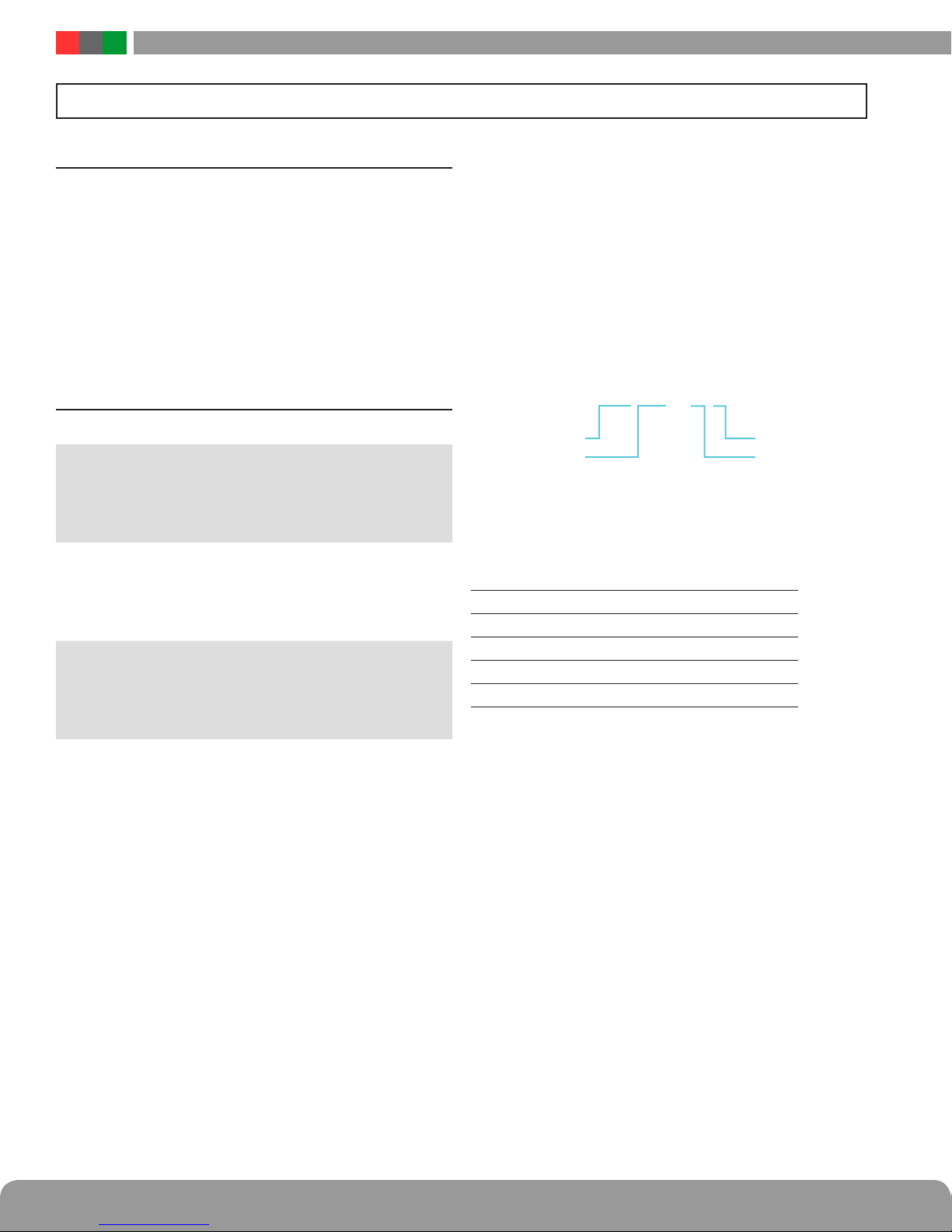
Symbol Definitions
The following symbols are used throughout this manual
This symbol is intended to alert the installer of shock
h
i
h
h
i
i
h
i
hazards within the enclosure. Service should only be
performed by qualified service personnel
This symbol is intended to alert the installer of im-
portant information intended to help the installer
avoid personal injury or property damage
Warnings
Installation and service should be performed only by
qualified service personnel and should conform to
all local codes
To reduce the risk of electric shock or fire, do not
expose this equipment to rain or moisture
This equipment shall be installed in a manner which
prevents unintentional operation by employees,
cleaning personnel, or others working in the premises, by falling objects, customers, building vibration, or similar causes
This equipment is not intended for use within the pa-
tient care areas of a Health Care Facility
Replace fuses only with the same type and rating as
indicated in the specifications section of this manual.
To prevent impaired operation, ensure that all wiring
is routed and secured to prevent accidental open or
short circuit conditions
Regulatory Information
The equipment discussed within this manual has been tested to the following standards:
• EN60950 EN55022 CLASS A EN55024
• CSA C22.2 #60950
• CE
FCC Information
NOTE: This equipment has been tested and found to comply
with the limits for a Class A digital device, pursuant to Part
15 of the FCC Rules. These limits are designed to provide
reasonable protection against harmful interference when
the equipment is operated in a commercial environment.
This equipment generates, uses, and can radiate radio frequency energy and, if not installed and used in accordance
with the instruction manual, may cause harmful interference to radio communications. Operation of this equipment
in a residential area is likely to cause harmful interference in
which case the user will be required to correct the interference at his own expense.
Conventions Used Within this Manual
Positional information (e.g. top, bottom, up, down, left,
right, etc.) is referenced with the board or enclosure in the
orientation shown in the illustrations in this manual
The system and any batteries (if used) should be
i
tested at least once per year to ensure proper operation
NPR Installation Manual
Introduction
Product Description
The NPR series of multi-port PoE midspan injectors are
designed to provide power to PoE compatible IP devices
such as IP surveillance cameras, IP phones, door locks, IR
illuminators and other PoE compatible access control edge
devices. The NPR series products provide 32W of power
per port and are compliant with the IEEE 802.3at standard.
The chart below shows the list of models in the NPR product
family:
The NPR Series
NPR Model No. Description Notes
NPR500-16M 16 port
32W per port
540W total
Managed midspan injector
Standard battery charger
NPR250-16M 16 port
32W per port
270W total
Managed midspan injector
Standard battery charger
NPR250-8M 8 port
32W per port
270W total
Managed midspan injector
Standard battery charger
Programmable
port priority
Programmable
port priority
Programmable
port priority
The illustration below shows the model numbering convention of the NPR series using an example model number.
NPR indicates the model series. The number “500” indicates
a total of 500 Watts nominal output power available. Currently, 500W and 250W models are available. The number
“16” indicates the number of ports. Currently, 16 port and
8 port models are available. The letter “M” indicates remote
management, which is present on all models.
The NPR-M is capable of charging battery sets from 4 to 18
amphours utilizing an internal float charger.
NPR 500 – 16 M
Product series
Total output power
Example NPR series model number
Specifications
Input voltage range 100 – 230 VAC
Input frequency 47 – 63 Hz
Max input current (500W model) 9.0 A
Max input current (250W model) 4.5 A
Power factor >0.92
Managed
Port count
iv 1
Installation and Operation
Section 1 – Installation
The following pages cover the installation of the NPR Series rack-mountable PoE power supplies.
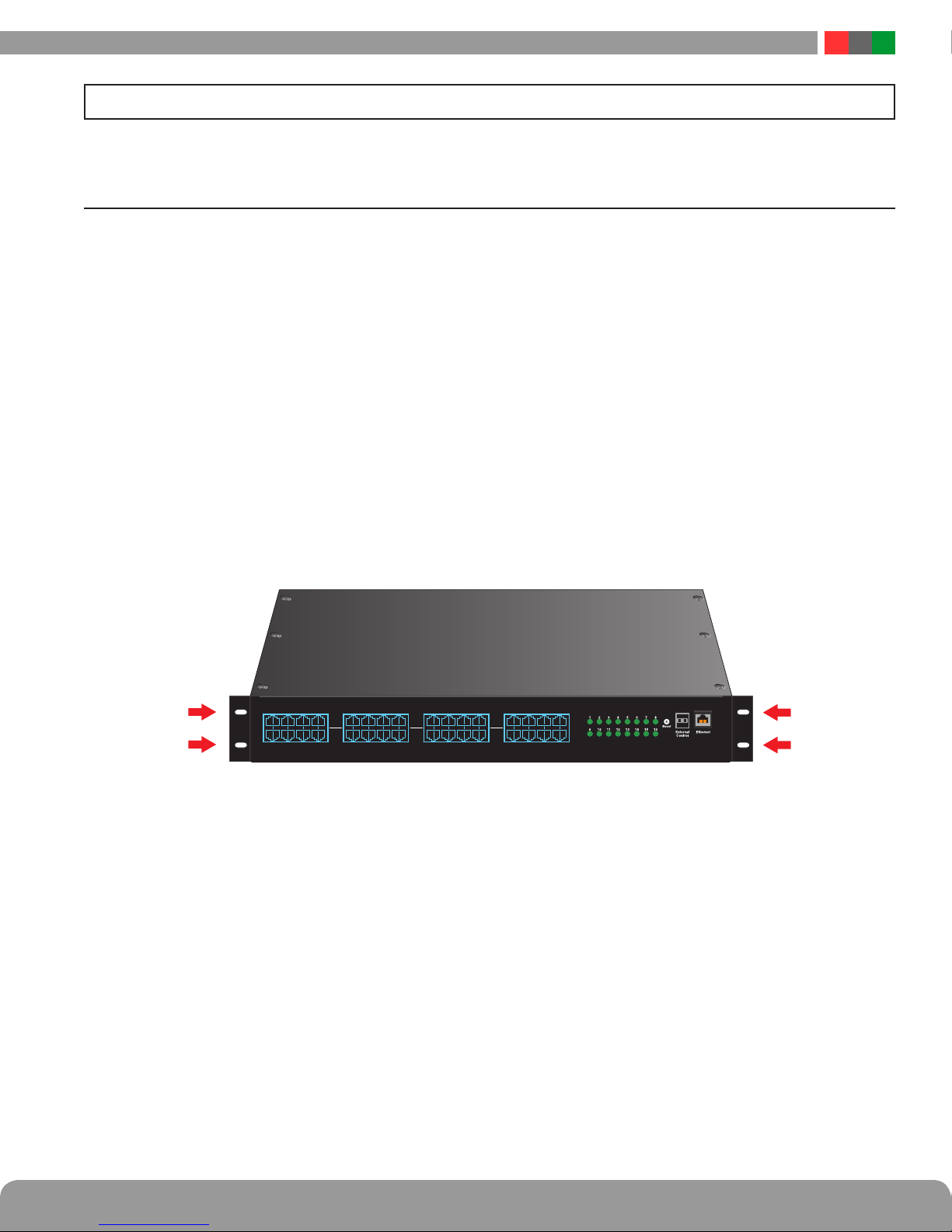
1.1 Mounting the NPR Rack Mount Supply into a Standard 19" Rack
Use the following procedure when mounting an NPR series
supply into a standard EIA 19" equipment rack.
1. If not already, securely mount the included ears to the
front of the enclosure sides using the eight included
countersunk screws (four per ear).
2. Locate the rack-mounting holes in the ears of the enclosure. (Figure 1)
3. Slide the enclosure into an open 1U location in the rack
4. Center the enclosure in the rack and secure with the
four 10-32 x 3/4" screws provided.
NOTE: Use rails or other appropriate support for heavy
enclosures. Keep heavier components near the bottom of
the rack to reduce the risk of toppling of a top-heavy rack.
OUT
1 2 3 4 5 6 7 8 9 10 11 12 13 14 15 16
IN
OUT
IN
OUT
IN
Figure 1: The Enclosure Mounting Holes
NETPOWER
NPR Installation Manual
1.2 NPR Rackmount Power Supply Overview
NETPOWER
h
No user serviceable parts inside
refer servicing to qualified service personnel
Aucune pièce interne ne peut être réparer
Demandez l’assistance d’un technicien qualifié
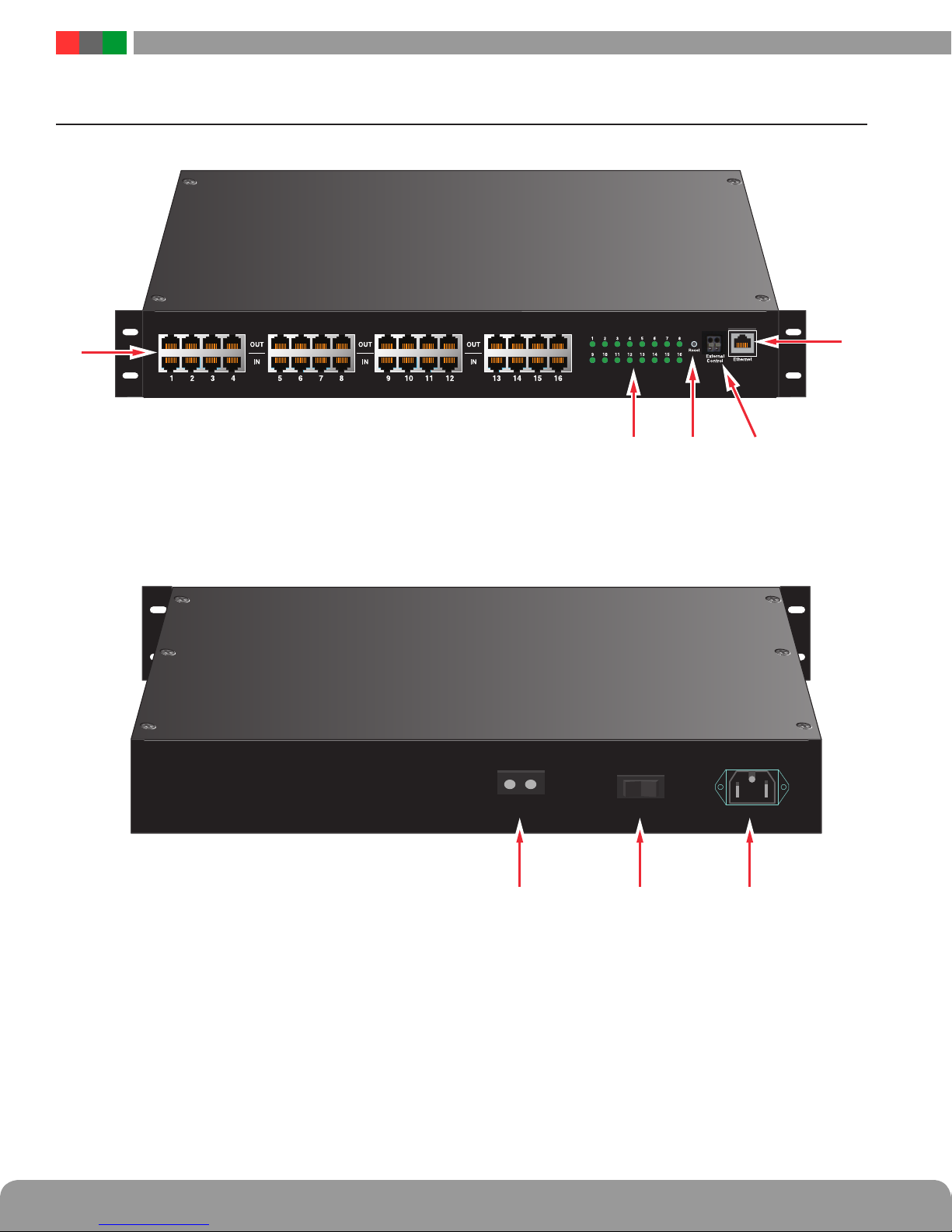
Figure 2: NPR Front View
External DC
Figure 3: NPR Rear View
+–
On / Off
AC Power
2 3

Installation and Operation
The following are basic descriptions. Refer to the appropriate section for more detailed information. Note that the front
panel may appear different based on the configuration of your system.
PoE Input / Output (IN / OUT)
1
Depending on model, there are eight or sixteen RJ45 jack
pairs (top and bottom pair) labeled sequentially. For each
pair, the bottom jack is for network data input. The top jack is
the data and power output.
Connect your data only cables to the bottom row of the RJ45
jacks (from a network switch, video server, etc.).
Connect the top jacks to the corresponding PoE compatible
devices (e.g. IP cameras).
Ethernet Input (Ethernet)
2
This port allows users to monitor and control the NPR multiport midspan injector through a computer, over a LAN or the
Internet. The management software PowerComPoE is web
browser based. You may connect a PC directly to this Ethernet port, or via LAN/Internet.
External Control (External Control)
3
This connector allows an external trigger voltage to shutdown selected PoE outputs (programmed by user via the
PowerComPoE management software).
The trigger voltage is 5 to 24V, AC or DC.
Reset Button (Reset)
4
Pressing the recessed reset button with a pin for 6 seconds
will reset the IP address and password to the factory default
values.
The factory default IP address is: 192.168.1.9
The factory default user name is: admin
Tthe factory default password is: admin
AC Line Input (AC Power)
6
This is the connector for the AC line cord. Plug the included
computer-style line cord into this connector. Connect the
other end of the cord to the power strip inside the rack or another suitable AC power receptacle. The NPR series accepts
120-230VAC ONLY.
Main AC Power Switch / Circuit Breaker (On/Off)
7
This is the main AC power switch for the NPR. This switch
lights when power is on and also has a built-in circuit breaker
rated at 15A. If the circuit breaker trips, reset it by cycling the
switch to off then back to on.
External DC Voltage Input (External DC +/-)
8
This input may be used to either power the NPR via an external 50VDC supply or to provide battery backup to the NPR.
The “External DC” input is reverse polarity protected. See below for details:
To Use Battery Backup
Connect AC power to the NPR unit as normal. In addition,
connect a 48V nominal battery set to the “External DC” connector, using the battery cable supplied.
To Use an External 50Vdc Supply
Connect a 50V power supply to the “External DC” connector
at the rear. The ratings requirements for the DC power supply
are given below:
Input voltage range 44 –57 VDC
Max input current (500W model) 14.0 A
Max input current (250W model) 7.0 A
Front Panel LEDs (1-8 or 1-16)
5
Depending on model, 8 or 16 front panel LEDs (labeled 1
through 8 or 1 through 16) indicate the port status of the
corresponding PoE channels. When the output is connected
to a valid PoE Powered Device (PD) within the specified current limit, the LED will be green, indicating normal operation.
When there is a fault condition, such as when no PD is connected to that port, the LED will be yellow.
The LED will be turned off if the corresponding port is disabled by the PowerComPoE software.
LED Status Status
Green Normal Operation
Yellow (Fault)
Off Port disabled
When the NPR is first powered, these LEDs will light yellow in
sequence (1-8 or 1-16 depending on model) six times as the
unit performs a self-test
No Powered Device connected or fault
condition present
Note that if both AC and DC power sources are connected to
the unit at the same time, the AC source will supply the power
to the output ports. The external DC source will not supply the
outputs unless the AC source is missing or the power switch is
turned off.
 Loading...