

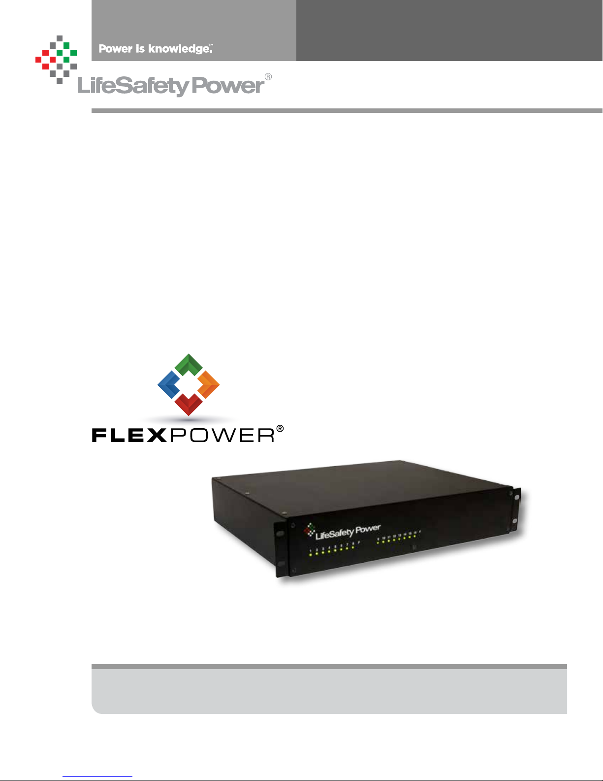
LifeSafety Power Helix RH150 Series, Helix RH75 Series, Helix RH250 Series, Helix RH75-XN, Helix RH150-XN Installation Manual
...
RH Rackmount Installation Manual
LifeSafety Power, Inc. | PH 888.577.2898 | TechSupport@LifeSafetyPower.com
P03-051 Rev A01

RH Series Rackmount Helix Installation Manual
Table of Contents
Notes and Warnings ......................................iii
Symbol Definitions ............................................................ iii
Warnings.................................................................... iii
Regulatory Information ......................................................... iii
Conventions Used Within this Manual.............................................. iii
Introduction............................................iv
Section 1 – Installation ....................................1
1.1 Mounting the Rack Mount Supply into a Standard 19" Rack ...........................1
1.2 HELIX RH Rackmount Field Wiring Connections....................................2
1.2 HELIX RH Rackmount Field Wiring Connections....................................4
1.2 HELIX RH Rackmount Field Wiring Connections - continued ..........................5
1.3 Internal Pre-Configuration.....................................................6
1.4 Making the Wiring Connections.................................................8
Section 2 – Configuration and Usage........................... 9
2.1 Removing the Faceplate of the Enclosure.........................................9
2.2 Disabling Faults ............................................................9
2.3 Status LEDs ...............................................................9
2.4 Remote Access via Ethernet ..................................................10
2.5 HELIX Audible Alarms .......................................................10
Section 3 – Specifications ................................. 11
3.1 Electrical Specifications .....................................................11
i
The Helix RH rackmount series is factory preconfigured for
either 120VAC or 230VAC - verify the proper AC Input voltage
for the model being installed
ii iii

Notes and Warnings
Symbol Definitions
The following symbols are used throughout this manual
This symbol is intended to alert the installer of shock
h
i
h
h
i
i
hazards within the enclosure. Service should only be
performed by qualified service personnel
This symbol is intended to alert the installer of im-
portant information intended to help the installer
avoid personal injury or property damage
Warnings
Installation and service should be performed only by
qualified service personnel and should conform to
all local codes
To reduce the risk of electric shock or fire, do not
expose this equipment to rain or moisture
This equipment shall be installed in a manner which
prevents unintentional operation by employees,
cleaning personnel, or others working in the premises, by falling objects, customers, building vibration, or similar causes
This equipment is not intended for use within the pa-
tient care areas of a Health Care Facility
Regulatory Information
The equipment discussed within this manual has been tested to the following standards:
• UL294, UL603, UL864, UL1076, UL1481,
UL2044, UL2572
• ULC S318, ULC S319, ULC S527
• CSA C22.2 #107.1, CSA C22.2 #60950
FCC Information
Note: This equipment has been tested and found to comply
with the limits for a Class A digital device, pursuant to Part
15 of the FCC Rules. These limits are designed to provide
reasonable protection against harmful interference when
the equipment is operated in a commercial environment.
This equipment generates, uses, and can radiate radio frequency energy and, if not installed and used in accordance
with the instruction manual, may cause harmful interference to radio communications. Operation of this equipment
in a residential area is likely to cause harmful interference in
which case the user will be required to correct the interference at his own expense
Replace fuses only with the same type and rating as
h
i
i
indicated in the specifications section of this manual.
To prevent impaired operation, ensure that all wiring
is routed and secured to prevent accidental open or
short circuit conditions
The system and any batteries (if used) should be
tested at least once per year to ensure proper operation
Conventions Used Within this Manual
Positional information (e.g. top, bottom, up, down, left,
right, etc.) is referenced with the board or enclosure in the
orientation shown in the illustrations in this manual

RH Series Rackmount Helix Installation Manual
Introduction
Product Description
The LifeSafety Power Helix RH rackmount power supplies are
a re dundant power source for use in the Access Control industry. Two identical FPO power supplies are combined in a single
enclosure with the Helix module to provide a single output
voltage. In the event of a failure of the main power source, the
Helix module will automatically switch the output to the backup FPO power supply. Designed to fit neatly into standard 19"
Limitations
i Due to the nature of this product and its intended ap-
plications, the limitations and conditions of installation of
the Helix power supply must be fully understood by the system planner & installer. Please thoroughly read and understand the following sections before using the Helix power
supply.
Redundancy
The Helix RH series of power supplies adds a layer of redundancy over the typical FPO power supply. Only the FPO power
supply is redundant - any distribution in the system is not redundant. Also, the Helix cannot overcome any problems in the
field wiring or load devices - if a short circuit shuts down the
main supply, the backup supply will also be shut down by this
short circuit.
equipment racks, the streamlined cabinetry and exceptional
features combine to significantly reduce installation and service costs. Features include removable terminal strips for field
wiring, input and output surge suppression, automotive blade
fuses for improved reliability, a front removable chassis face
plate for serviceability and is enclosed in a 16 gauge steel 2U
rack mount chassis.
Primary AC Connection
Both FPO power supplies must be powered from the same AC
branch circuit. Powering the two internal FPO power supplies
from different branch circuits could lead to possible improper
operation and loss of output voltage.
Backup Battery
FPO2 must have battery backup connected for proper operation. A battery should not be connected to FPO1 - this is to
prevent cycling between FPO1 and FPO2 during battery discharge on loss of AC.
Fault Contacts
The fault contacts of BOTH FPO power supplies must be monitored to annunciate failure of either power supply. The fault
contacts may either be monitored separately or series/paralleled as needed for a common fault indication. Use of a Netlink
network monitoring module is also highly recommended.
HELIX RH Series
The Helix RH Series of single voltage DC power supplies provide 12 or 24 VDC power at 75W, 150W and 250W of total
power. They are available with 8 or 16 outputs and the capability of remote monitoring of the supply's parameters via internet
or intranet connection. Ideal for Access Control, CCTV, Burglar,
Fire, or Mass Notification applications. Helix provides added
DC Product Power Outputs Description
RH75 Series 75W 2 Single Voltage 6A @ 12VDC or 3A @ 24VDC / dual output
RH150 Series 150W 2 Single Voltage 12A @ 12VDC or 6A @ 24VDC / dual output
RH250 Series 250W 2 Single Voltage 20A @ 12VDC or 10A @ 24VDC / dual output
Remote monitoring
RH75-XN 75W 8, 16 Single Voltage / Network 6A @ 12VDC or 3A @ 24VDC / multiple outputs / network
RH150-XN 150W 8, 16 Single Voltage / Network 12A @ 12VDC or 6A @ 24VDC / multiple outputs / network
RH250-XN 250W 8, 16 Single Voltage / Network 20A @ 12VDC or 10A @ 24VDC / multiple outputs / network
system integrity by automatically switching to the backup
power supply in the event of a problem with the primary power
supply. Each output is fused at 3A, but may be increased up to
7.5A by the installer for powering high power devices.
iv 1
Installation and Operation
Section 1 – Installation
The following pages cover the installation of the Helix RH Series rack-mountable power supplies.
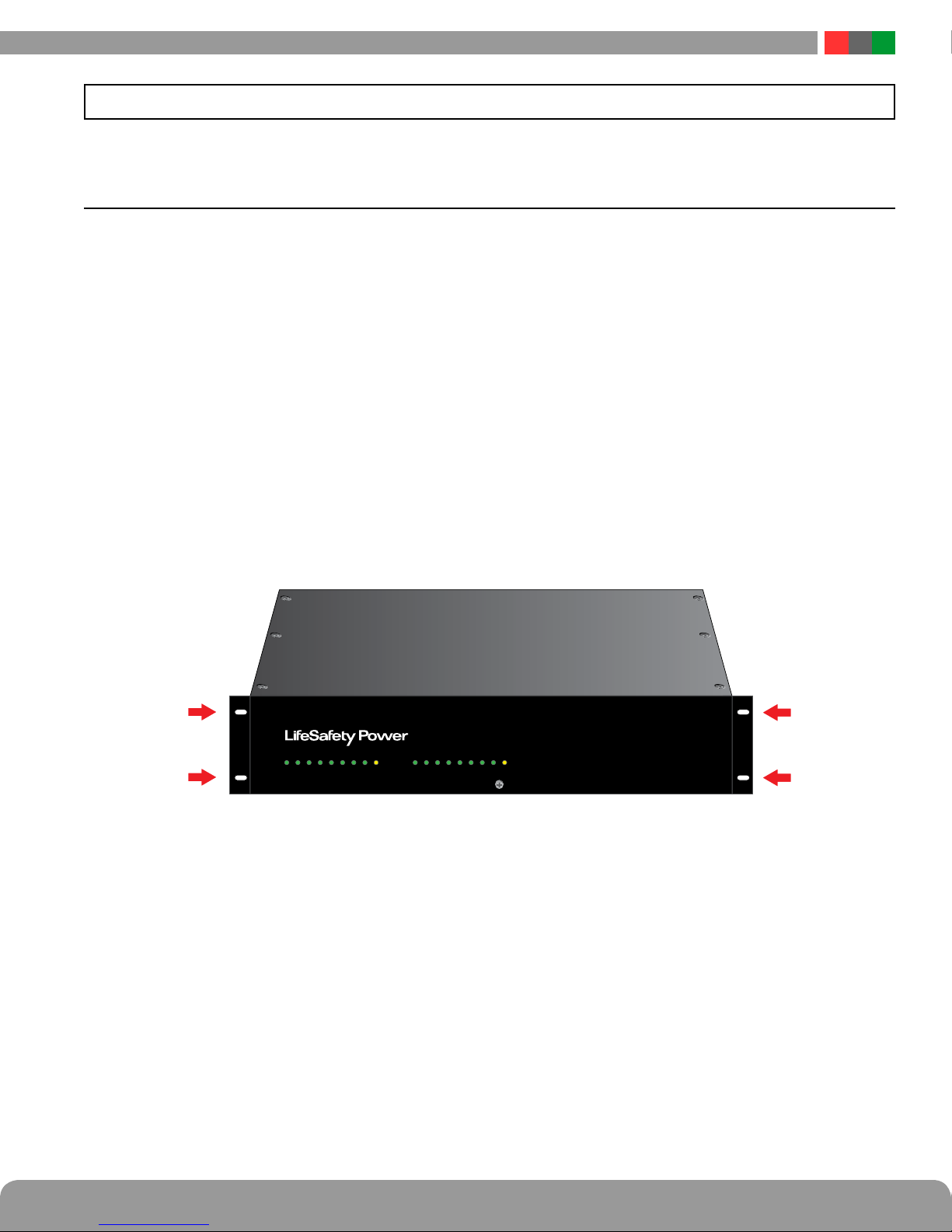
1.1 Mounting the Rack Mount Supply into a Standard 19" Rack
Use the following procedure when mounting an RH series
supply into a standard EIA 19" equipment rack.
1. Ensure any internal configuration (voltage selection, fault
detection settings, etc) are complete before mounting.
See Section 1.3 of this manual for more information.
2. Securely mount the included ears to the enclosure sides
using the eight included 6-32 countersunk screws (four
per ear).
3. Locate the rack-mounting holes in the ears of the enclosure. (Figure 1)
4. Slide the enclosure into an open 2U location in the rack
5. Center the enclosure in the rack and secure with the
four 10-32 x 3/4" screws provided.
NOTE: Use rails or other appropriate support for heavy
enclosures. Keep heavier components near the bottom of
the rack to reduce the risk of toppling of a top-heavy rack.
2 3 4 5 6 7 8 F F1 10 11 12 13 14 15 169
Figure 1 - The Enclosure Mounting Holes
i
The Helix RH rackmount series is factory preconfigured
for either 120VAC or 230VAC - verify the proper AC Input
voltage for the model being installed
 Loading...