

LifeSafety Power FlexPower Vantage FPV4-R8PE1, FlexPower Vantage FPV6-R8E1, FlexPower Vantage R8 series, FlexPower Vantage FPV4-R8E1, FlexPower Vantage FPV6-R8PE1 Installation Manual
...
Smart Power Supply Chargers
R8 Access Power
Installation Guide
FPV4-R8E1
4 amp @ 12VDC or 3A/24VDC
Eight (8) Fused outputs
FPV6-R8E1
6 amp @ 12VDC or 24VDC
Eight (8) Fused outputs
FPV102-R8E1
10 amp @ 12VDC
Eight (8) Fused outputs
FPV104-R8E1
10 amp @ 24VDC
Eight (8) Fused outputs
For 230VAC input add "/E" to model number - example FPV6-R8E1/E
For larger enclosure change E1 sux to E2 in model number - example FPV6-R8E2
FPV4-R8PE1
4 amp @ 12VDC or 3A/24VDC
Eight (8) Class II Power Limited outputs
FPV6-R8PE1
6 amp @ 12VDC or 24VDC
Eight (8) Class II Power Limited outputs
FPV102-R8PE1
10 amp @ 12VDC
Eight (8) Class II Power Limited outputs
FPV104-R8PE1
10 amp @ 24VDC
Eight (8) Class II Power Limited outputs
TechSupport@LifeSafetyPower.com
LifeSafety Power, Inc.
PH 888.577.2898
P03-054

FlexPower Vantage R8 Access Power System - Installation Manual 2
Symbol Definitions
The following symbols are used throughout this manual:
This symbol is intended to alert the installer of shock
h
hazards within the enclosure. Service should only be
performed by qualified service personnel.
This symbol is intended to alert the installer of important
i
information intended to help the installer avoid personal
injury or property damage.
Warnings
Installation and service should be performed only by quali-
h
fied service personnel and should conform to all local codes.
To reduce the risk of electric shock or fire, do not
h
expose this equipment to rain or moisture.
This equipment shall be installed in a manner which
i
prevents unintentional operation by employees,
cleaning personnel, or others working in the premises, by falling objects, customers, building vibration,
or similar causes.
This equipment is not intended for use within the patient
i
care areas of a Health Care Facility.
Replace fuses only with the same type and rating as
h
indicated in the specifications section of this manual.
Batteries (if used) should be maintained at an ambient tem-
i
perature of between 32 and 120 degrees Fahrenheit (0-49
Celsius) or premature loss of battery power could occur.
Test and verify output voltage before connecting the
i
load.
R
The equipment discussed within this manual has been
tested to the following standards:
• UL294, UL603, UL1076
• ULC S318, ULC S319
• CSA C22.2 #107.1
FCC Information
Note: This equipment has been tested and found to com-
ply with the limits for a Class A digital device, pursuant to
Part 15 of the FCC Rules and ICES-003. These limits are
designed to provide reasonable protection against harmful interference when the equipment is operated in a commercial environment. This equipment generates, uses, and
can radiate radio frequency energy and, if not installed and
used in accordance with the instruction manual, may cause
harmful interference to radio communications. Operation of
this equipment in a residential area is likely to cause harmful interference in which case the user will be required to
correct the interference at his own expense.
To prevent impaired operation, ensure that all wiring is
i
routed and secured to prevent accidental open or short
circuit conditions.
The system and any batteries (if used) should be tested
i
at least once per year to ensure proper operation.
Enclosure Mounting
Mounting an Enclosure
Use the following procedure when mounting a wall-mount enclosure.
1. (Optional) Remove the enclosure’s cover.
2. Locate the top keyhole mounting holes in the back of the enclosure.
3. Mark and pre-drill the locations for the keyholes in the
mounting surface.
4. Partially install two fasteners appropriate for the surface on which the enclosure is being installed. Leave the
heads of the fasteners approximately ¼" out from the
surface. Minimum fastener size should be #10 or larger.
5. Hang the enclosure on the two fasteners and mark the
locations of the remaining mounting holes.
6. Remove the enclosure and pre-drill the locations for the
remaining mounting holes.
7. Re-hang the enclosure on the top mounting fasteners,
start the remaining fasteners and tighten all fasteners.
8. Reinstall the enclosure’s cover, if removed in step 1.
Conventions Used Within this Manual
Positional information (e.g. top, bottom, up, down, left,
right, etc.) is referenced with the board or enclosure in the
orientation shown in the illustrations in this manual.
i It is the installer’s responsibility to determine the
appropriate fastening system for use with the surface the enclosure is being mounted to.
i For UL1076 applications, after installation is com-
plete, the installer must install the two supplied 1"
long screws to the edge of the enclosure's cover
for additional security.
FPV4
FPV6, 102,
104
FlexPower Vantage R8 Access Power System - Installation Manua 3
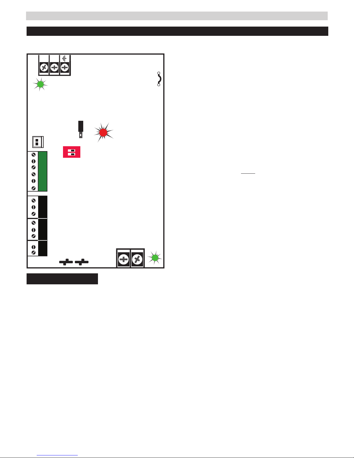
FPV4 Power Supply Overview -
This guide gives the basic information needed to install a system containing a single Vantage Power Supply for most applications.
N
L
AC ON
Voltage Select
12V
24V
ON
FAI and Charge
Current settings
FAI
FlexIO
FAI INPUTFAI INPUT
1 2
SYS FLTSYS FLT
I
Read before Power Up
1
AC Select
cut jumper for
230VAC
Leave INTACT for 120V input. CUT for 230V input.
I Failure to cut this jumper when using the FPV with a 230VAC
2
3
4
I Remove AC input power before changing the voltage select switch
5
AC Voltage Select Jumper - -
input will result in damage to the system and void the warranty.
AC Input primary AC connection.
AC LED (GREEN) indicates a valid AC input voltage is pres-
ent. Missing AC is indicated by this LED extinguishing.
H Always confirm the absence of AC power with a meter
before servicing to prevent electric shock.
Voltage Selection Jumper selects the output voltage
between 12V and 24V DC.
to avoid damaging the power supply or connected equipment.
FAI LED (RED) indicates activation of the Fire Alarm Input.
IFor FAI wiring see page 9.
FPV4
DC ON
Flex IO Connector Supplies FAI status to any accessory
6
boards. Receives fault signal from accessory boards.
FAI and Charge Current Configuration Switches
7
Switch 1 - FAI Selection
Off = Constant Output
On = Output switches on FAI
AC FLTAC FLT AUXAUX
Observe
Observe
battery polarity
battery polarity
or damage may result
or damage may result
–
i
+
ALWAYS DISCONNECT POWER BEFORE CHANGING
OUTPUT VOLTAGE TO PREVENT PS DAMAGE
I
Auxiliary Voltage is a fixed Class 2 DC output.
bl
Battery Terminal Connection for the optional
bm
battery backup. Battery set voltage must match
the DC output voltage setting.
Main DC Output of the power supply. The output
bn
can either be constant or switched based on the
configuration setting of switch.
• The DC ON LED will be green with voltage present.
Switch 2 - Charge Current
Off = High Charge Current
On = Low Charge Current
FAI Input The input from the FACP. Can be wired to accept
8
a NO, NC, Open Collector, or Voltage input.
See page 6 for FAI wiring information.
System Fault Contact - Contact labeling is adjacent to the
9
terminals and shown in the unpowered (FAULT) condition.
AC Fault Contact Contact labeling is adjacent to the
bk
terminals and shown in the unpowered (FAULT) condition.
AC fault is indicated on a missing AC Input voltage.
I For FPV6, FPV102, FPV104 - see page 4
FlexPower Vantage R8 Access Power System - Installation Manual 4
Observe battery polarity
or damage may result
Observe battery polarity
or damage may result
i
+
–
ON
1 2
For UL compliance, the AC fault contact
must be monitored by a listed control panel
N
L
FPV4
AC INPUT
AC Select
cut jumper for
230VAC
FlexIO
AC ON
DC ON
FAI and Charge
Current settings
12V 24V
SYS FLTSYS FLT
AC FLTAC FLT AUXAUX
FAI INPUTFAI INPUT
FAI
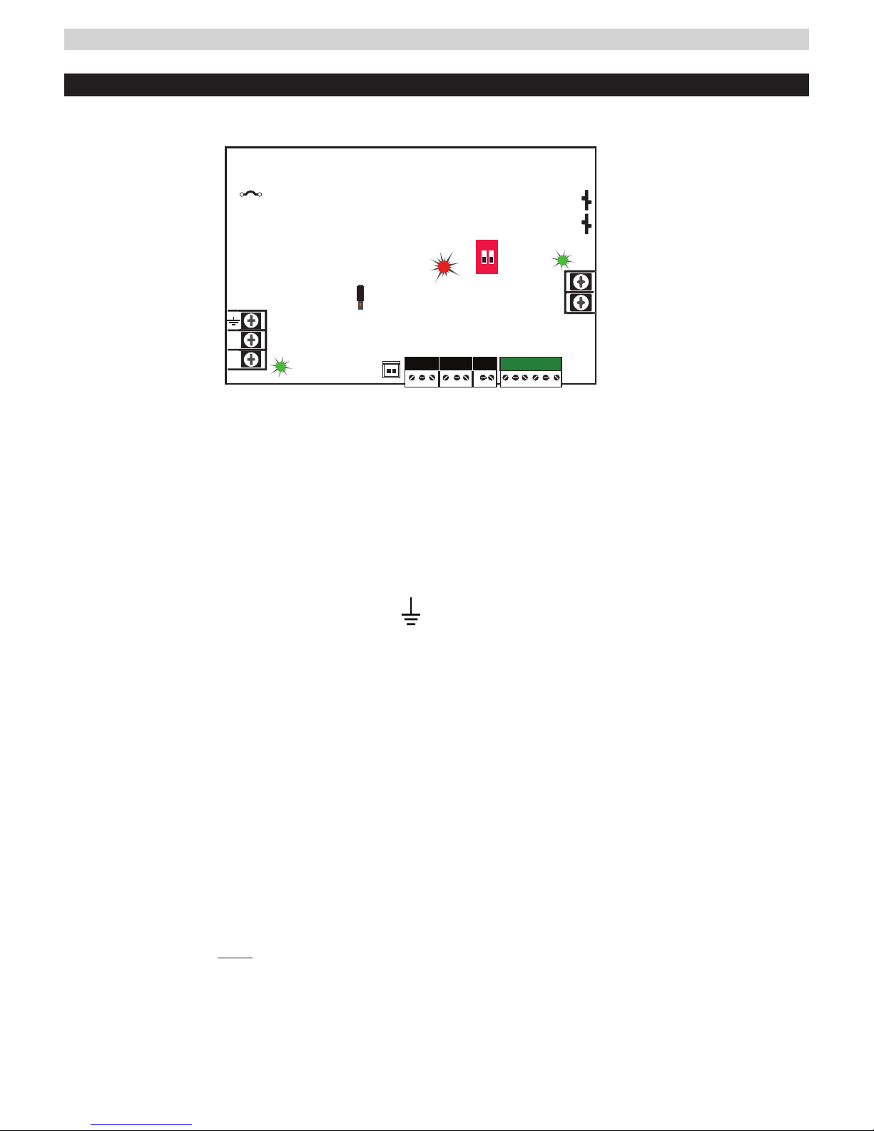
FPV6, 102, 104 Power Supply Overview -
I
Read before Power Up
This guide gives the basic information needed to install a system containing a single Vantage Power Supply for most applications.
AC Select
cut jumper for
230VAC
AC INPUT
N
L
AC Input Voltage Selection
1
Leave INTACT for 120V input. CUT for 230V input (models
ending in "/E" have jumper precut for 230VAC input).
I Failure to cut this jumper when using FPV power sup-
ply with a 230VAC input will result in damage to the system
FPV6 12/24V @ 6A
FPV102 12V @ 10A
FPV104 24V @ 10A
AC ON
12/24VDC jumper
on FPV6 only
preset to 12V
FlexIO
SYS FLTSYS FLT
For UL compliance, the AC fault contact
must be monitored by a listed control panel
+
FAI and Charge
Current settings
ON
1 2
1
AC FLTAC FLT AUXAUX
6
2
FAI INPUTFAI INPUT
Charge Current / Main output FAI Configuration Switches
Switch 1 - FAI Selection I Switch must remain Off.
FAI selection made on R8 board - page 9.
–
DC ON
Switch 2 - Charge Current
Off = High Charge Current | On = Low Charge Current
and void the warranty.
FLEX IO Connector
7
AC Input Terminal Block
2
The primary AC connection. Connect Hot Line to terminal
Supplies FAI status to any accessory boards. Receives fault
signal from accessory boards.
"L", neutral to terminal "N" and earth ground to terminal
System Fault Contact
For 230VAC input cut JP1 Jumper (see #1 above).
8
The System Fault contact output. Contact labeling is ad-
I Models ending in "/E" are factory pre-set for 230VAC input.
AC ON LED (green)
3
Indicates a valid AC input voltage is present. Missing AC is
indicated by this LED extinguishing.
H Always confirm the absence of AC power with a meter
before servicing to prevent electric shock.
jacent to the terminals. When at fault, the NO-C contact is
open, NC-C contact is closed (relay not energized).
AC Fault Contact
9
The AC Fault contact output. Contact labeling is adjacent to
the terminals. When AC is lost, the NO-C contact is open,
NC-C contact is closed (relay not energized).
FAI LED (red)
4
Indicates activation of the Fire Alarm Input.
12/24V Selection Jumper (model FPV6 only)
5
This selects the output voltage between 12V and 24V DC
on FPV6 models. The FPV power supply must be completely powered down before changing this setting. Voltage markings are printed on the PC Board adjacent to the
selector.
I Remove AC input power before changing the voltage select
jumper to avoid damaging the power supply or connected equipment.
I Models FPV102 and FPV104 are a fixed output voltage:
FPV102: 12V / 10 Amps
FPV104: 24V / 10 Amps
AUX Output
bk
The auxiliary voltage is fixed Class 2 Power Limited DC output.
FAI Input
bl
The input from the FACP. Can be wired to accept a NO, NC,
Open Collector, or Voltage input.
See page 6 for FAI wiring information.
Main Output
bm
This is the main DC output of the power supply.
Battery Terminal Connection
bn
The connection for the optional backup battery. Battery set
voltage must match the DC output voltage setting.
FlexPower Vantage R8 Access Power System - Installation Manua 5
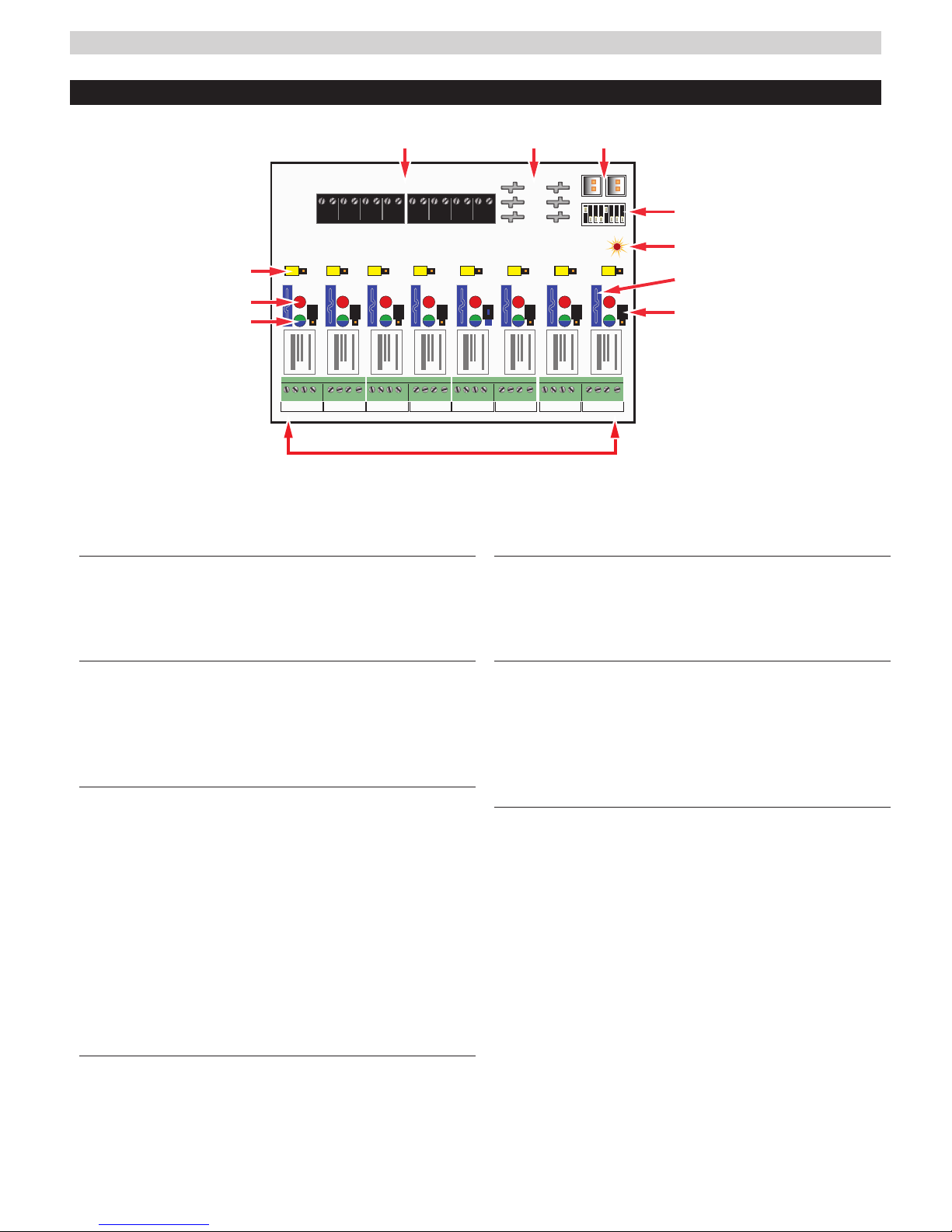
R8 Power Control Accessory Module Overview
INPUT 1 - 4 INPUT 5 - 8
GND GND GND GND
GND GND GND GND
1 2 3 4
1 2 3 4
B1 B2 B1 B2 B1 B2 B1 B2 B1 B2 B1 B2 B1 B2 B1 B2
5 6 7 8
5 6 7 8
NC C N0 COM NC C N0 COM
OUTPUT 1 OUTPUT 2
NC C N0 COM NC C N0 COM
OUTPUT 3 OUTPUT 4
I The relay contact outputs have suppression diodes across them. For a dry contact output, the output
diodes must be cut and the yellow and black jumpers removed.
FlexIO Connectors
1
These connectors pass the FAI signal to the R8/R8P
board and pass the FlexIO buss on to other accessory
boards in the system.
GND GND GND GND
GND GND GND GND
NC C N0 COM NC C N0 COM
OUTPUT 5 OUTPUT 6
B1
B2
BR
1
FAI
8
NC C N0 COM NC C N0 COM
OUTPUT 7 OUTPUT 8
Relay State LEDs (Red)
5
These LEDs indicate the state of the output relay.
The LED will be lit when the relay is active and extinguished when the relay is not active.
B1, B2, and BR Connectors
2
These connectors are the voltage inputs for the R8/R8P board.
BR is the DC Common buss in the system. B1 is the positive
voltage input for the first power supply. In dual voltage systems, B2 is the input for the second power supply.
Zone Inputs (IN1 – IN8)
3
These are the zone input terminal strips. These terminal
strips are removable and accept wire sizes from AWG14
– AWG22. The terminals are labeled on the PC board
near the terminal strip. See the Input Wiring section of
this manual for more information.
• When using a normally open relay contact input, the
contact is connected across the IN and GND terminals.
• When using an open collector (transistor) input, the
open collector it connected to the IN terminal. Note
that the input source must be common grounded
with the
Voltage Selection Jumpers (Yellow)
4
R8/R8P
board’s power source.
These jumpers select the power input to be used for
each output. For single voltage systems, this jumper
should stay in the B1 position. this jumper should be
removed on any zones where a dry contact output is
needed.
Output Voltage LEDs (Dual Color - Blue/Green)
6
These LEDs indicate the voltage of the zone’s output.
• BlueThe output is set to 24V
• GreenThe output is set to 12V
• OffFuse or PTC open or dry contact output se-
lected
Zone Outputs (01 – 08)
7
These are the zone output terminal strips. These terminal strips are removable and accept wire sizes from
AWG14 – AWG22. The terminals are labeled on the PC
board near the terminal strip. See the Output Wiring
section for more information.
• C, NC, and NO are the relay output.
– The C terminal will always have voltage present
when the yellow jumper is installed, regardless of
relay state.
– NC will have voltage when the relay is NOT ACTIVE. Use for Fail Safe locks.
– NO will have voltage when the relay is ACTIVE.
Use for Fail Secure locks.
• COM is the DC common terminal for the output
I CAUTION When powering magnetic loads such as
maglocks, door strikes, solenoids, etc, each of these
loads must have a reverse protection diode either built-
 Loading...