

LifeSafety Power FLEXPOWER RC250 Series, FLEXPOWER RC75B Series, FLEXPOWER RC250B Series, FLEXPOWER RC150 Series, FLEXPOWER RC150B Series Installation Manual

RC Rackmount Installation Manual
LifeSafety Power, Inc. | PH 888.577.2898 | TechSupport@LifeSafetyPower.com
P03-050 Rev A03

RC Series Rackmount Installation Manual
Table of Contents
Notes and Warnings ......................................iii
Symbol Definitions ............................................................ iii
Warnings.................................................................... iii
Regulatory Information ......................................................... iii
Conventions Used Within this Manual.............................................. iii
Introduction............................................iv
Section 1 – Installation & Operation ...........................1
1.1 Mounting the Rackmount Supply into a Standard 19" Rack ...........................1
1.2 RC Series Rackmount Power Supply Overview .....................................2
1.3 Internal Pre-Configuration.....................................................4
1.4 Making the Wiring Connections.................................................6
Section 2 – Configuration and Usage........................... 9
2.1 Removing the Faceplate of the Enclosure.........................................9
2.2 Configuring the Zones .......................................................9
2.3 Status LEDs ..............................................................10
2.4 Remote Access via Ethernet ..................................................10
Section 3 – Electrical Specifications .......................... 12
3.1 Electrical Specifications ......................................................1
ii iii

Notes and Warnings
Symbol Definitions
The following symbols are used throughout this manual
This symbol is intended to alert the installer of shock
h
i
h
h
i
i
h
i
hazards within the enclosure. Service should only be
performed by qualified service personnel
This symbol is intended to alert the installer of im-
portant information intended to help the installer
avoid personal injury or property damage
Warnings
Installation and service should be performed only by
qualified service personnel and should conform to
all local codes
To reduce the risk of electric shock or fire, do not
expose this equipment to rain or moisture
This equipment shall be installed in a manner which
prevents unintentional operation by employees,
cleaning personnel, or others working in the premises, by falling objects, customers, building vibration, or similar causes
This equipment is not intended for use within the pa-
tient care areas of a Health Care Facility
Replace fuses only with the same type and rating as
indicated in the specifications section of this manual.
To prevent impaired operation, ensure that all wiring
is routed and secured to prevent accidental open or
short circuit conditions
Regulatory Information
The equipment discussed within this manual has been tested to the following standards:
• UL294, UL864, UL1076, UL2044
• ULC S318, ULC S319, ULC S527
• CSA C22.2 #107.1, CSA C22.2 #60950
FCC Information
Note: This equipment has been tested and found to comply
with the limits for a Class A digital device, pursuant to Part
15 of the FCC Rules. These limits are designed to provide
reasonable protection against harmful interference when
the equipment is operated in a commercial environment.
This equipment generates, uses, and can radiate radio frequency energy and, if not installed and used in accordance
with the instruction manual, may cause harmful interference to radio communications. Operation of this equipment
in a residential area is likely to cause harmful interference in
which case the user will be required to correct the interference at his own expense
Conventions Used Within this Manual
Positional information (e.g. top, bottom, up, down, left,
right, etc.) is referenced with the board or enclosure in the
orientation shown in the illustrations in this manual
The system and any batteries (if used) should be
i
tested at least once per year to ensure proper operation
RC Series Rackmount Installation Manual
Introduction
Product Description
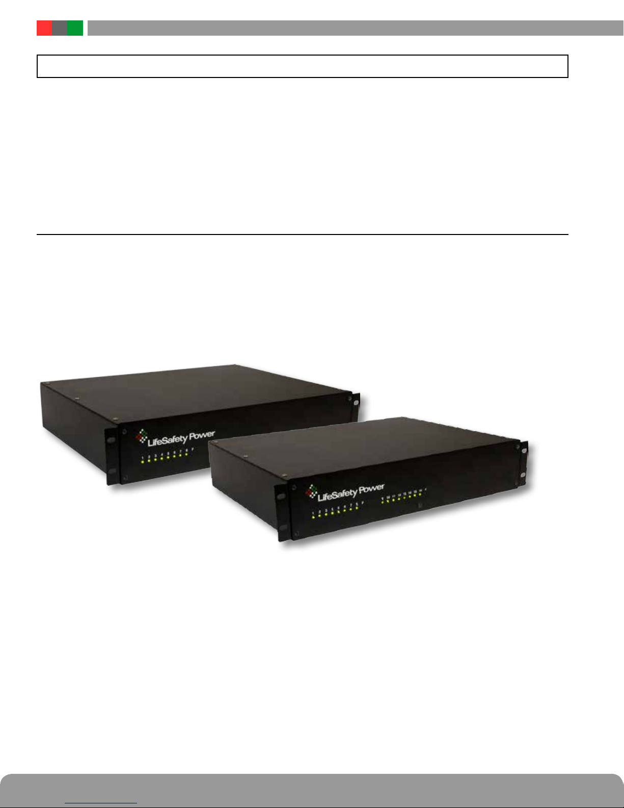
The FLEXPOWER RC Series of power sup plies provide
DC Lock or Camera power for lifesafety applications. Designed to fit neatly into standard 19" equipment racks, the
streamlined cabinetry and exceptional features com bine to
significantly reduce installation and service costs. Features
RC Series
The RC Series provides 12 and/or 24 VDC power at 75W,
150W and 250W of total power. They are available with 8 or
16 outputs and provide lock control for each output, and are
available with optional network monitoring (RC-N models).
include removable terminal strips for field wiring, input and
output surge suppression, automotive blade fus es for improved reliability, a front removable chassis face plate for
serviceability and is enclosed in a 16 gauge steel 2U Rackmount chassis.
Ideal for Access Control, CCTV, Burglar, Fire, or Mass Notification applications. The RC Series delivers flexibility for
large projects by providing increased current capability and
allowing the user to select either 12 VDC or 24 VDC on each
output (dual supply units only).
iv 1
Section 1 – Installation & Operation
The following pages cover the installation of the RC Series power supplies.
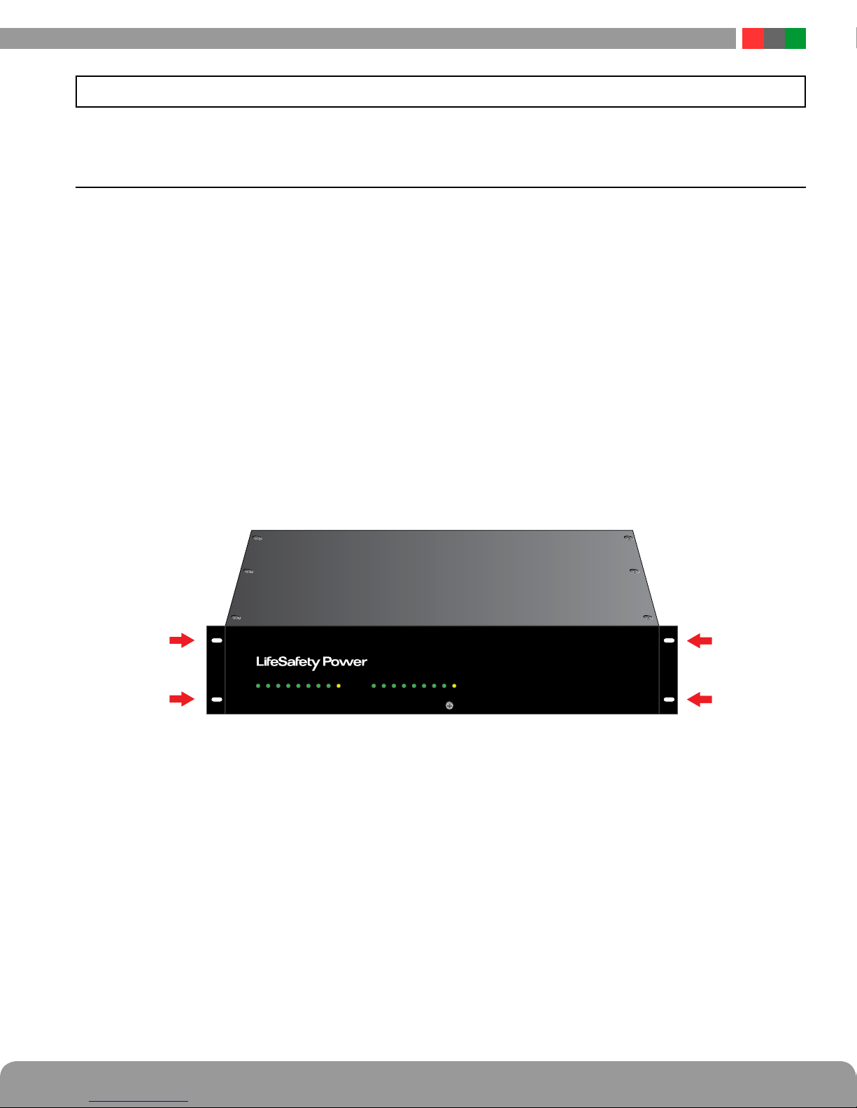
1.1 Mounting the Rackmount Supply into a Standard 19" Rack
Installation and Operation
Use the following procedure when mounting an RC series
supply into a standard EIA 19" equipment rack.
1. Ensure any internal configuration voltage selection and
fault detection settings are complete before mounting.
See Section 1.3 of this manual for more information.
2. Securely mount the included ears to the enclosure sides
using the eight included 6-32 countersunk screws (four
per ear).
3. Locate the rack-mounting holes in the ears of the enclosure. (Figure 1)
4. Slide the enclosure into an open 2U location in the rack
5. Center the enclosure in the rack and secure with the
four 10-32 x 3/4" screws provided.
i Use rails or other appropriate support for heavy en-
closures. Keep heavier components near the bottom of
the rack to reduce the risk of toppling of a top-heavy rack.
i Ensure adequate spacing between the systems for
proper ventilation. If the internal temperature of the rack
is high, a ventilation fan for the rack should be considered.
2 3 4 5 6 7 8 F F1 10 11 12 13 14 15 169
Figure 1 - The Enclosure Mounting Holes
Note: The RC Series is preconfigured for a 120VAC input. See
i
section 1.3.2 to set for a 230VAC input.
RC Series Rackmount Installation Manual
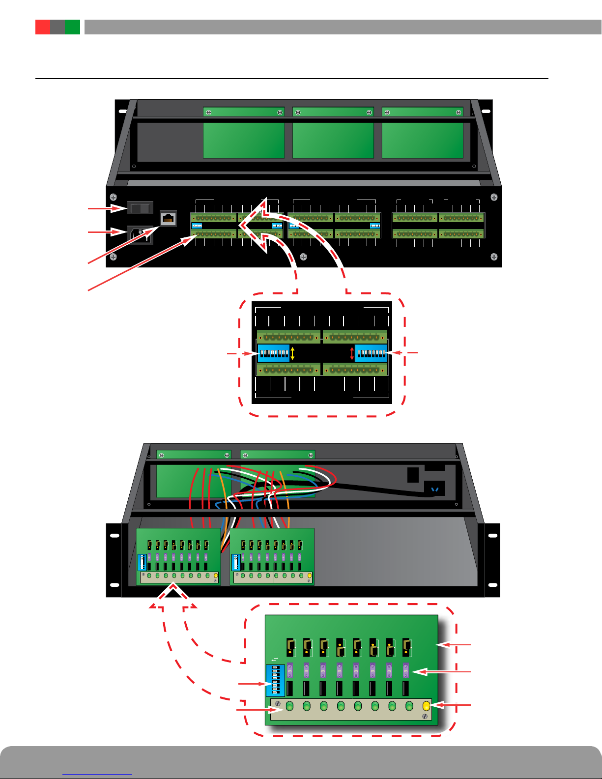
1.2 RC Series Rackmount Power Supply Overview
AC Power
10-100
Base-T
CONTROLLED OUTPUTS 1 CONTROLLED OUTPUTS 2
1
A B2A B3A B4A B
ON ON ON ON
A B10A B11A B12A B13A B14A B15A B16A B
9
5
A B6A B7A B8A B
CONTROL INPUTS 1 CONTROL INPUTS 2
9
A B10A B11A B12A B13A B14A B15A B16A B
A B10A B11A B12A B13A B14A B15A B16A B
9
CONTROLLED OUTPUTS
1 2 3 4 5 6 7 8
-+-+-+-
ON
2
A B
N.O. INPUT
N.C. INPUT
87
3 4 5 6
A B A B A B A B A B A B A B
1+2 3 4
-+-+-+-
Enable FAI
Disable FAI
1ON2
5+6 7 8
CONTROL INPUTS
3 4 5 6
MAIN OUTPUT 2
BAT+
BAT-
DC1 +
DC1 -
DC2 +
I -
V -
I -
I - SFSF
V +
871
MAIN OUTPUT 1
BAT+
BAT-
DC1 +
DC1 -
DC2 +
DC2 -
ACF
DC2 -
ACF
ACF
V -
V +
ACF
I -
V -
I -
V -
I - SFSF
333333333
87
3333333
3 4 5 6
2
1
ON
CH1 CH2 CH3 CH4 CH5 CH6 CH7 CH8
CH1 CH2 CH3 CH4 CH5 CH6 CH7 CH8
333333333
3
87
3 4 5 6
2
1
ON
FLT
FLT
CH1 CH2 CH3 CH4 CH5 CH6 CH7 CH8
CH1 CH2 CH3 CH4 CH5 CH6 CH7 CH8
3333333
OUTPUT
OUTPUT
Fail-Safe
Fail-Secure
87
3 4 5 6
2
1
ON
CH1 CH2 CH3 CH4 CH5 CH6 CH7 CH8
CH1 CH2 CH3
3
FLT
FLT
VOLTAGE SELECT JUMPERS
3—3
3
3
3
3
3
3
CH4 CH5 CH6 CH7 CH8
3
3
3
3
DC1
3
3
3
DC2
3
3
FLT
FLT
2 3
 Loading...