

LifeSafety Power FlexPower N24 Installation Manual

N24 Installation Manual
LifeSafety Power, Inc. | PH 888.577.2898 | TechSupport@LifeSafetyPower.com
P03-027 Rev A08

N24 Installation Manual
DC OUT terminals to devices to be powered
Description
The N24 NAC Expander accessory provides up to four NAC
outputs, controlled by one or two NAC inputs. Inputs and Outputs can be configured as Class A or Class B. Maximum output
is 3A per output zone. The N24 is powered from a 100W or
larger FPO power supply set for 24VDC. The N24 works either
as a follower (passing along synchronization or audible coding) or generates its own synchronization or audible coding.
Electrical Specifications
Power
Input
Zone
Inputs
Zone
Outputs
Voltage 24VDC nominal ±15%
Current 12A maximum
Standby Current 100mA maximum
Alarm Current 250mA max. plus output load
Voltage 24VDC maximum
Current 25mA maximum
Voltage 24VDC
(Regulated 24V DC rating)
Current 3A max per output
Max. line impedance 1.5 Ohms
I Note that the total current draw from any
buss must not exceed the capability of the
power supply powering that buss
Fuse 30A ATM automotive style
Regulatory Information
The equipment discussed within this manual has been tested
to the following standards:
• UL864
• ULC S527
• CSFM Approved
•
Mounting the N24 Power Distribution Module
Mounting of the board to an enclosure is via the four
snap-in standoffs supplied.
1. Locate the appropriate
mounting holes in the
enclosure and snap
the standoffs into the
holes.
2. Align the board mounting holes with the
standoffs (be sure the
PC board is properly oriented) and snap the board onto
the standoffs.
N24 Board
N24
Connecting the N24 Power Distribution Module
Remove all AC and battery power from the FPO system before adding or replacing an N24 module.
h
Each of the B1, B2, BR, and FlexIO busses has two connectors.
Required Connections
Optional Connections
FlexIO in from System
Input from Main
DC voltage source
Input from Second
DC source (optional)
BR in from System
B1
B2
BR
N24 Board
N24
These connectors may be used interchangeably.
For example: FlexIO from the power supply may be connected
to either of the N24's FlexIO connectors, the Main DC voltage
source may connect to either B1 terminal, etc.
FlexIO continues to other accessories
B1
B2
BR
DataLink
FlexIO
1
2
3
4
5
6
7
A B C D A B C D
Main DC voltage continues to
other accessories
Second DC Source continues to
other accessories
BR continues to other accessories
2 3
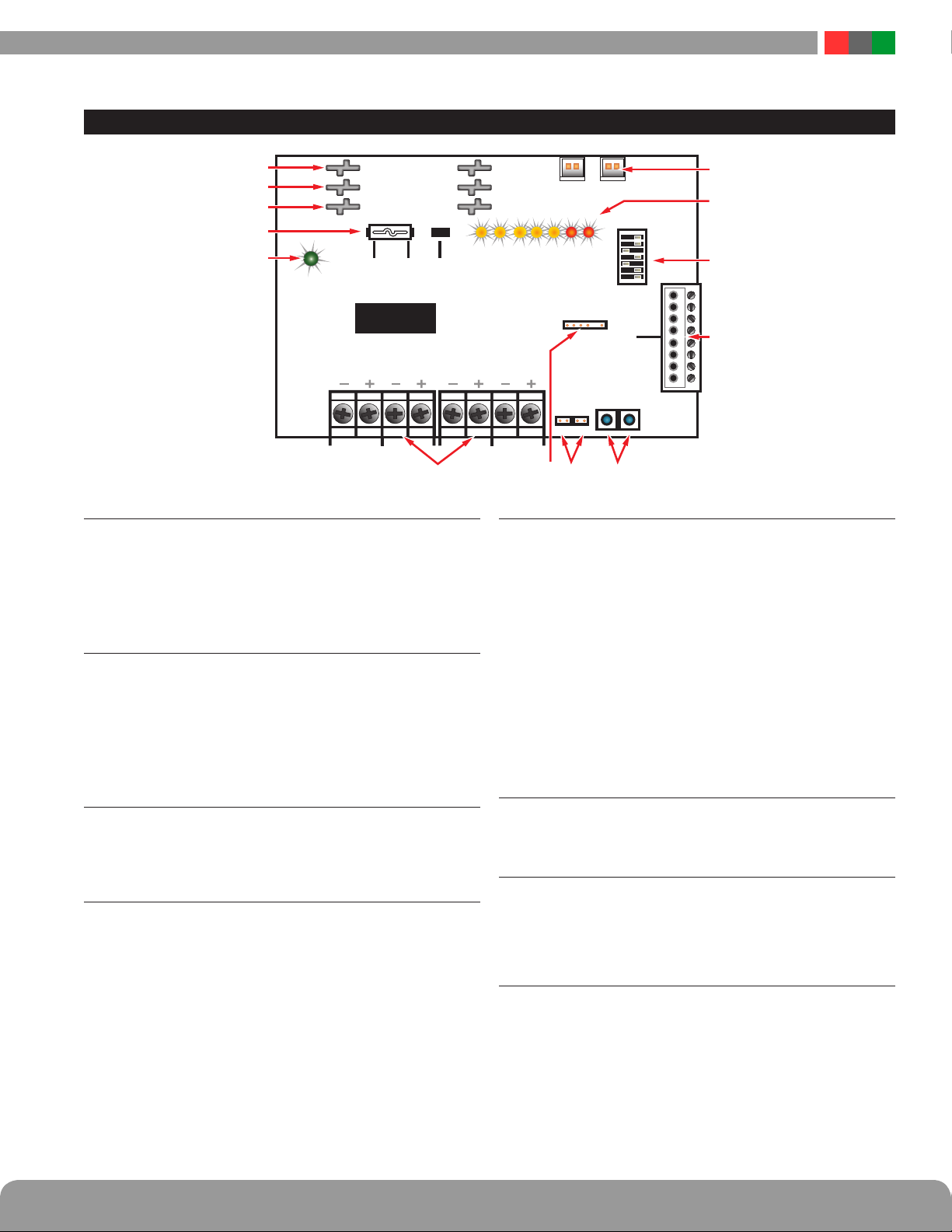
N24 – Accessory Overview
B1
B2
BR
B1 Connectors (J1 & J2)
1
These fastons are for connection to the B1 voltage buss in
the system. The voltage on the B1 buss comes from the DC1
faston of an FPO power supply. This voltage will supply the
outputs of the N24 board when the input fuse is set in the
“B1” position.
B2 Connectors (J5 & J6)
2
These fastons are for connection to the B2 voltage buss in
the system. The voltage on the B2 buss comes from the DC1
faston of an FPO power supply in a dual voltage system. This
voltage will supply the outputs of the N24 board when the
input fuse is set in the “B2” position. If the N24 is being used
in a single voltage system, these fastons can be left unused.
BR Connectors (J3 & J4)
3
The DC common buss in the system. All boards in the system
must have their BR fastons wired together for proper operation
(except for hybrid systems with both AC and DC output voltages).
Input Fuse (JP4, JP5, & JP6)
4
The input power source can be selected by placing the input fuse in the appropriate position. The B1 and B2 markings correspond with the B1 and B2 power inputs. See the
Specifications section of this manual for fuse type and ratings.
F1 F2
N24 Board
N24
Com FLT
B1
B2
BR
OUT3
OUT4
DataLink
FlexIO FlexIO
OUT1
OUT2
IN2
IN1
1
ON
2
3
4
5
6
7
A
IN1 IN2
B C D A B C D
OUT 1OUT 2OUT 3OUT 4
NAC Output Terminals (TB1 & TB2)
5
The NAC outputs of the N24 board. The outputs are configurable
as four class B outputs, two class A outputs, or one class A and
2 class B outputs. Output configuration is set by Dip Switches 3
and 4 in SW3 (See chart in item 10).
Any output configured as a Class B output requires a 4.7K ohm
resistor to be used as an EOL at the last device on the loop.
Outputs configured as Class A do not require an external EOL.
(See output example wiring diagrams for details on Page 4.)
These terminals are supervised and can accept synchronized
devices based on the settings of SW3.
These terminal strips are non-removable and accept wire
sizes from AWG12-AWG22.
DataLink Connection
6
For use with a LifeSafety Power NL1 board. See the NL1
manual for more information.
FAI Bridge Jumpers (JP1 & JP2)
7
These jumpers connect the FAI buss of the FPO power supply
system to the input(s) of the N24 to allow activation of the N24
by a dry contact connection on the FAI input of the FPO power
supply. In typical installations these jumpers are left OFF.
Test Buttons (SW1 & SW2)
8
These buttons allow testing of the N24 and its output
circuits without the need to alarm the entire FACP. Press SW1
to simulate activation of Input 1 and press SW2 to simulate
activation of Input 2.
 Loading...