

LifeSafety Power FlexPower C4, FlexPower C4P, FlexPower C8, FlexPower C8P Installation Manual
C4/C4P, C8/C8P Installation Manual
LifeSafety Power, Inc. | PH 888.577.2898 | TechSupport@LifeSafetyPower.com
P03-006 Rev A15
C4,C4P / C8, C8P Installation Manual
Table of Contents
Description .....................................1
Specifications ...................................1
Regulatory Information ............................1
Mounting the Power Control Modules ................1
Power Control Accessory Overview. ..................2
Connecting the Power Control Modules ...............4
Input and Output Wiring ...........................5
Common Jumper Settings .........................6
C4/C4P Application Example ........................7
C8/C8P Application Example ........................8
Description
The C4/C4P/C8/C8P power control modules add 4 or 8 zones
respectively, to an FPO power supply system. The C4/C4P/
C8/C8P accept either one or two voltage sources, either of
which are selectable for output on a zone-by-zone basis. Each
zone is fully controllable via a zone input which accepts a voltage, relay contact, or open collector input. Each zone output is
selectable for FAI operation, fail-safe or fail-secure, and voltage or relay contact output. The suffix "P" added to the model
number denotes Class 2 Power Limited outputs.
Regulatory Information
The equipment discussed within this manual has been tested
to the following standards:
• UL294, UL603, UL1076
• ULC S318, ULC S319
• CSA C22.2 #205
• CSFM Approved
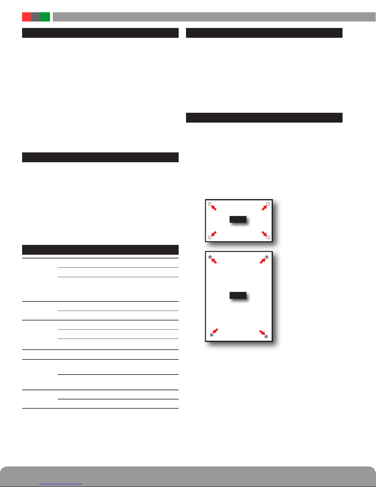
Mounting the C4/C4P/C8/C8P Power Control Modules
Mounting of the board to an enclosure is via the four
snap-in standoffs supplied.
1. Locate the appropriate mounting holes in the enclosure
and snap the standoffs into the holes.
2. Align the board mounting holes with the standoffs (be
sure the PC board is properly oriented) and snap the
board onto the standoffs.
C4
Specifications
Power Input
Zone Input
Zone Output
Fuse
Size
Weight
Voltage 12 or 24VDC nominal
Current 12A maximum
Standby Current 350mA (C4)
Voltage Input 12 or 24VDC
Max Current 10mA
Voltage Same as input
C4/C8 Current
C4P/C8P Current
3A ATM automotive style (C4/C8 only)
C4/C4P
C8/C8P
C4/C4P 0.20lb (0.10kg)
C8/C8P 0.35lb (0.16kg)
700mA (C8)
All lock control relays active
3.0A resistive
2.5A resistive (Class 2 Power Ltd)
4.00" x 2.50" x 1.0"
(102mm x 64mm x 25 mm)
6.00" x 4.00" x 1.0"
(152mm x 64mm x 25 mm)
C8
Class 2 power limited wiring must be seperated from non-power limited
wiring by a minimum of 1/4 inch and must use seperate knockouts.
• The installation and all wiring methods shall be in accordance with ANSI/
NFPA70 and all local codes.
For ULC compliance, installation and all wiring methods shall be in accordance with the Canadian Electrical Code, C22.1, Part I, Section 32 .
All input wiring to the module shall be located within the same room (3 m).
2 3
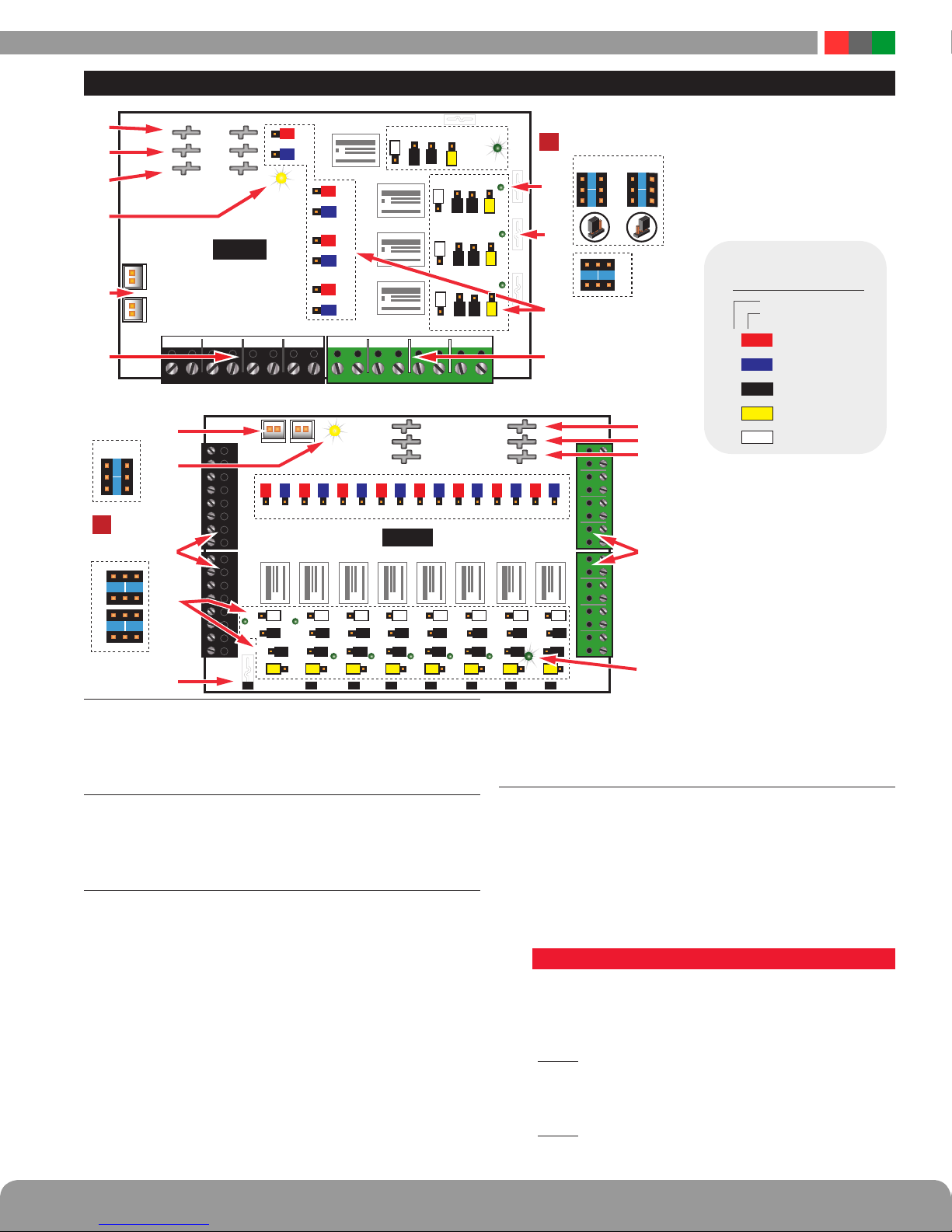
Power Control Accessory Overview
R
B1
B2
1A
2
1
BL
1B
BR
FAULTFAULT
C4/C4P
FlexIOFlexIO
INPUT FIELD WIRING 1–4 OUTPUT FIELD WIRING 1–4
2A
2
1
2B
BL
3A
R
2
1
3B
BL
4A
R
2
1
4B
BL
O1A+
A B
1
2
Note Jumper
Position
I
Orientation
F
1 2
E
C
1 2
INPUT FIELD WIRING
D
FlexIO Connectors
1
These connectors pass the FAI and Fault signals to and
from the C4/C4P/C8/C8P board and pass the FlexIO buss on
to other accessory boards in the system.
Fault LED (FLT) – Yellow
2
This LED lights when the C4/C4P/C8/C8P detects a ruptured
output fuse. This fault condition also transmits to the FPO
power supply.
Zone Inputs (IN1 – IN4/IN8)
3
These are the zone input terminal strips. These terminal strips
are removable and accept wire sizes from AWG14 – AWG22.
The terminals are labeled on the PC board near the terminal
strip. See the Input Wiring section of this manual for more
information.
• When using a relay contact input, the contact is connected
across the A and B terminals. When configured for a relay
contact input, it is normal to measure a voltage across these
two terminals. This voltage is current limited and will not
damage the activation contact.
• When using a voltage input, the voltage is connected to
the B terminal. The activation voltage must be common
grounded with the system voltage. The activation voltage
must be between 12 and 24VDC nominal.
FlexIOFlexIO
1
R
8A 8B
8F 7F 6F 5F 3F 2F 1F
8E 7E 6E 5E 4E 3E 2E 1E
F8
1
BL R BL R BL R BL R BL R BL R BL R BL
2
2
7A 7B
6A 6B
RL8 RL7 RL6 RL5 RL4 RL3 RL2 RL1
W W W W W W W W
21 21 21 21 21 2121
k Bk
B
7C8C 6C 5C 4C 3C 2C 1C
Bk Bk Bk Bk Bk Bk Bk Bk
21 21 21
7D8D 6D 5D 4D 3D 2D 1D
Y Y Y Y Y Y Y Y
F7 F6 F5 F4 F3 F2 F1
1F 1E
1
W
B
k
2
O2A+
O1B-
O2B-
O3A+ O3B- O4A+ O4B-IN1A IN1B IN2A IN3A IN3B IN4A IN4BIN2B
FAULTFAULT
1
1
2
2
5A 5B
4A 4B
C8/C8P
W
Bk Bk Bk Bk Bk Bk
21 21 21 21 21
1
Bk
2
2F 2E
W
3F 3E 3D3C
W
4F 4E 4D4C
W
B1
B2
BR
1
2
1D1C
Y
1
1
Bk
2
1
B
2
1
2
3A 3B
Important: Note Jumper
I
Position Orientation
F E
2D2C
1
B
k
Y
2
1
1
k
Bk
Y
2
1
1
B
B
k
k
Y
2
B1
B2
BR
1
1
2
2A 2B
1
2
2
1A 1B
1
2
2 1
C D
1
2
A
B
WIRING 5-8
OUTPUT FIELD
JUMPER
PROGRAMMING
Reference
Jumper Color
RED
A FAI
BLUE
B
C&E
D
F
INVERT input
BLACK
WET/DRY output
YELLOW
V SELECT
WHITE
INVERT output
I
Note: The relay contact output
has a suppression diode across
it, and cannot be used to switch
AC voltage.
To switch DC voltage with these
contacts, Terminal “B” should
WIRING 1–4
OUTPUT FIELD
be positive, “A” negative.”
• When using an open collector (transistor) input, place a jumper
across the A and B terminals and connect the open collector
to the B terminal. Note that the input source must be common
grounded with the C4/C4P or C8/C8P board’s power source.
Configuration Jumpers (xA–xF)
4
These jumpers program the zone’s input, output, and FAI
operation. Jumpers are color coded for ease of programming and jumper numbers correspond with the zone
number (e.g. 1A is jumper A for Zone 1).
OBSERVE JUMPER ORIENTATION CAREFULLY - See the
Common Jumper Settings Chart for more information.
Jumpers and their possible settings are as follows:
• Jumper A - RED (Zone FAI Enable)
This jumper enables or disables FAI for the selected zone.
The FAI control input is on the FPO power supply board.
See Appendix A of the FPO manual for more information
on the FAI Input.
Pos. 1 (FAI Enabled) When this jumper is placed in posi-
tion 1, the zone's output will invert when the input
is active. This is typically used to drop power to
maglocks on a fire alarm condition.
Pos. 2 (FAI Disabled) When this jumper is in position 2,
FAI will have no effect on the zone's output.
C4,C4P / C8, C8P Installation Manual
Jumper B - BLUE (Input Invert)
This jumper is used to select a fail-safe or fail-secure input.
Adjust this jumper so that the zone's output LED is FLASHING when the door is unlocked.
Pos. 1 (Fail Safe) Use this position for a NC contact input
(contact OPENS to unlock door) or for a voltage
input where the voltage is REMOVED to unlock
the door.
Pos. 2 (Fail Secure) Use this position for a NO contact input
(contact CLOSES to unlock door) or for a voltage input where the voltage is APPLIED to unlock the door.
Jumpers C & E - BLACK (Wet or Dry Output Selection)
These jumpers select whether the output is a relay contact output or a voltage output. BOTH jumpers must be
set to the same position for proper operation.
I The outputs of the C4 and C8 have built-in reverse protection di-
odes across each output. If a delay is present on lock release, or when
using as a dry relay contact output, the diode can be removed from the
circuit. See page 6 for more information.
Pos. 1 (Relay Contact Output) By placing both jumpers
in Position 1, the zone's output is set as a relay
contact output.
Pos. 2 (Voltage Output) By placing both jumpers in posi-
tion 2, the zone's output is set to output the voltage of the buss selected by Jumper D (See below).
Jumper D - YELLOW (Voltage Buss Selection)
The C4 and C8 can each accept up to two power supply
inputs connected to B1 and B2. This jumper selects which
of the two power supply inputs are used for the zone's
output. If only a single power supply is being used, set
this jumper for Position 1. (Note: if the zone's output is
set as a relay contact output, this jumper has no effect.)
Pos. 1 (B1 Buss) This position selects the power supply
connected to the B1 input of the C4 or C8 board.
Pos. 2 (B2 Buss) This position selects the power supply
connected to the B2 input of the C4 or C8 board.
Jumper F - WHITE (Output Invert)
This jumper is used to select a fail-safe or fail-secure
output. Adjust this jumper so that the door is UNLOCKED
when the zone output LED is flashing (Zone Active).
Pos. 1 (NO / Voltage when input is activated) When in Po-
sition 1, the output terminals will connect through
the NC contact if set for a relay contact output or
will output a voltage when the input is activated.
Pos. 2 (NC / Voltage when input is deactivated) When in
Position 2, the output terminals will connect through
the NO contact if set for a relay contact output or will
not output a voltage when the input is activated. This
position is typically used for Mag Locks.
Output Fuses (F1 – F8) – Optional
5
When using the fused version of the C4/C8, these are the
fuses for each zone output. Fuse numbers correspond with
the zone number (e.g. F1 is the fuse for OUT1). When using
the PTC version of the C4/C8, the fuse will be replaced with
a soldered-in PTC. Fuses or PTCs are not in the circuit when
the zone is configured as a relay contact output.
Output LEDs (01 – 08) – Green
6
These LEDs indicate the status of the output. LED numbers
correspond with the zone number (e.g. O1 is for Output 1).
• On SteadyDoor Locked (Fuse or PTC Intact)
• FlashingDoor Unlocked (Either due to Zone Input or FAI)
• OffFuse or PTC open
These LEDs are bi-color and indicate the output voltage for
each output as follows:
• Green – 12V Output
• Blue – 24V Output
I
NOTE LED colors are range based. Voltage Less than 13V
will show Green. Voltage above 20V will show Blue. Voltage
between 13 and 20 may show either voltage or a combination
Green & Blue. Always verify voltage with a voltmeter.
I Note that if an Output LED is operating opposite from
expected (flashing in normal state, steady when the input is activated), but the output terminals are behaving
as expected, then jumpers B and F should be placed
into the opposite position.
Zone Outputs (01 – 04/08)
7
These are the output terminal strips. These terminals are
removable and accept wire sizes from AWG14 – AWG22.
The terminals are labeled on the PC board near the terminal
strip. See the Output Wiring section for more information.
• Relay Contact Outputs are across the A and B terminals. The
selection for NO or NC is made by jumper F
• Voltage (Wet) Outputs are across the A and B terminals.
– Positive is terminal B
– DC Common is terminal A
IThe C4 and C8 have reverse protection diodes across
each output. If a delay is present on lock release, or when
using as a dry relay contact output, the diode can be re-
moved from the circuit. See page 6 for more information.
BR Connectors (J4 & J5)
8
The DC Common buss in the system. All DC boards in
the system must have their BR fastons wired together for
proper operation.
B2 Connectors (J6 & J7)
9
These are for connection to the B2 buss in the system. The
voltage on the B2 buss comes from an FPO power supply or a
B100 secondary supply in dual voltage systems. This voltage
will be directed to any outputs whose yellow jumper (Jumper
D) is set in the B2 position. If the C4/C8 is being used in a
single voltage system, these fastons can be left unused.
B1 Connectors (J2 & J3)
bk
These are for connection to the B1 buss in the system. The
voltage on the B1 buss comes from an FPO power supply.
This voltage will be directed to any outputs whose yellow
jumper (Jumper D) is set in the B1 position.
4 5
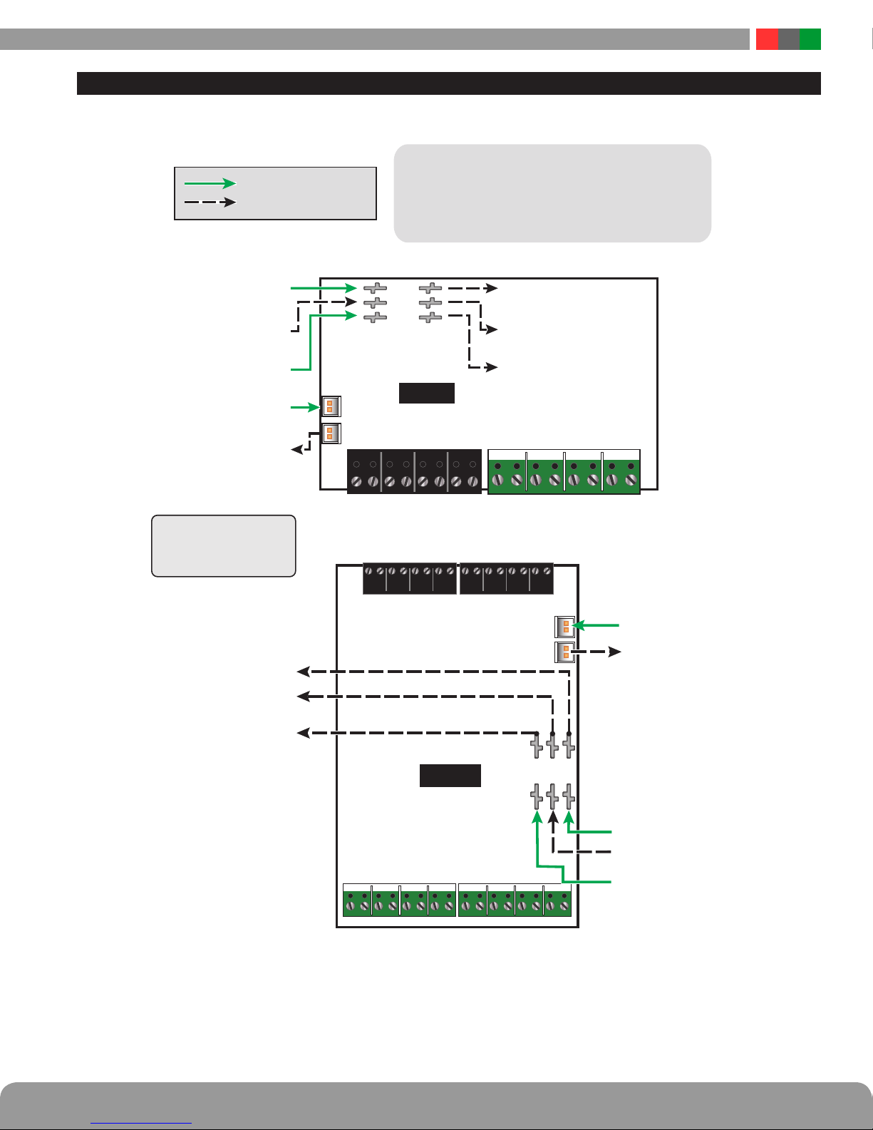
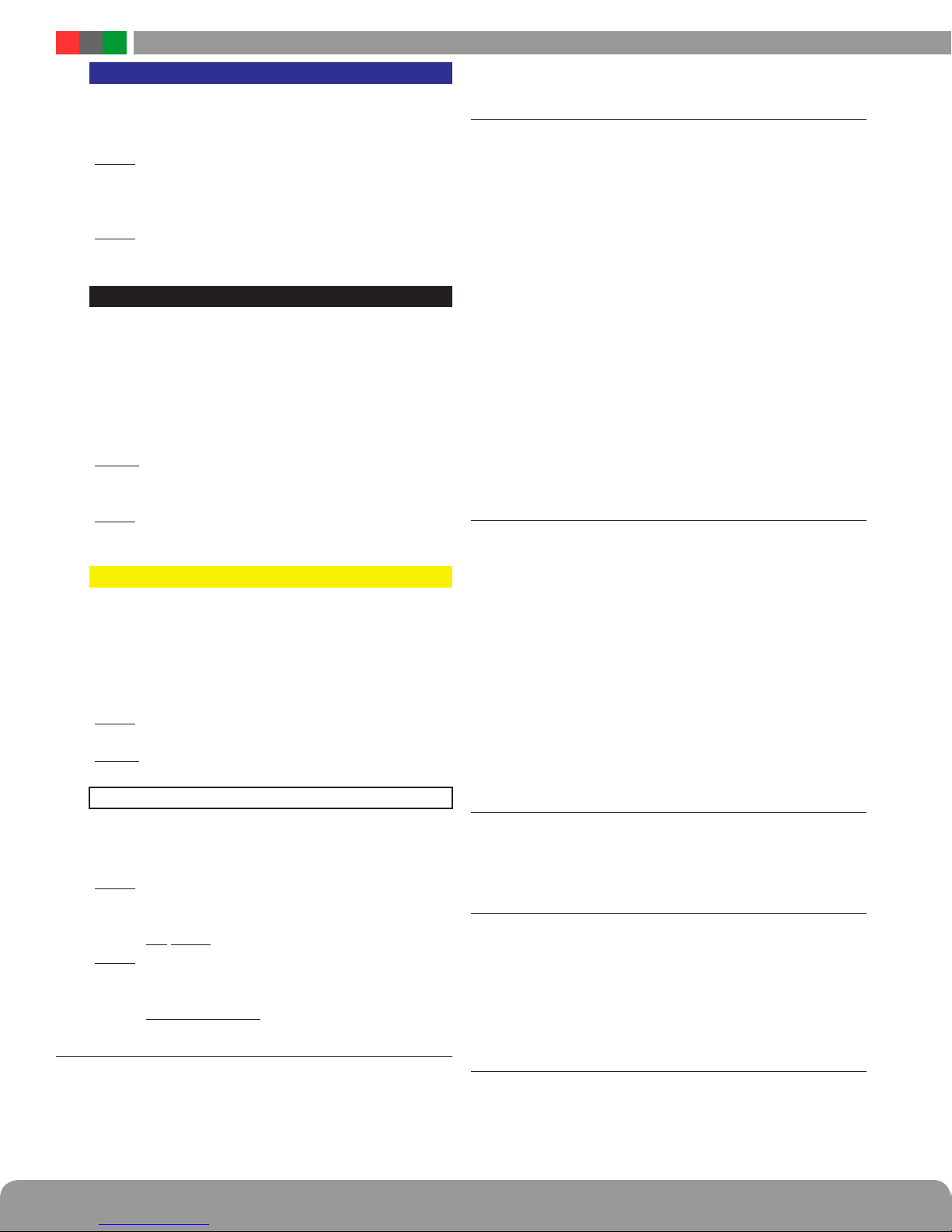
Connecting the Power Control Module
Remove all AC and battery power from the FPO system before adding or replacing a power control board.
h
Each of the B1, B2, BR, and FlexIO busses has two connectors.
Required Connections
Optional Connections
Input from Main
DC voltage source
Input from Second
DC source (optional)
These connectors may be used interchangeably.
For example: FlexIO from the power supply may be connected
to either of the C4/C8's FlexIO connectors, the Main DC voltage
source may connect to either B1 terminal, etc.
B1
B2
BR
Main DC voltage continues
to other accessories
Second DC Source continues
to other accessories
BR in from System
FlexIO in from System
FlexIO continues to
other accessories
Note:
B1 terminals are interconnected
B2 terminals are interconnected
BR terminals are interconnected
Main DC voltage continues
to other accessories
Second DC Source continues
other accessories
BR continues to
other accessories
BR continues to
C4/C4P
other accessories
FLEXIOFLEXIO
INPUT FIELD WIRING 1–4 OUTPUT FIELD WIRING 1–4
O1A
O1B
O2A
O2B
O3A O3B O4A O4B
– +– +– +– +
NOTE - Output polarity has changed -
Verify polarity via markings on the PCB
INPUT FIELD WIRING 1–8
FLEXIOFLEXIO
C8/C8P
B1B2BR
FlexIO in from System
FlexIO continues to
other accessories
NOTE - Output polarity has changed -
Verify polarity via markings on the PCB
OUTPUT FIELD WIRING 1–8
O1A
O2A
O1B
O2B
O3A O3B O4A O4B
– +– +– +– +
O5A
O5B
O6A
O6B
O7A O8B
– +– +
Input from Main
DC voltage source
Input from Second
DC source (optional)
O8A
O7B
– + – +
BR in from System
 Loading...