

LifeSafety Power B100, FLEXPOWER B100 Installation Manual
B100 Installation Manual
Description
The B100 provides an additional voltage in a FlexPower system. This voltage can either be accessed directly via the B100's
terminals or through other FlexPower Accessory Boards. The
B100’s input is typically supplied by the B1 buss in the system,
allowing the FPO’s battery set to back up the B100’s output
voltage without the need for a second battery set. Output settings for the B100 include a fixed 12V setting and an adjustable
setting of 5 to 18V. Multiple B100s can be added to a system
for virtually unlimited voltage combinations.
Specifications
Input Voltage 8-25V (Must be at least 3V above
output voltage setting)
Current 3.5A maximum
Standby Current 35mA
Output Voltage 5-18V
Current 4A maximum
(Class 2 Power Limited)
Fuse 7.5A ATM automotive style
Size
Weight 0.20lb (0.09kg)
4.00" x 2.50" x 1.75"
(102mm x 64mm x 45 mm)
Regulatory Information
The equipment discussed within this manual has been tested
to the following standards:
• UL294, UL603, UL864, UL1076, UL1481, UL2044, UL2572
• ULC S318, ULC S319, ULC S527
• CSA C22.2 #107.1
• CSFM Approved
1.3
• z
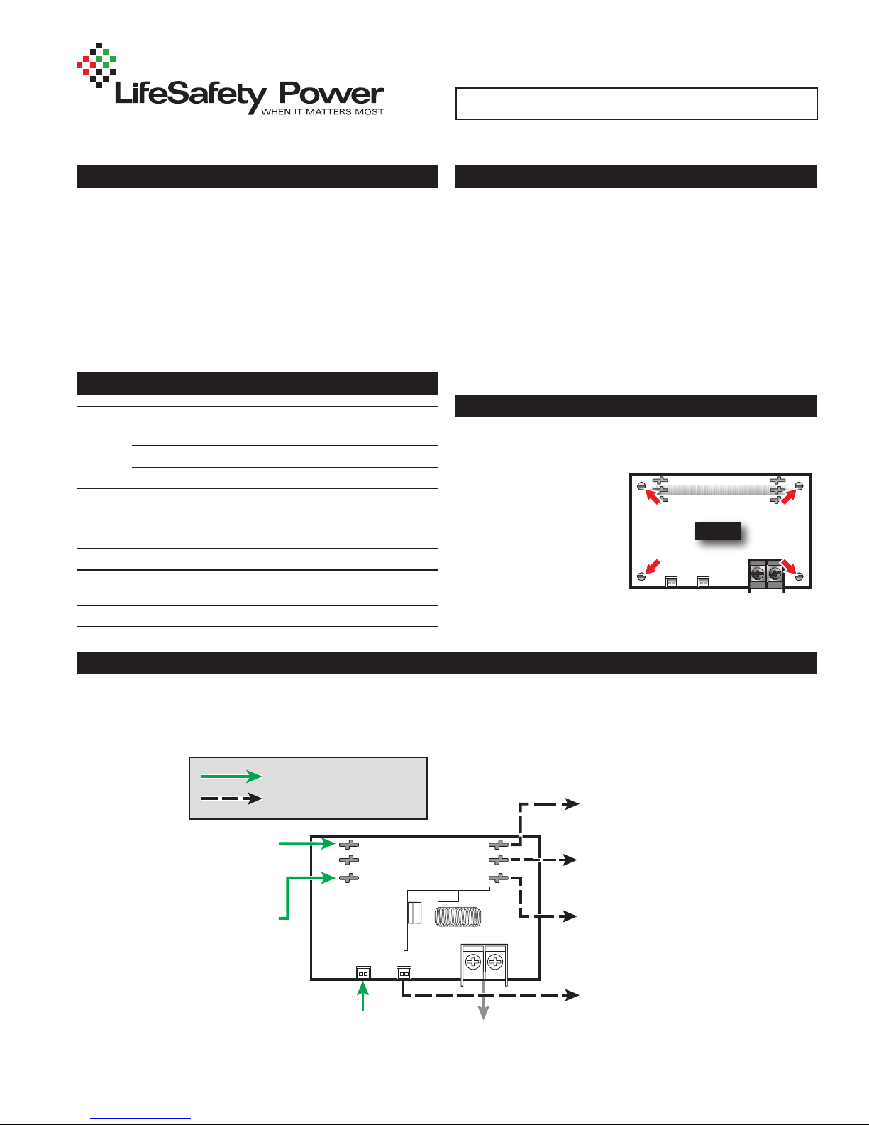
Mounting the B100 Secondary Power Supply
Mounting of the B100 Board to an enclosure is via the four
snap-in standoffs supplied.
1. Locate the appropriate
mounting holes in the
enclosure and snap
the standoffs into the
holes.
2. Align the board mounting holes with the
standoffs (be sure the PC board is properly oriented)
and snap the board onto the standoffs.
B100
Connecting the B100 Secondary Power Supply
Remove all AC and battery power from the FPO system before adding or replacing a B100 board.
h
Observe polarity of the DCIN and BR Connections or damage to the system could occur.
h
Required Connections
Optional Connections
DC Input from System
(Typically the DC1 output
of an FPO power supply)
BR in from System
I The DC In, DC Out, and BR terminals run
through the board for daisy chaining and each
terminal set is interchangeable from a functional
standpoint.
Either DC IN may be used, either DC Out may be
used or either BR may be used interchangeably.
DC IN
DC OUT
BR
FlexIO
in from System
DC IN
DC OUT
BR
– OUT +
DC OUT terminals to
device to be powered
Input voltage continues to other
accessories (typically to B1 Buss – ensure
no other voltage sources on this buss)
B100’s output to other accessories
(typically to B2 Buss – ensure no other
voltage sources on this buss)
BR continues to other accessories
FlexIO continues to other accessories
P03-005 Rev A09
B100 INSTALL MANUAL 2
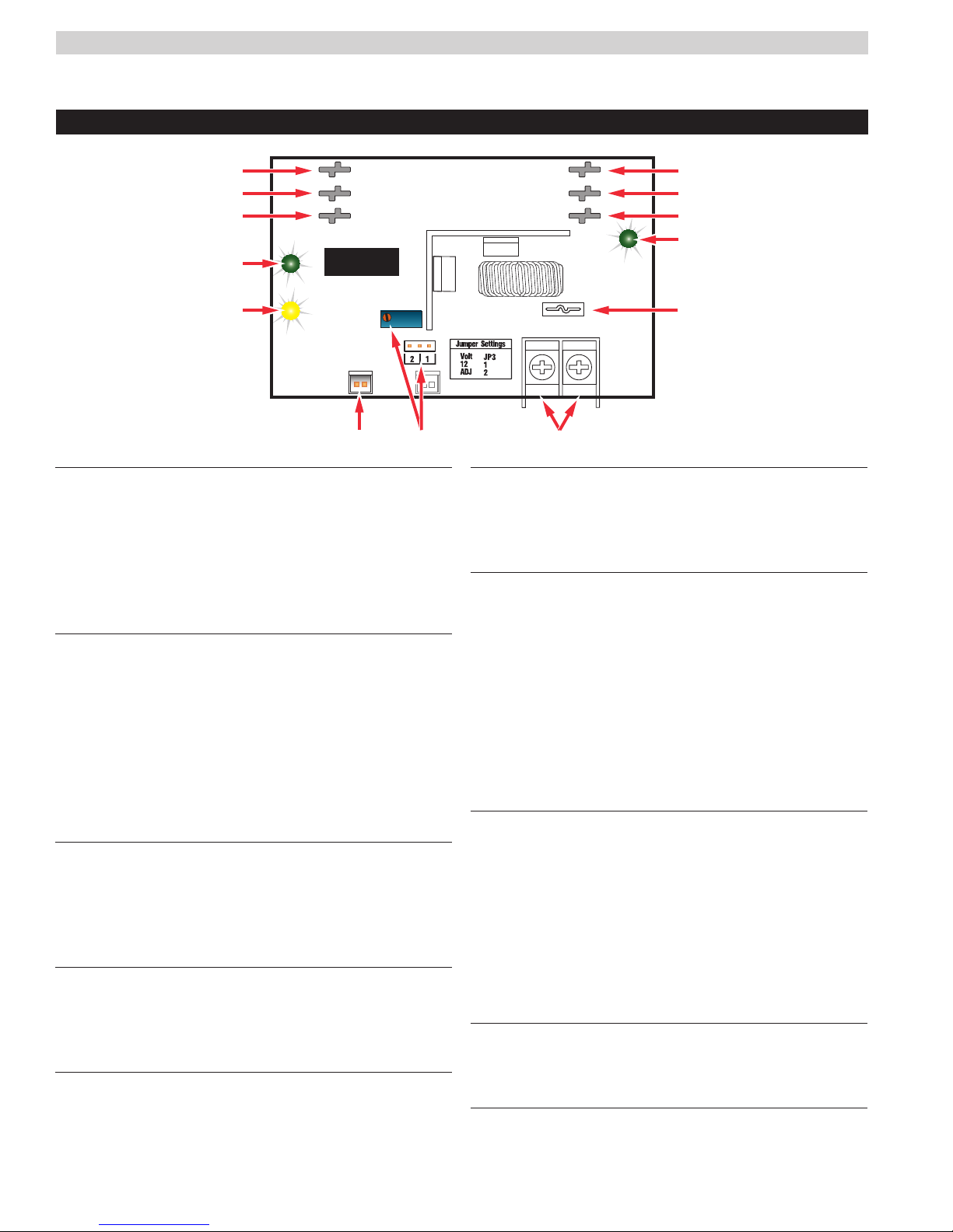
B100 – Secondary Power Supply
DC In
DC IN
DC OUT
BR
B100
Fault
DC IN Connectors (J1 & J4)
1
These fastons are the input to the B100. Either faston
may be used as the input. Two connections are provided
to allow this voltage to pass through to other accessory
boards in the system. This input voltage must always be at
least 3 volts above the output voltage setting for the B100
to maintain its output.
DC OUT Connectors (J2 & J5)
2
These fastons are the output of the B100 for connection
to other accessories in the system. This output may
be considered as an equivalent to the DC1 faston of an
FPO power supply.
Either or both DC OUT fastons may be used in the system.
I Ensure there are no other voltage sources connected
to the buss before powering the system or damage
WILL occur.
BR Connectors (J3 & J6)
3
The DC Common buss in the system. All boards in the
system must have their BR fastons wired together for
proper operation (except for between the DC and AC
sections of an FPX hybrid system).
DC IN LED (D1) – Green
4
This LED indicates the availability of voltage on the DC
IN Buss. When voltage is available on the buss, the LED
is lit.
FAULT LED (D7) – Yellow
5
This LED lights when the B100 detects a fault condition. This
fault condition also transmits to the FPO power supply
Fault conditions detected include ruptured output fuse, no
output, output overload, or output voltage out of regulation.
DC IN
DC OUT
BR
DC Out
– OUT +
FlexIO Connectors (JP1 & JP2)
6
These connectors allow the fault status of the B100 to be
transmitted to the FPO power supply and pass the FlexIO
buss on to other accessory boards in the system.
Output Voltage Selection (JP3 & VR1)
7
This jumper selects the output voltage for the B100 and
the potentiometer sets the output voltage when in the
adjustable range. In adjustable range, voltage may be
set from 5 to 18VDC.
Possible jumper settings are as follows:
• 12V Out JP3 Position 1
• Adjustable OutputJP3 Position 2
I The VR1 potentiometer will have no effect unless
the jumper is set for the adjustable range.
DC Output
8
This is the output terminal strip. This terminal strip is
non-removable and accepts wire sizes from AWG12 –
AWG22. The terminals are labeled on the PC board by
the terminal strip.
I
CAUTION When powering magnetic loads such as
maglocks, door strikes, solenoids, etc, each of these
loads must have a reverse protection diode either built-in
or external to the device.
Output Fuse (F1)
9
This fuse protects the DC Output terminals. It does not
protect the DC OUT faston.
DC OUT LED (D4) – Green
.
bk
This LED indicates the availability of voltage on the DC
OUT Buss. When voltage is available on the buss, the
LED is lit.

B100 INSTALL MANUAL 3
B100 Current Loading
Power drawn from the B100 subtracts from the power available from the FPO supplying the B100. The most accurate
way to determine the draw from the FPO is to calculate the actual power draw and factor in the efficiency of the B100.
PI = PO*1.15
Where:
PI = Input power of the B100
PO = Output power draw on the B100
B100 Current Load Examples
Example: 1
An FPO250 set for 24V is powering a B100. The B100 is set for
an output of 12V and has a 3A total load connected.
PO = 12V*3A = 36W
PI = 36W * 1.15 = 41.4W
In this example, the B100 will draw 41.4W from the FPO250
This leaves 208.6W available from the FPO250
Example: 2
What size FPO do I need to create a dual voltage power supply
providing 12V@4A and 24V@6A?
12V x 4A x 1.15 = 55.2 Watts
24V x 6A = 144 Watts
144W + 55.2W = 199.2W
The next greater FPO to 199.2 is 250
Use an FPO250 power supply with the B100 converter
Example: 3
What size FPO do I need to create a dual voltage power supply
providing 12V@1A and 24V@3A?
12V x 1A x 1.15 = 13.8 Watts
24V x 3A = 72 Watts
13.8W + 72W = 85.8W
The next greater FPO to 84 is 150
Use an FPO150 power supply with the B100 converter
 Loading...