

LifeSafety Power FlexPower Installation Manual

FlexPower
DC Power System Installation Manual
LifeSafety Power, Inc. | PH 888.577.2898 | TechSupport@LifeSafetyPower.com
P03-40 Rev A15
FlexPower DC Power System Installation Manual
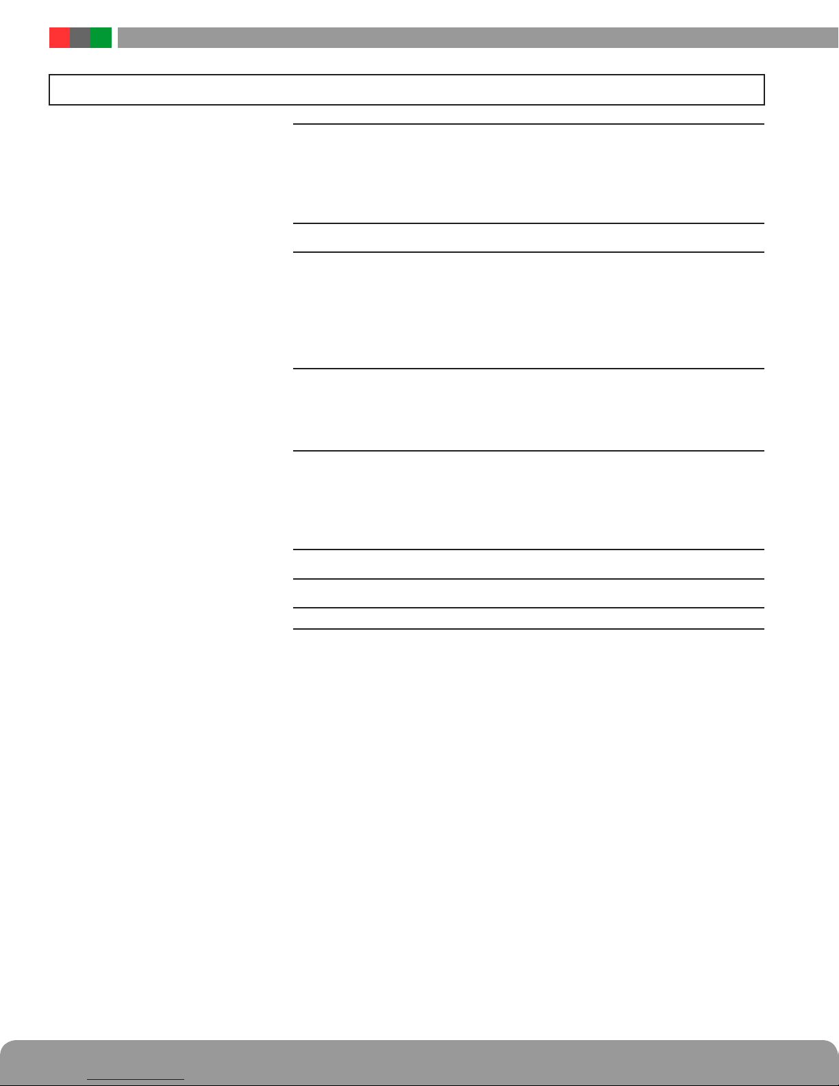
Table of Contents
Notes and Warnings ......................................iii
Symbol Definitions ............................................................ iii
Warnings.................................................................... iii
Regulatory Information ......................................................... iii
Conventions Used Within this Manual.............................................. iii
Power Supply Quick Start ..................................iv
Section 1 – Installation and Operation .........................1
1.1 Mounting .................................................................1
1.2 Jumper / LED / Connector Descriptions ..........................................3
1.3 FAI Input Usage ............................................................6
1.4 Typical Installation & Wire Routing .............................................7
1.5 Power-Up and Basic System Verification Checklist .................................8
Section 2 – Troubleshooting and Maintenance ....................9
2.1 Troubleshooting Table .......................................................9
2.1 Troubleshooting Table (continued) .............................................10
2.2 Maintenance Instructions ....................................................10
Section 3 – Specifications ................................. 11
3.1 Electrical Specifications .....................................................11
3.2 Temperature Specifications ..................................................13
3.3 Mechanical Specifications ...................................................13
3.4 Replacement Parts .........................................................14
Appendix 1 – Tamper Switch Wiring .......................... 15
Appendix 2 – User Certificate............................... 16
Appendix 3 – UL Compliance Verification Sheet .................. 17
ii iii

Notes and Warnings
Symbol Definitions
The following symbols are used throughout this manual:
This symbol is intended to alert the installer of shock
h
hazards within the enclosure. Service should only be
performed by qualified service personnel
This symbol is intended to alert the installer of important
i
information intended to help the installer avoid personal
injury or property damage
Warnings
Installation and service should be performed only by
h
qualified service personnel and should conform to all
local codes
To reduce the risk of electric shock or fire, do not
h
expose this equipment to rain or moisture
This equipment shall be installed in a manner which
i
prevents unintentional operation by employees,
cleaning personnel, or others working in the premises, by falling objects, customers, building vibration,
or similar causes
This equipment is not intended for use within the pa-
i
tient care areas of a Health Care Facility
Replace fuses only with the same type and rating as
h
indicated in the specifications section of this manual.
Regulatory Information
The equipment discussed within this manual has been tested to the following standards:
• UL294, UL603, UL1076
• ULC S318, ULC S319
• CSA C22.2 #107.1, CSA C22.2 #205
FCC Information
Note: This equipment has been tested and found to comply
with the limits for a Class A digital device, pursuant to Part
15 of the FCC Rules. These limits are designed to provide
reasonable protection against harmful interference when
the equipment is operated in a commercial environment.
This equipment generates, uses, and can radiate radio frequency energy and, if not installed and used in accordance
with the instruction manual, may cause harmful interference to radio communications. Operation of this equipment
in a residential area is likely to cause harmful interference in
which case the user will be required to correct the interference at his own expense.
Conventions Used Within this Manual
Positional information (e.g. top, bottom, up, down, left,
right, etc.) is referenced with the board or enclosure in the
orientation shown in the illustrations in this manual.
To prevent impaired operation, ensure that all wiring
i
is routed and secured to prevent accidental open or
short circuit conditions
The system and any batteries (if used) should be
i
tested at least once per year to ensure proper operation
Batteries (if used) should be maintained at an am-
i
bient temperature of between 32 and 120 degrees
Fahrenheit (0-49 Celsius) or premature loss of battery power could occur
FlexPower DC Power System Installation Manual
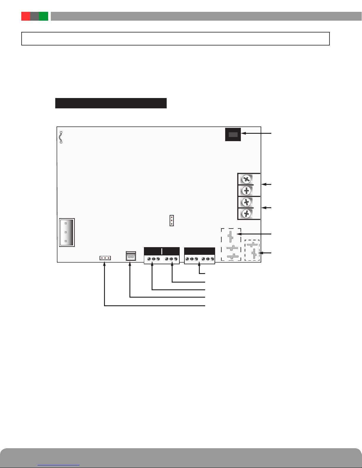
Power Supply Quick Start
This section gives a quick visual guide of installation connections and settings for installers already familiar with the FlexPower line of power supplies. For full information, please read this entire manual before installing.
QUICK INSTAL - SECTION FINDER
Cut for
230VAC input
section 1.2 #1section 1.2 #1
AC Input
section 1.2 #3section 1.2 #3
Models ending in "/E"
are factory preset for 230VAC
with JP1 jumper already cut
E GRND
Flex
Battery
Battery
Presence Jumper
Presence Jumper
section 1.2, #9
SYS AC
+ –+ –+ –+ –
FAI
FAI Input - section 1.2 #10 & section 1.3
Fault Contacts/AC - section 1.2 #8
Fault Contacts/System - section 1.2 #8
Flex IO Connector - section 1.2 #6
Earth Ground Jumper - section 1.2 #5
12/24 V Selection
section 1.2 #20
Main Output
section 1.2 #17
FAI Controlled Output
section 1.2 #16
FlexConnect
Accessory Power
section 1.2 #11
Battery Connection
section 1.2 #13
Figure 2
iv 1
Installation and Operation
Section 1 – Installation and Operation
The following pages cover the installation, setup, and basic operation of the FPO series power supplies.
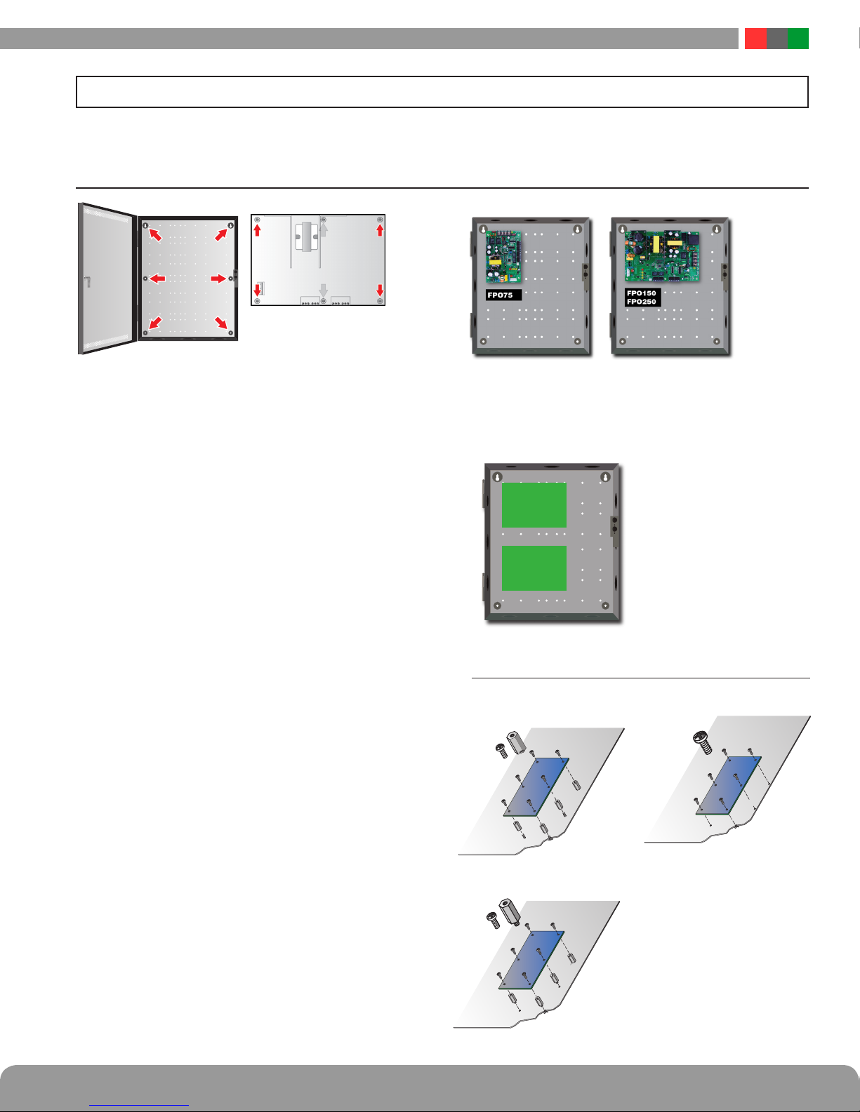
1.1 Mounting
Figure 1 Figure 2 Figure 3
Mounting an Enclosure
Use the following procedure when mounting a wall-mount enclosure
(figure 1).
1. (Optional) Remove the enclosure’s cover.
2. Locate the top keyhole mounting holes in the back of the enclosure.
3. Mark and pre-drill the locations for the keyholes in the mounting surface.
4. Partially install two fasteners appropriate for the surface on
which the enclosure is being installed. Leave the heads of the
fasteners approximately ¼" out from the surface. Minimum
fastener size should be #10 or larger.
5. Hang the enclosure on the two fasteners and mark the locations of the remaining mounting holes.
6. Remove the enclosure and pre-drill the locations for the remaining mounting holes.
7. Re-hang the enclosure on the top mounting fasteners, start
the remaining fasteners and tighten all fasteners.
8. Reinstall the enclosure’s cover, if removed in step 1.
i It is the installer’s responsibility to determine the ap-
propriate fastening system for use with the surface the
enclosure is being mounted to.
i For UL1076 applications, after installation is complete, the
installer must install the two supplied 1" long screws to the
edge of the enclosure's cover for additional security.
Mounting a Sub Assembly to an Enclosure
Third Party sub assemblies will be mounted in one of three methods
based on the supplied mounting hardware (figure 5).
FPO/FPV
larger
FPO/FPV
smaller
Figure 4
Screw
Female to female Stando
Screw mounting
Mounting an FPO PS Board to an Enclosure
Use the following procedure when mounting an FPO power supply to a LifeSafety Power enclosure (figure 2).
1. Locate the appropriate mounting holes in the enclosure and
snap the four or six standoffs provided into the holes.
2. Align the board mounting holes (mounting hole locations are
indicated in the drawing above) with the standoffs and snap the
board onto the standoffs. Be sure the board is properly oriented
before snapping the board onto the standoffs (Figure 3).
3. When two FPO/FPV boards are installed, the larger shall be
located on top (figure 4).
Screw
Male to female Stando
Figure 5
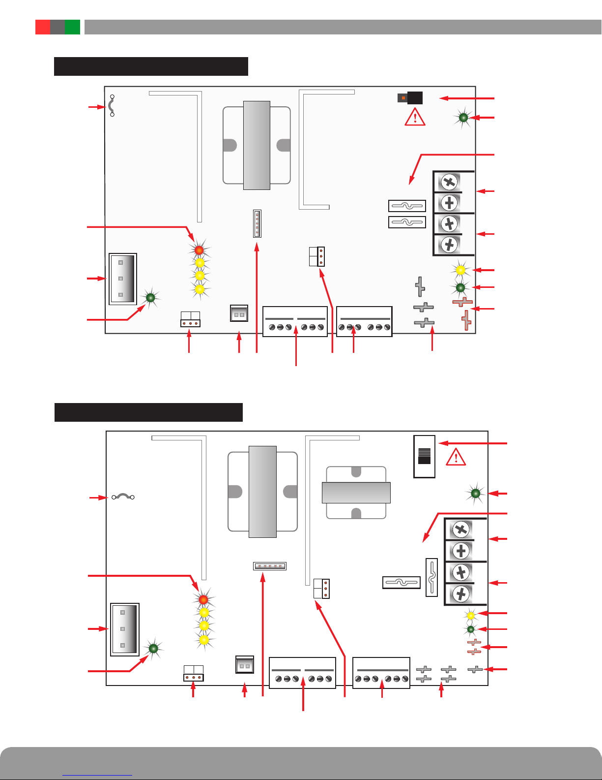
FPO75
FlexPower DC Power System Installation Manual
120/230VAC
Cut for 230VCut for 230V
AC Input
AC ON
Earth
GND DET
12V
24V
DC1
DataLinkDataLink
FAI
GND FLT
AC FLT
SYS FLT
1
2
Flex IO
2
Battery
Battery
Detect
Detect
1
AC FLTAC FLT
FAI INPUTFAI INPUTSYS FLTSYS FLT
For UL compliance, the AC fault contact
must be monitored by a Listed control panel
DC2 NODC2 NO
DC2 NCDC2 NC
DC1DC1
BRBR
DC2DC2
REV BAT
DC2
+
BB
–
BB
Observe battery polarity
Observe battery polarity
or damage may result
or damage may result
+ DC2 –+ DC2 – + DC1 –+ DC1 –
i
FPO150 / 250
120/230VAC
Cut for 230VCut for 230V
AC Input
AC ON
Earth
GND DET
12V
24V
DC1
DC2 NODC2 NO
DC2 NCDC2 NC
DC1DC1
V+V+
REV BAT
DC2
i
BRBR
+ DC2 –+ DC2 – + DC1 –+ DC1 –
–
BB
+
BB
DC2DC2
V-V-
DataLinkDataLink
2
Battery
Battery
Detect
Detect
FAI
GND FLT
AC FLT
SYS FLT
1
2
Flex IO
1
AC FLTAC FLT
Observe battery polarity
Observe battery polarity
or damage may result
or damage may result
FAI INPUTFAI INPUTSYS FLTSYS FLT
For UL compliance, the AC fault contact
must be monitored by a Listed control panel
2 3
 Loading...