

Life Link Response LLR-300 Installation Manual
Manufaturer’s Disclaimers and Limited Warranty
The Manufacturer’s Warranty period is one year from the time of purchase.
COMMUNICATION AND RESPONSE LIMITATIONS: Purchaser acknowledges that signals which are transmitted over
telephone lines, or other modes of communication pass through communication networks wholly beyond the control of
the Manufacturer and are not maintained by the Manufacturer, and, therefore, The Manufacturer shall not be responsible
for any equipment or communication failure which prevents transmission signals from reaching your contact list including
emergency 911 operators or damages arising therefrom. Purchaser acknowledges that the Manufacturer provides
no response to the System’s equipment. The equipment is designed to communicate with the a central station of your
choice and the Manufacturer is not and shall not be responsible for ambulance, police or other emergency response time or
that any response will be provided by the central monitoring station.
TESTING AND SERVICE OF THIS EQUIPMENT: The equipment, once installed, are in the exclusive possession and control
of the Purchaser, and it is Purchaser’s sole responsibility to test the operation of equipment and request warranty service if
the equipment is under warranty.
PURCHASER’S EXCLUSIVE REMEDY: Purchaser’s exclusive remedy for the Manufacturer’s default hereunder is to require
the Manufacturer to repair or replace, at the Manufacturer’s option, any equipment or part of the personal emergency alert
system which is non-operational during the Manufacturer’s warranty period.
LIMITATION OF LIABILITY: This equipment is not designed or guaranteed to prevent any loss or injury. This Limited
Warranty and Disclaimer of Liability constitutes the terms of sale and use of the equipment, and if there should arise any
liability on the part of the Manufacturer as a result of any cause whatsoever, regardless of whether or not such loss, damage,
or personal injury was caused by or contributed to by the Manufacturer’s negligence to any degree or failure to perform
any obligation or strict products liability, such liability will be limited to an amount paid by the Purchaser to the Manufacturer
for the product, or to the sum of $350.00, whichever is greater.
For warranty information, see your dealer for details.
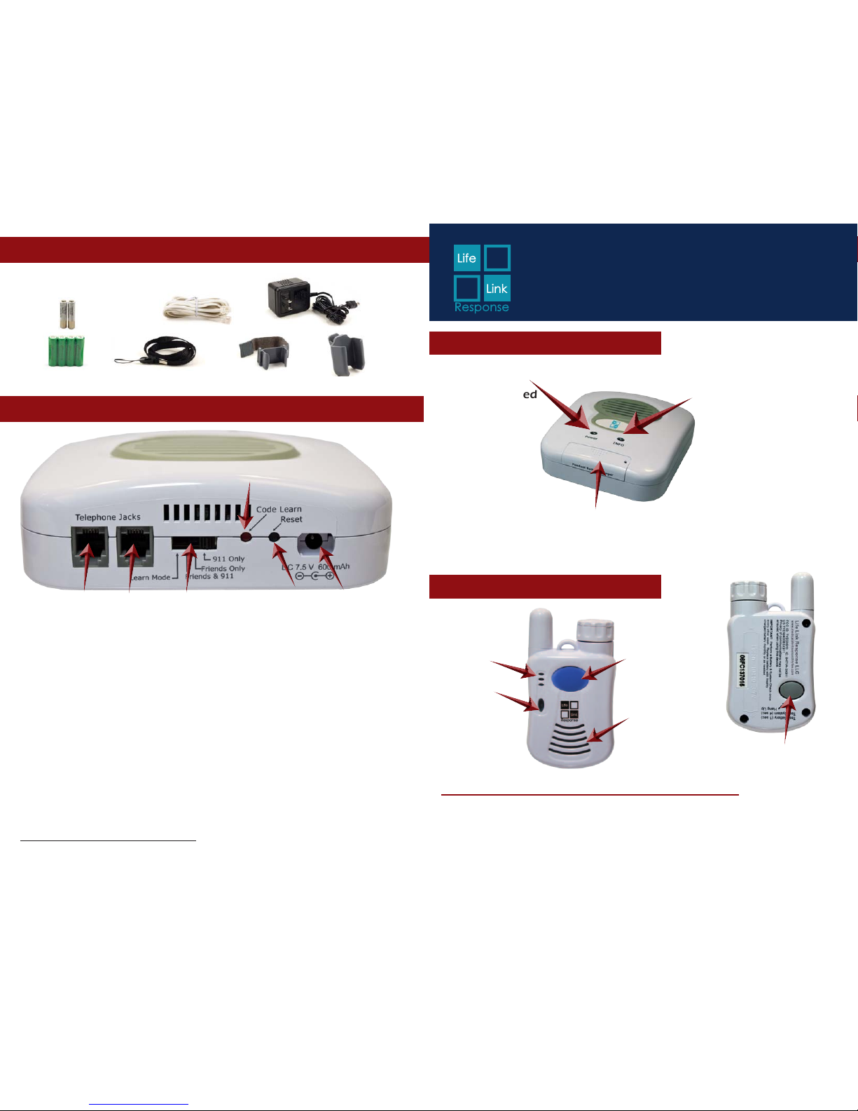
Telephone Jacks
Line IN
To House
Phone
Programming Switch
Reset
(Black)
Power DC 7.5
600 mAH
Code Learn
(Red)
Base Top View - Part #35914
Power Light
Power is supplied
to the base when
Red LED is SOLID.
Base is running
on battery power
when Red LED is
BLINKING.
Pendant - Part #35915
Gray System Check/
Battery Test button
Red Status
Light
Microphone
Blue
Emergency Call
button
Speaker
4 Rechargeable AA
Batteries
Telephone Cord
AC Adapter
Lanyard
2 Lithium Ion
Pendant batteries
Beltclip
Wriststrap
Confirm Accessories in Kit
Base Back View
Info Light
When LED is OFF, the
base and pendant are
communicating and
the pendant battery
has sufficient power.
When the Green LED
is BLINKING, run a
System Check to see
which issue needs to
be addressed.
Pendant Battery Charger
Charges spare pendant battery.
IMPORTANT NOTE regarding VoIP Telephone Service:
If you have wireless or VoIP telephone service through the Internet, (for example:
MagicJack, Ooma, Vonage, etc.) make sure that your 911 service is enabled and
set up with your correct address. If you take your modem to another location,
call your phone provider to update 911 services to your new location.
The System
FCC ID: TYD3X911
IC: 8471A-3X911
US: TYDW400B3X911
v6.3
Model #LLR-300 Installation Guide
Keep these instructions for future reference
www.medicalalertnomonthlyfee.com
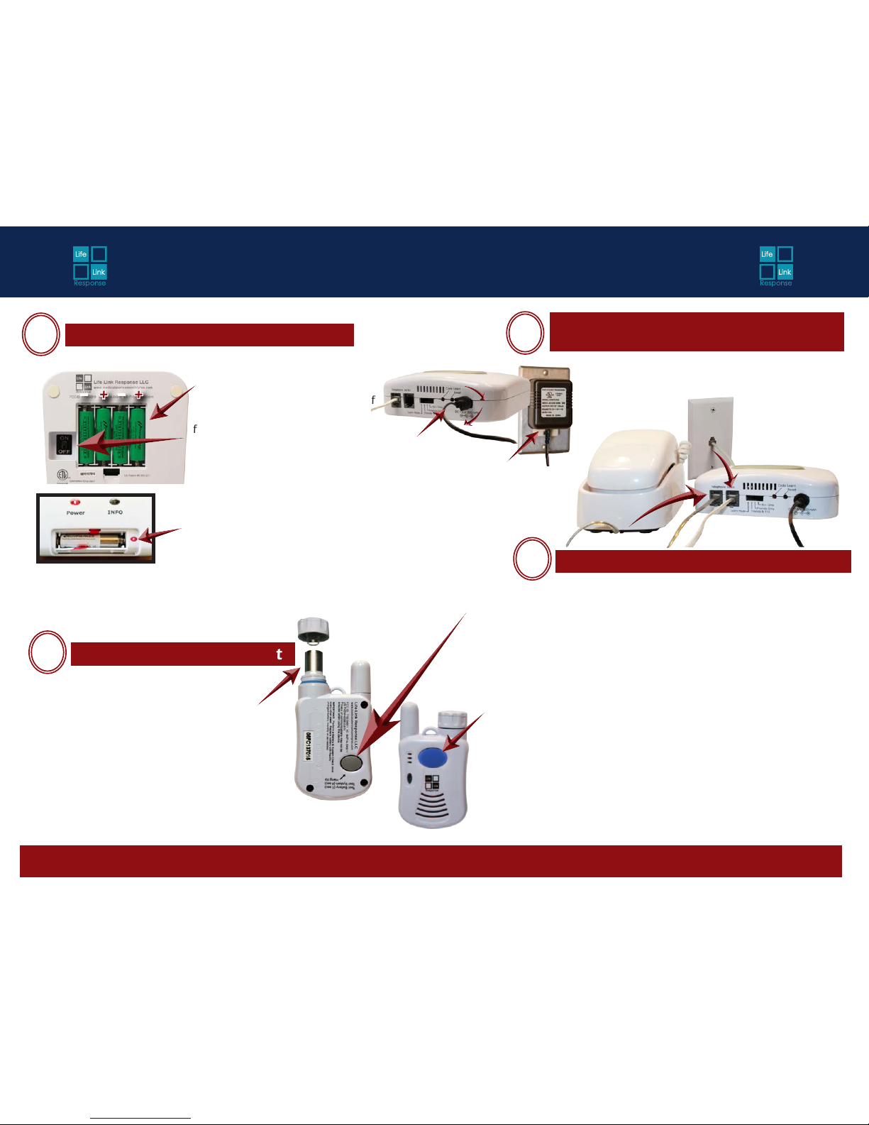
1A. Place the Green AA
Rechargeable Batteries in the
compartment on the bottom of
the base unit. Check the picture
for correct orientation.
1B. Turn ON/OFF switch to ON.
You will hear the announcement
“Running on Battery Power.” Unit
will do so until the AC Adapter
power supply is plugged in.
Step-by-Step Installation
Master
ON/OFF
Switch
+
+
_
_
RED Light = Charging
GREEN Light = Battery Charged
No Light = Defective battery or no battery installed
1C. Place one pendant battery
in the Pendant Battery Charger
on the front of the base. The
charging light key is as follows:
If you need assistance, go to www.medicalalertnomonthlyfee.com
Plug Telephone Line and Power
Cord into Wall Jacks
3
Place Battery in Pendant
2
Place Batteries in Base
1
Test the Unit
4
**Battery should standby in the pendant for
4-6 months (depending on use). We recommend
exchanging/charging the batteries monthly.
Install one pendant battery in pendant.
(When battery is properly installed,
pendant will automatically perform a
battery check. Listen for these voice
prompts every time a battery is installed.)
Pendant battery
compartment
**911 Forwarding Feature - If the contact deems the situation to be a true emergency, they simply press 911 on their keypad. The System will hang up
with them and dial 911. The person having the emergency will then be able to speak to the 911 Emergency Operator.
(OPTIONAL) Plug the
telephone into one of
the telephone jacks.
Plug the telephone
cord into the jack
and then plug
the System in to
a wall or modem
telephone jack.
Place a call:
a. Push the BLUE EMERGENCY button for 2 seconds on Pendant.
(The RED LED on the pendant should turn ON.)
b. You should hear a dial tone and dialing as it calls your contacts or
911. Several seconds later you will hear the announcement, “This
is an emergency. If you would like to continue, please press 5...”
Your contact should press 5, and all dialing will then stop.
c. Talk normally into the pendant– just like into a speaker phone.
d. At the end of the conversation, push the GRAY TEST BUTTON for
to hang up. The contact can also press 9 to hang up. (The System
will automatically hang up after 3 minutes of silence.)
Perform a System Test
a. Push GRAY test button on back of pendant for 4 seconds.
b. Listen for voice prompt from base unit:
i. “All Systems are OK – Battery is OK” is heard if the system is correctly
installed.
ii. If any other voice prompt is heard, the unit will describe the problem.
c. We recommend that you perform this System Test weekly.
A. Plug the AC Adapter
power cord into the power
jack and twist 1/4 turn
clockwise to lock.
B. Plug the AC Adapter into
an electrical outlet.
 Loading...