

LifeLink Prodigy LP2500, Prodigy Operation Manual

i
Ta b l e o f Co n T e n T s
1. CONSOLE CONTROLS AND INDICATORS ........................................................5
Console Top View ...................................................................................................5
Console Bottom View ...........................................................................................6
Console Rear View ................................................................................................. 7
Console Right Side View .....................................................................................8
Pendant Front View ...............................................................................................8
2. ADDITIONAL BASIC SETUP INFORMATION ...................................................11
Information on Local Setup and Remote Setup ....................................11
Things to Know About Pendants ..................................................................12
Things To Know About Emergency Numbers .........................................12
Examples of Effective Outgoing Recorded Messages .........................12
Things To Know About Your Recorded/Outgoing Message ............13
3. OPTIONAL FEATURES SETUP ...............................................................................15
The Primary Contact ...........................................................................................15
Test Required Interval ........................................................................................15
Setting the System Clock .................................................................................15
Automatic Test Call Setup ................................................................................15
Notification Setup ................................................................................................16
Console Low Battery Notification Setup .............................................16
Failed Pendant Notification Setup .........................................................17
Social Safety Setup ........................................................................................17
Cancel Button Confirmation Sound: Chime or Barking Dog ..........18
Override the Default 911 Emergency Number ......................................19
4. OPERATING YOUR LIFELINK PRODIGY .............................................................21
Emergency Operation ........................................................................................21
Triggering the Emergency Calling Process ........................................21
What Happens During the Process? .....................................................21
What if the Emergency Call is not Answered? .................................21
Cancelling the Emergency Call Process ..............................................21

ii
Line Seize Functionality ....................................................................................22
Direct to 911: Triggering an Emergency Call Directly to 911 .........22
Information on Two-Way Communication ...............................................22
The Notification Process ...................................................................................22
Console Low Battery Notification Process .........................................23
Failed Pendant Notification Process......................................................23
Social Safety Notification ...........................................................................23
Checking System Status ....................................................................................23
Visual Status Indicators (LED Lights) .....................................................23
Audible Status Messages ...........................................................................24
Checking System Status through a Directly-Attached Phone . . 25
Checking System Status Remotely ........................................................25
Testing Your System ............................................................................................25
Testing Strategy ..............................................................................................25
Running a Test Automatically ..................................................................26
Running a Test Manually.............................................................................26
5. THE FCC WANTS YOU TO KNOW ........................................................................27
FCC Notice ...............................................................................................................27
Radio Frequency Interference Statement.................................................27
Canadian Doc Notice..........................................................................................27
Ringer Equivalent Number ..............................................................................28
APPENDIX A: FACTORY DEFAULTS AND SPECIFICATIONS .........................29
Factory Defaults ....................................................................................................29
Technical Specifications ....................................................................................30
APPENDIX B: SAFETY ..................................................................................................31
APPENDIX C: DISCLAIMERS AND LIMITED WARRANTY ...............................33

iii
Please read this manual completely and save it for future reference.
Thank you for choosing LifeLink® Prodigy personal emergency alert system.
Prodigy is your reliable link to the outside world if you’ve fallen and cannot get
to a telephone to call for help. Prodigy is packed with well-thought-out features,
not the least of which include no activation cost, no contracts, and no monthly
fees. Specically:
We oer “simplicity out of the box” with “Simply. Smarter.” technology. •
Only two steps are required to make your Prodigy fully operational -- 1)
register at least one Pendant, and 2) program at least one emergency
phone number. Simply follow the section titled “Getting Started: Basic
Setup” , or follow the Quick Start Guide, and your system will be ready to
use in less than 15 minutes.
Up to eight (8) emergency phone numbers can be programmed to call, •
even 911.
Up to twelve (12) Pendants can be registered with the Console.•
Two-way communication capability enhances the ability to exchange •
critical information during an emergency.
Prodigy can successfully cover a home that is up to 5000 square feet. •
Range is approximately 100 feet from Pendant to Console.
Prodigy is design to seize the phone line during an emergency call, •
though there are restrictions. Please see the chapter titled “Operating
Your LifeLink Prodigy” for details.
A “Direct-to-911” function can be initiated by the user if they feel that •
their emergency may be life-threatening and warrants 911 attention.
Using the Direct-to-911 feature, the system bypasses all programmed
emergency numbers and contacts 911 directly.
Prodigy has a number of intelligent operational checks and balances •
making it the most reliable system available on the market today.
Prodigy was engineered in the United States, ensuring that only the •
highest of quality innovation, techniques, standards, approaches, and
testing is incorporated into your system.
Note that, within this Guide, the terms LifeLink, Prodigy, and LifeLink Prodigy
are used interchangeably. Each is a registered trademark or trademark of Matrix
Interactive LLC.

iv
© 2013 Matrix Interactive LLC. All rights reserved.
LifeLink Prodigy®, the LifeLink logo, and graphics are registered trademarks or
trademarks of Matrix Interactive LLC Inc. All other trademarks are the property
of their respective owners.
LIMITATION OF LIABILITY
This section contains a summary of the Disclaimers and Limited Warranty disclosed in full at the end of this Guide. It is important that you read them.
The purchaser agrees, by using this product, to the terms and conditions noted
below and in the Disclaimers and Limited Warranty. The purchaser also agrees
to read and follow all instructions and warnings on the product as well as those
documented within this Guide.
It is the sole responsibility of the purchaser and any user to assure that your
Prodigy is installed and programmed properly and that the unit is used and
maintained correctly. This includes, but is not limited to, periodic use and/
or testing to ensure that your Prodigy, including batteries, is in proper working order, that the unit is located in an appropriate location in the home, that
the electrical outlet is supplying power, and that the user has been educated
as to the operation and functionality of the product as a whole. Your Prodigy
equipment is not designed or guaranteed to prevent any loss or injury. The
Disclaimers and Limited Warranty set forth in full at the end of this Guide constitutes the terms of sale and use of the Prodigy equipment (and accessories),
and if, notwithstanding these terms of sale and use of the product, there should
arise any liability on the part of Matrix Interactive, LLC as a result of any cause
whatsoever, regardless of whether or not such loss, damage, or personal injury
was caused by or contributed to by Matrix Interactive, LLC’s negligence to any
degree or failure to perform any obligation or strict product liability, such liability
will be limited to an amount paid by the Purchaser for the product. Further, Matrix Interactive, LLC has no obligation to assure that calls are made, received, or
responded to, nor is Matrix Interactive, LLC responsible for acts, or consequences
of the acts, of those responding. Matrix Interactive, LLC provides no monitoring
service for this product. It is up to the persons at the numbers called to respond
in an appropriate manner.
Release 1.25-001
CT.TS005.003904
1. CONSOLE CONTROLS AND INDICATORS
5
1. Console ConTRols anD InDICaToRs
Your Prodigy system is made up of two main components: the system Console,
or “Console,” and the neck Pendant, or “Pendant.” Refer to the following sections/
diagrams for the location of various controls and indicators of your Prodigy
system. These controls are referenced throughout this Guide.
In general, all solid green indicator lights (LEDs) indicate that the system is
operating well. Red and/or blinking LEDs are cause for concern and indicate
that the system is in need of attention.
Console Top View
The top view of your Prodigy Console is the most important view, particularly
once your system is put into operation. You will note that the top/face of the
system is angled or tilted slightly to help ensure that the indicator LEDs are
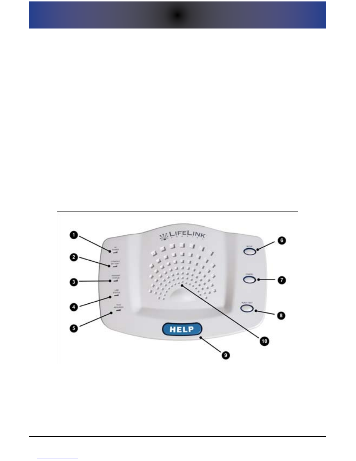
easily seen from any point within a room. The gure below shows the controls
and indicators on the top of the Console.
Console Top ViewFigure 1.
See the table below for a description of each of the indicators shown above.

6
1. CONSOLE CONTROLS AND INDICATORS
Console Top Controls and Indicators
Re f # IT e m sT a T u s /fu n C T I o n
1
AC POWER
Indicator Light
Solid Green = AC power OK.
Blinking Green = AC power out; system running
on backup battery.
2
CONSOLE BATTERY
Indicator Light
Solid Green = Console battery power OK.
Blinking Red = Console battery power is low and
replacement is needed.
3
PENDANT STATUS
Indicator Light
Solid Green = All Pendants are operating properly.
Blinking Red = At least one Pendant has reported a problem
(Pendant is not reporting or the Pendant battery is low).
4
LINE STATUS
Indicator Light
Solid Green = Phone line is OK.
Blinking Red = There is a problem with the phone
line/connection, or the phone line is in use.
5
TEST REQUIRED
Indicator Light
Solid Green = A system test is not needed at this time.
Blinking Red = A system test is recommended at this time.
6 SETUP Button
Press the SETUP button once to initiate Local Setup Mode.
Press the SETUP button twice to initiate Remote Setup Mode.
7 CANCEL Button
Press the CANCEL button to cancel any current function
(for example, the emergency calling process). This button
functions identically as the small gray CANCEL button on the
Pendant.
8 RUN A TEST Button
Press the RUN A TEST button to initiate a system test (referred
to as the “Manual System Test”).
9 HELP Button
Press the blue HELP button to initiate the emergency calling
process. This button functions identically as the blue HELP
button on the Pendant.
10 Speaker This ray-like area houses the internal speaker.
Console Bottom View
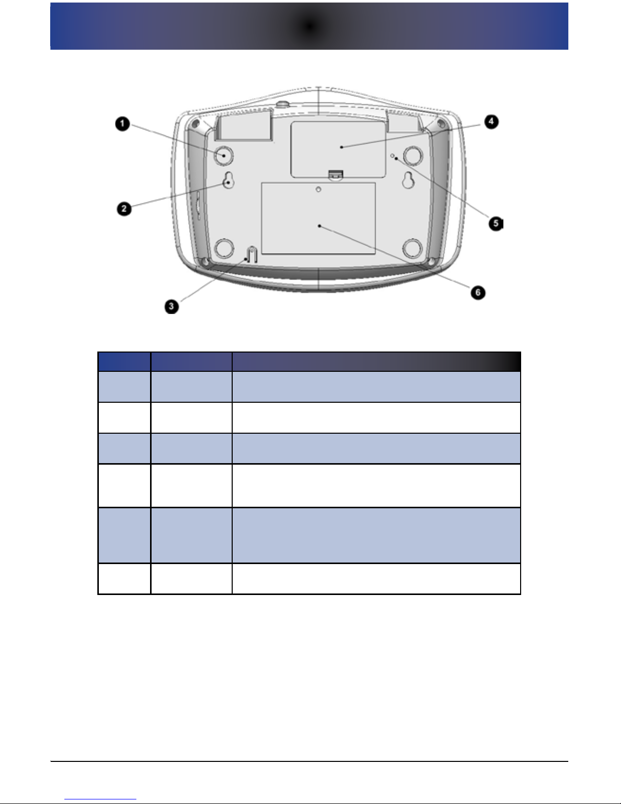
The bottom of your Prodigy Console provides access to various system
components -- the backup battery compartment, eyelets that allow you to wall
mount the system, a reset button, and other features as noted below.
1. CONSOLE CONTROLS AND INDICATORS
7
Console Bottom ViewFigure 2.
Console Bottom ControlsTable 1.
Re f # IT e m fu n C T I o n
1 Foot Pads
Rubber foot pads facilitate slide-free (padded) tabletop
installation. Table-top placement is typical.
2
Wall Mount
Eyelets
Eyelets allow you to wall mount the system if desired.
3 MIC
This is the microphone for the system that allows for two-way
communications.
4
Console
Backup Battery
Compartment
This compartment stores the 9-volt backup battery that the
Console uses in the event of an AC power outage.
5 RESET button
This button allows you to reset the system in the event that it
appears to be “frozen”. This is similar to the reboot function of
a computer. This buttons does NOT reset the system to factory
defaults, though the system clock is reset to 12:00am.
6
Informational
Sticker
General information sticker.
Console Rear View
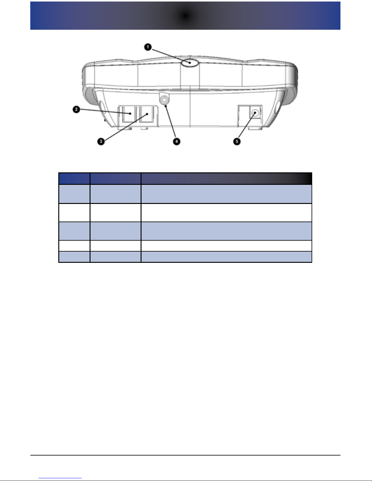
The rear of your Prodigy Console contains the power button as well as all of
the ports for connecting your Console to a phone jack, a phone (optional), AC
power, and optional external equipment.
8
1. CONSOLE CONTROLS AND INDICATORS
Console Rear ViewFigure 3.
Console Rear DescriptionsTable 2.
Re f # IT e m fu n C T I o n
1
POWER ON/OFF
Button
This is the button used to power the Console on or off.
2 TO PHONE
This is the RJ11 jack to connect your home phone to your
Prodigy Console.
3 TO WALL
This is the RJ11 jack to connect your Prodigy Console to a
telephone wall jack.
4 AUX Port Supports an optional external siren (sold separately).
5 POWER IN Supports the AC power supply to power the Console.
Console Right Side View
Located on the right hand side of the Console is the volume control knob/wheel
which allows you to control the volume level of the speaker inside your Prodigy.
The eective volume range is between 30 decibels and 80 decibels. You should
be careful not to force the knob past the extreme low and extreme high volume
levels to avoid breaking the knob and/or housing. Note that the decibel scale is
a logarithmic scale and not a linear scale.
Pendant Front View
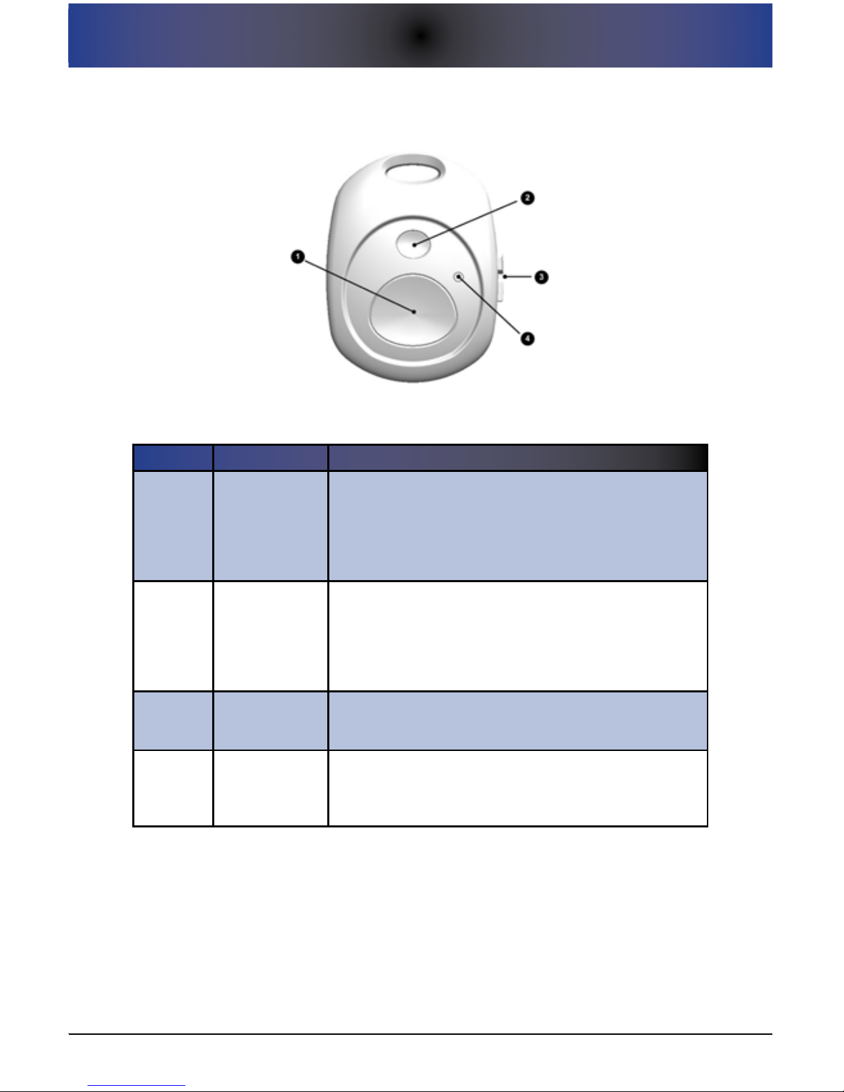
The front of the Pendant contains the controls/indicators that allow the user
to initiate the emergency call process or to cancel a previously-triggered
emergency call process. The Pendant design has been deliberately left
extremely simple with only two controls -- the large blue HELP/Emergency
button and a smaller gray CANCEL button. Each is described below.
1. CONSOLE CONTROLS AND INDICATORS
9
Pendant Figure 4.
Pendant Controls and IndicatorsTable 1.
Re f # IT e m fu n C T I o n
1 HELP Button
The large blue HELP button on the Pendant is to be
pressed to trigger the emergency calling process. As an
added feature, if this button is pressed three times within a
5-second period, Prodigy will call 911 directly, skipping all
programmed numbers. This is known as the “Direct to 911”
feature.
2 CANCEL Button
The small gray CANCEL button is to be pressed to stop/
cancel the emergency calling process. This functions
identically to the CANCEL button on the Console. You can
also use this button to test the connectivity between the
Pendant and the Console as well as the power level in the
battery within the Pendant.
3
Opposing
Thumb Tabs
The opposing thumb tabs allow for ease of opening the
Pendant for battery replacement without the need for tools.
The Pendant uses a single CR2032 (3-volt lithium) battery.
4 Signal LED
The red LED indicator illuminates after the HELP or CANCEL
buttons are pressed. This provides a visual indication to
the user that the wireless signal has been successfully
transmitted.

10
1. CONSOLE CONTROLS AND INDICATORS
2. ADDITIONAL BASIC SETUP INFORMATION
11
2. aDDITIonal basIC seTuP InfoRmaTIon
All users should start with Basic Setup for initial setup of the system as outlined
within the Quick Start Guide. Please refer to that document for information.
Then, refer to subsequent sections within this User Guide for advanced
functionality if you wish. This section provides some additional information
about the Basic Setup process.
For problems with setup, please refer to our online support page at:
www.LifelinkMedicalAlert.com/support
Information on Local Setup and Remote Setup
All setup of your system is done by using the numeric keypad on either
a directly-attached (Local Setup mode) or remote (Remote Setup mode)
telephone. The next sections describe how to enter Setup mode through either
method:
Performing Setup From a Directly-Attached Phone (Local Setup)
To perform Local Setup, you must have a phone attached to the Console.
If this is the case, simply pick up this directly-attached phone handset and
press the SETUP button on the Console.
Performing Setup Remotely (Remote Setup)
In order to use Remote Setup, the system must be connected
to a working phone line.
Remote Setup is available with your Prodigy system. Remote Setup is
benecial, for example, if the individual programming the system cannot
physically be near the device or if a directly-attached telephone is not available for local setup.
Note that, once in Setup mode, Setup will time out if a
keypress is not received from the phone within 30 seconds.
This is done to ensure that the system isn’t inadvertently left
in Setup mode. While this timeout is just an inconvenience for
Local Setup, remote users may need to re-initiate the setup
process by re-coordinating with the system owner if a timeout
occurs.
To initiate setup remotely, execute the following:
Ensure that the phone line is not in use, and press (or coordinate to 1.
have someone press) the SETUP button on the Console.
 Loading...