

LifeHealth irma User Manual
User Manual

This manual is published by Lifehealth, an EasyDx, Inc. brand, for use with
the IRMA Blood Analysis System, Model LH, Version 1.1.3 or above.
Prior to use consult sections A.3, A.4 and B.4.
IRMA® is a registered trademark of EasyDx, Inc.
The Bluetooth® word mark and logos are registered trademarks owned by
the Bluetooth SIG, Inc. and any use of such marks by LifeHealth, an EasyDx,
Inc. brand is under license. Other trademarks and trade names are those of
their respective owners.
Android™ is a trademark of Google Inc.

Table of Contents
Table of Contents
Section 1: The IRMA Blood Analysis System �����������������������������������������������������������������1�1
1.1 Getting Started ................................................................................................................................................................ 1.1
Unpack and Inspect the System .......................................................................................................................................................................1.1
Place the IRMA Tablet in the dock ....................................................................................................................................................................1.1
IRMA System Initial Language Setup ..............................................................................................................................................................1.2
Charge the IRMA System Batteries ...................................................................................................................................................................1.2
Install the Printer Paper ........................................................................................................................................................................................1.2
1.2 IRMA Blood Analysis System Components ............................................................................................................1.3
Description ...............................................................................................................................................................................................................1.3
1.3 IRMA Base ..........................................................................................................................................................................1.3
1.4 IRMA Waking and Sleeping Modes ..........................................................................................................................1.4
1.5 IRMA Battery Operation ................................................................................................................................................1.4
1.6 IRMA Cartridge Components .....................................................................................................................................1.5
1.7 IRMA Cartridge Care .....................................................................................................................................................1.5
Unpacking the IRMA Cartridges .......................................................................................................................................................................1.5
Equilibrating the IRMA Cartridges....................................................................................................................................................................1.5
1.8 IRMA Tablet .......................................................................................................................................................................1.6
Locking the IRMA Tablet into the dock. ..........................................................................................................................................................1.6
1.9 IRMA Tablet Main Menu ................................................................................................................................................1.6
1.10 IRMA Touchscreen Interface .......................................................................................................................................1.6
IRMA Controls ..........................................................................................................................................................................................................1.6
Buttons .......................................................................................................................................................................................................................1.6
Spinners .....................................................................................................................................................................................................................1.7
Checkboxes ..............................................................................................................................................................................................................1.7
Text Entry Area ........................................................................................................................................................................................................1.7
Motion Controls ......................................................................................................................................................................................................1.7
Common Screen Items .........................................................................................................................................................................................1.8
Test Screen ................................................................................................................................................................................................................1.8
Barcode Reader Screen ........................................................................................................................................................................................1.8
Keyboard Screen .....................................................................................................................................................................................................1.8
Instructional Screen...............................................................................................................................................................................................1.9
Wait Screen ............................................................................................................................................................................................................ 1.10
Settings And Review Screen ............................................................................................................................................................................ 1.10
Results Screen ....................................................................................................................................................................................................... 1.10
Message Dialog .................................................................................................................................................................................................... 1.12
PDF Viewer Screen .............................................................................................................................................................................................. 1.12
Buttons and Icons ................................................................................................................................................................................................ 1.13
1.11 IRMA Barometer ........................................................................................................................................................... 1.14
1.12 IRMA System Conventions ........................................................................................................................................ 1.14
1.13 Before Initial Testing ...................................................................................................................................................1.15
1.14 IRMA System Shipping and Long Term Storage ............................................................................................... 1.15
1.15 IRMA Intended Use ......................................................................................................................................................... 1.15
i

Table of Contents
Intended Use ......................................................................................................................................................................................................... 1.15
CLIA Complexity Classication ....................................................................................................................................................................... 1.16
Section 2: Patient Sample Analysis �������������������������������������������������������������������������������2�1
2.1 Sample Requirements ...................................................................................................................................................2.1
Capillary Requirements ........................................................................................................................................................................................2.1
Sample Size...............................................................................................................................................................................................................2.1
General Sample Collection Guidelines ...........................................................................................................................................................2.1
Blood Gas Sample Handling ...............................................................................................................................................................................2.1
Electrolyte Sample Handling ..............................................................................................................................................................................2.2
2.2 Sample Injection .............................................................................................................................................................2.2
Injecting a Syringe Sample ................................................................................................................................................................................. 2.2
Injecting a Capillary Sample ............................................................................................................................................................................... 2.3
2.3 Patient Test Procedure .................................................................................................................................................2.4
Performing a Patient Test ..................................................................................................................................................................................2.4
2.4 Test Results ........................................................................................................................................................................2.6
2.5 Additional Test Information ........................................................................................................................................2.6
All Cartridges ...........................................................................................................................................................................................................2.7
Blood Gas (BG) and Combo cartridge (CC) ....................................................................................................................................................2.9
CC and H3 ............................................................................................................................................................................................................... 2.10
Section 3: Quality Control Testing ���������������������������������������������������������������������������������3�1
3.1 IRMA Cartridges ...............................................................................................................................................................3.1
3.2 IRMA Quality Control .....................................................................................................................................................3.1
3.3 LQC Material Handling ..................................................................................................................................................3.2
LQC Materials ...........................................................................................................................................................................................................3.2
CC, BG and H3 Control Materials Procedure .................................................................................................................................................3.2
3.4 Quality Control Recommendations..........................................................................................................................3.2
3.5 Electronic Quality Control ............................................................................................................................................3.3
3.6 Running an LQC Test ...................................................................................................................................................... 3.4
3.7 LQC Test Results ............................................................................................................................................................... 3.5
3.8 Temperature Quality Control ......................................................................................................................................3.5
Section 4: Review ������������������������������������������������������������������������������������������������������������4�1
4.1 Review Options Overview ...........................................................................................................................................4.1
4.2 Search Test Results .........................................................................................................................................................4.1
Last Results - Patient .............................................................................................................................................................................................4.1
Last Results - QC .....................................................................................................................................................................................................4.2
Search Patient Results ...........................................................................................................................................................................................4.2
Search by Date: ......................................................................................................................................................................................................4.2
Search by Patient ID (PID): ..................................................................................................................................................................................4.3
Search by Operator ID (OID): .............................................................................................................................................................................4.3
Search QC Results ...................................................................................................................................................................................................4.4
Search by QC Test Type and Date: ...................................................................................................................................................................4.4
Search by QC Test Type and Operator ID (OID): ..........................................................................................................................................4.4
ii

Table of Contents
4.3 IRMA Functions ................................................................................................................................................................4.5
Software Update .....................................................................................................................................................................................................4.5
About IRMA ..............................................................................................................................................................................................................4.6
About Batteries .......................................................................................................................................................................................................4.6
About Licenses ........................................................................................................................................................................................................4.6
Save Database .........................................................................................................................................................................................................4.6
Clear Database ........................................................................................................................................................................................................4.6
Restore Database ....................................................................................................................................................................................................4.7
4.4 IRMA Logs ..........................................................................................................................................................................4.7
Error Log ....................................................................................................................................................................................................................4.7
System Log ...............................................................................................................................................................................................................4.7
Communications Log ............................................................................................................................................................................................4.7
Android Log ..............................................................................................................................................................................................................4.7
Section 5: Troubleshooting ��������������������������������������������������������������������������������������������5�1
5.1 Troubleshooting General Operational Problems ................................................................................................5.1
IRMA Base or IRMA Tablet Does Not Turn On ...............................................................................................................................................5.1
Battery Problems ....................................................................................................................................................................................................5.1
Printer Problems .....................................................................................................................................................................................................5.2
IRMA Tablet Problems ...........................................................................................................................................................................................5.2
Inconsistent Test Results ...................................................................................................................................................................................... 5.2
EQC Failures ..............................................................................................................................................................................................................5.3
Temperature Test Failures ....................................................................................................................................................................................5.3
5.2 Troubleshooting Specic Operating Problems ....................................................................................................5.4
Sensor Errors ............................................................................................................................................................................................................5.4
Procedural Errors ....................................................................................................................................................................................................5.4
Entry Errors ...............................................................................................................................................................................................................5.4
Temperature Errors ................................................................................................................................................................................................5.5
Analyzer Problems .................................................................................................................................................................................................5.5
Section 6: IRMA Component Replacement �������������������������������������������������������������������6�1
6.1 Replacing the Edge Connector ..................................................................................................................................6.1
6.2 Replacing the IRMA Base Battery ..............................................................................................................................6.2
6.3 Replacing the Printer Door ..........................................................................................................................................6.2
6.4 Replacing the Printer Module ....................................................................................................................................6.3
6.5 Replacing the Dock ........................................................................................................................................................6.4
6.6 Replacing the IRMA Tablet ........................................................................................................................................... 6.4
Section 7� Cleaning the IRMA Blood Analysis System �������������������������������������������������7�1
7.1 Cleaning Solutions .........................................................................................................................................................7.1
7.2 Cleaning the IRMA Tablet ............................................................................................................................................. 7.1
7.3 Cleaning the IRMA Base ................................................................................................................................................7.1
7.4 Cleaning the Infrared Sensor ......................................................................................................................................7.1
Section 8: IRMA System Settings �����������������������������������������������������������������������������������8�1
iii

Table of Contents
8.1 Settings Options Overview .........................................................................................................................................8.1
8.2 Operator ID Settings ......................................................................................................................................................8.2
OID Required ............................................................................................................................................................................................................8.2
Password Required ................................................................................................................................................................................................8.2
Edit OID List ..............................................................................................................................................................................................................8.2
OID on Reports ........................................................................................................................................................................................................ 8.3
OID Barcode Mask ..................................................................................................................................................................................................8.3
8.3 Patient ID Settings ..........................................................................................................................................................8.4
PID Required ............................................................................................................................................................................................................8.4
Default PID ................................................................................................................................................................................................................8.4
PID Length ................................................................................................................................................................................................................8.4
PID Entry Mask.........................................................................................................................................................................................................8.4
PID Barcode Mask ...................................................................................................................................................................................................8.5
8.4 Cartridge Settings ........................................................................................................................................................... 8.6
Cartridge Conguration .......................................................................................................................................................................................8.6
Manage Cartridge Lots .........................................................................................................................................................................................8.6
Add New Lot Entry During Testing ...................................................................................................................................................................8.7
Manage LQC Material Lots ..................................................................................................................................................................................8.7
8.5 Analyte Ranges ................................................................................................................................................................8.9
Patient/Sample Type Setup ................................................................................................................................................................................8.9
Patient Specic Reference Range .................................................................................................................................................................. 8.10
Patient Reference Range ...................................................................................................................................................................................8.10
Master Reference Range ................................................................................................................................................................................... 8.11
Master Reference Range Setup ...................................................................................................................................................................... 8.11
Reportable Ranges ............................................................................................................................................................................................. 8.12
Reportable Range Setup................................................................................................................................................................................... 8.12
8.6 QC Lockout Settings ................................................................................................................................................... 8.13
EQC Lockout Settings ........................................................................................................................................................................................ 8.13
8.7 Test Settings ................................................................................................................................................................... 8.14
Allen's Test Range ................................................................................................................................................................................................ 8.14
Hct Bypass Correlation Mode.......................................................................................................................................................................... 8.14
Hct Bypass Correlation Setup ......................................................................................................................................................................... 8.15
Physician Entry Mode ........................................................................................................................................................................................ 8.15
Manage Physician List ....................................................................................................................................................................................... 8.16
User Note Entry Mode ....................................................................................................................................................................................... 8.16
Manage User Notes List .................................................................................................................................................................................... 8.17
Units of Measure Settings ................................................................................................................................................................................ 8.17
Calculating Slope and Intercept for Hct Bypass Correlation ................................................................................................................8.18
8.8 ABG Test Settings ......................................................................................................................................................... 8.19
Oxygen Therapy Mode ...................................................................................................................................................................................... 8.19
Congure Oxygen Devices .............................................................................................................................................................................. 8.19
Congure Oxygen Ventilators ......................................................................................................................................................................... 8.20
Patient Temperature Entry ............................................................................................................................................................................... 8.21
SpO2 Source .......................................................................................................................................................................................................... 8.21
BE and HCO3 Formula .......................................................................................................................................................................................8.22
pO2 Temperature Correction .......................................................................................................................................................................... 8.22
iv

Table of Contents
Source of Hemoglobin for BE .......................................................................................................................................................................... 8.22
Backup Source of Hemoglobin....................................................................................................................................................................... 8.22
8.9 Device Settings ............................................................................................................................................................. 8.23
Congure Wi ....................................................................................................................................................................................................... 8.23
Inactivity Timeout ............................................................................................................................................................................................... 8.24
Barcode Reader Timeout .................................................................................................................................................................................. 8.24
Audible Alerts ....................................................................................................................................................................................................... 8.24
Congure IRMA Base .......................................................................................................................................................................................... 8.24
Congure IRMA Printer ......................................................................................................................................................................................8.25
Language ............................................................................................................................................................................................................... 8.26
Use Network Date and Time ............................................................................................................................................................................ 8.26
Set Date ................................................................................................................................................................................................................... 8.26
Set Time .................................................................................................................................................................................................................. 8.27
Set Time Zone ....................................................................................................................................................................................................... 8.27
Set Time Format ................................................................................................................................................................................................... 8.27
Set Date Format ................................................................................................................................................................................................... 8.27
Appendix A: Limitations and Safety Precautions ������������������������������������������������������� A�1
A.1 Limitations ........................................................................................................................................................................ A.1
A.2 Common Sources of Sampling Errors ..................................................................................................................... A.1
A.3 Interferences .................................................................................................................................................................... A.2
A.4 Safety Precautions for Blood Handling .................................................................................................................. A.3
A.5 Other Safety Precautions ............................................................................................................................................ A.3
A.6 References ........................................................................................................................................................................ A.4
Appendix B: Specications and Cartridge Information ����������������������������������������������B�1
B.1 IRMA System Specications ........................................................................................................................................B.1
B.2 Device Disposal - At End of Useful Life....................................................................................................................B.2
B.3 Directives, Safety, Emissions, and Immunity .........................................................................................................B.2
Wireless QoS & Range Requirements ..............................................................................................................................................................B.3
Wireless Security Recommendations ..............................................................................................................................................................B.3
Simplied DoC .........................................................................................................................................................................................................B.3
Warnings and Precautions: .................................................................................................................................................................................B.4
B.4 Symbol Denition ...........................................................................................................................................................B.4
B.5 Patents ................................................................................................................................................................................B.5
B.6 Cartridge/Analyte Congurations ............................................................................................................................B.5
B.7 Cartridge Storage and Equilibration Times ...........................................................................................................B.5
B.8 Reportable Ranges .........................................................................................................................................................B.5
B.9 Display Resolution ..........................................................................................................................................................B.6
B.10 Correlation Factor Limits ..............................................................................................................................................B.6
B.12 Wireless Coexistence ........................................................................................................................................................B.7
B.13 References .........................................................................................................................................................................B.7
v

Table of Contents
Appendix C: Principles of Operation �����������������������������������������������������������������������������C�1
C.1 Measurement Technology .......................................................................................................................................... C.1
C.2 Calculated Parameters ................................................................................................................................................. C.1
C.3 References ........................................................................................................................................................................ C.3
Appendix D: Performance Characteristics ������������������������������������������������������������������ D�1
D.1 Accuracy ............................................................................................................................................................................ D.1
D.2 Precision ............................................................................................................................................................................ D.1
D.3 Linearity ............................................................................................................................................................................. D.2
Appendix E: Default Settings ����������������������������������������������������������������������������������������E�1
Appendix F: Warranty �����������������������������������������������������������������������������������������������������F�1
F.1 Limited Warranty ............................................................................................................................................................. F.1
F.2 Limitation of Remedies ................................................................................................................................................. F.1
F.3 Warranty Disclaimer ....................................................................................................................................................... F. 1
vi
1 IRMA Blood Analysis System Overview
Section 1: The IRMA Blood Analysis System
This section covers general information about the IRMA Blood Analysis System and describes the
installation process.
1.1 Getting Started
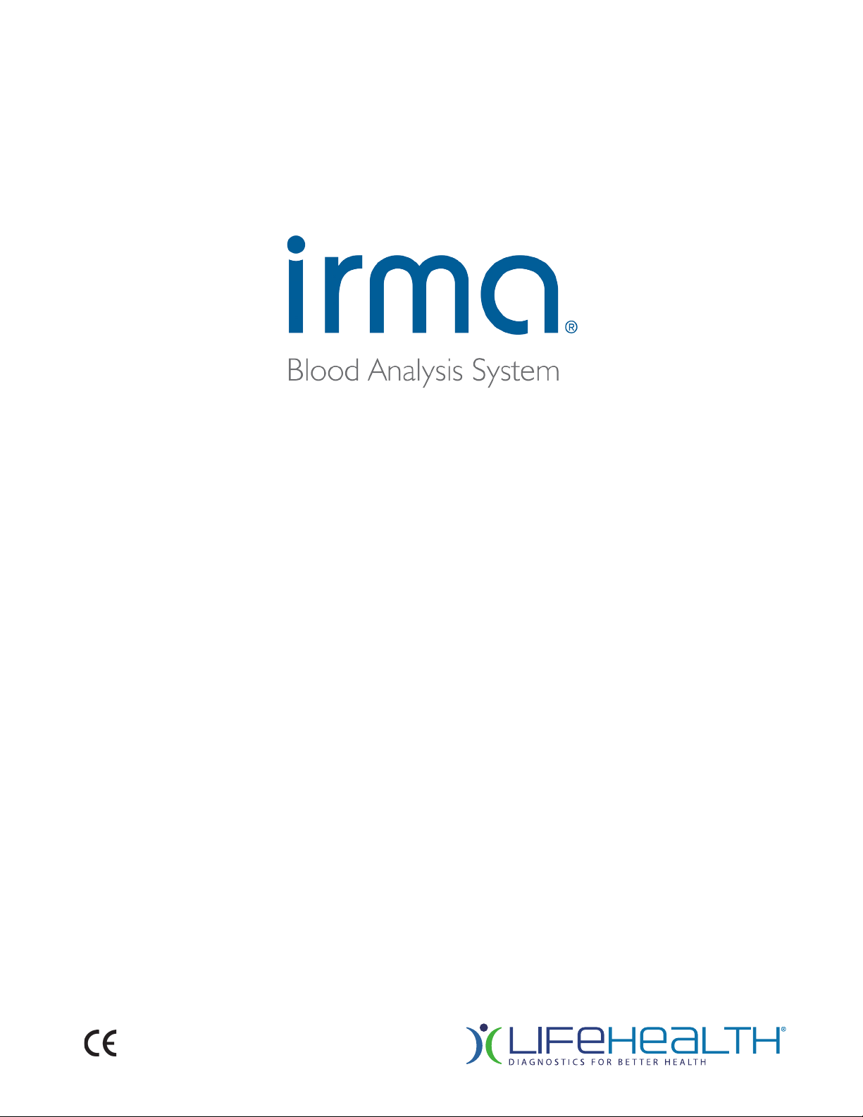
Unpack and Inspect the System
The IRMA Blood Analysis System is shipped with the
following components (Figure 1.1):
• The IRMA Base (1) with the dock (2) and removable
IRMA Tablet (3). The IRMA Tablet is packaged separately.
• AC power supply (4)
• Temperature card (5) located in the storage area
• IRMA tool (6) located in the storage area
• Thermal paper (7)
• USB 2.0 Fast Ethernet Adapter (8)
Unpack and verify that all components have been received
and inspect the components for shipping damage.
Immediately report any shipping damage to your service
provider.
If multiple IRMA Systems are received, open and assemble only one at a time. The IRMA Tablet and the IRMA base are paired
before shipment and should be kept together.
Retain one set of packaging materials. IRMA Systems requiring service by the manufacturer must be returned in the
original packaging materials. If the original packaging materials are not available, contact your service provider to obtain a
replacement.
2
1
5
4
6
8
Figure 1.1
3
7
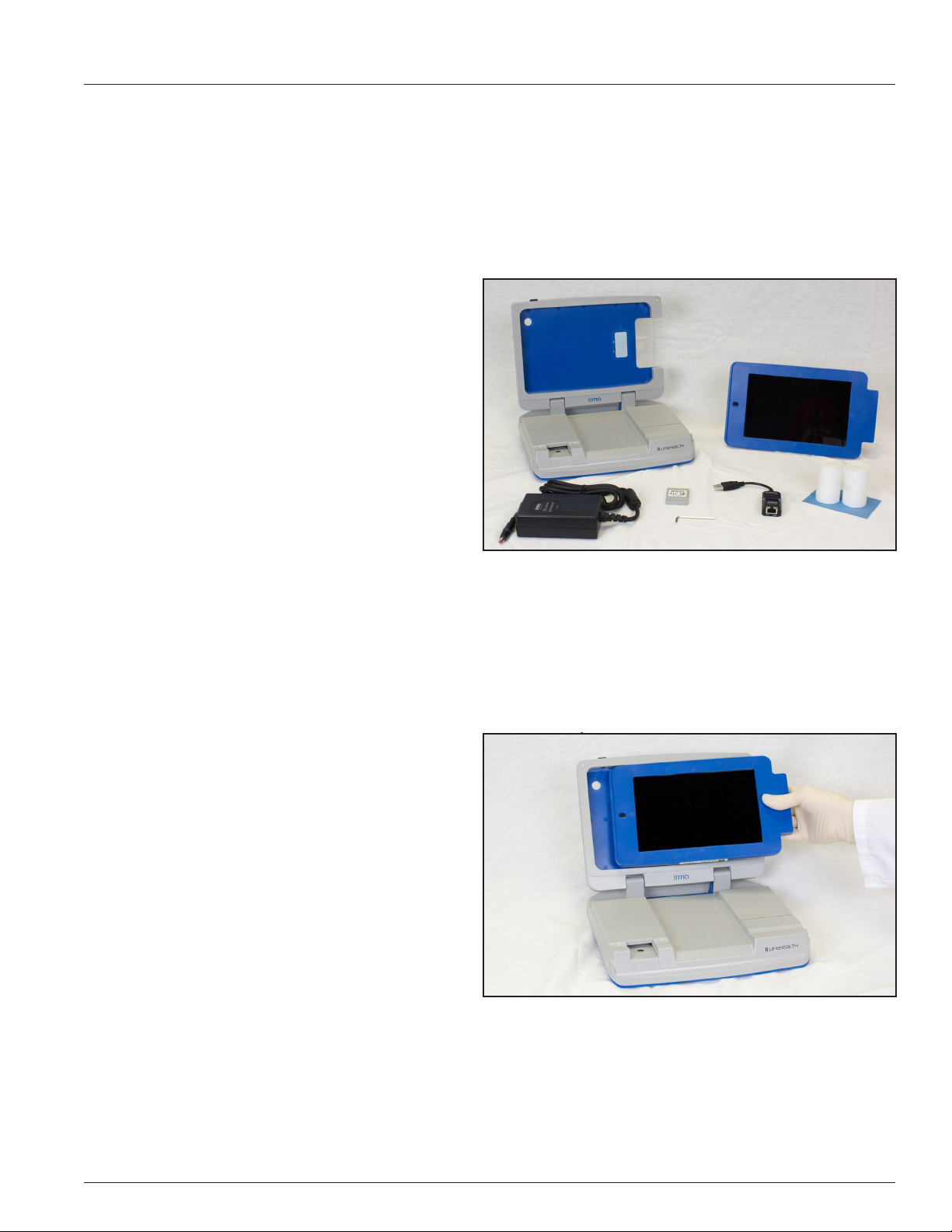
Place the IRMA Tablet in the dock
The IRMA Tablet is packaged separately. To place the IRMA
Tablet in the dock (Figure 1.2):
• Orient the IRMA Tablet so that the connector
pins (10) are on the left side.
• Locate the connector pins (11) on the dock. Holding
the IRMA Tablet at a slight angle, match the connector pins and place the IRMA Tablet in the dock.
Powerful magnets located on the right side of the
IRMA Tablet hold it in place.
• Power on the IRMA Tablet by pressing the button on
the top left edge (12) until the screen display lights
up.
11
Figure 1.2
12
10
1.1
1 IRMA Blood Analysis System Overview
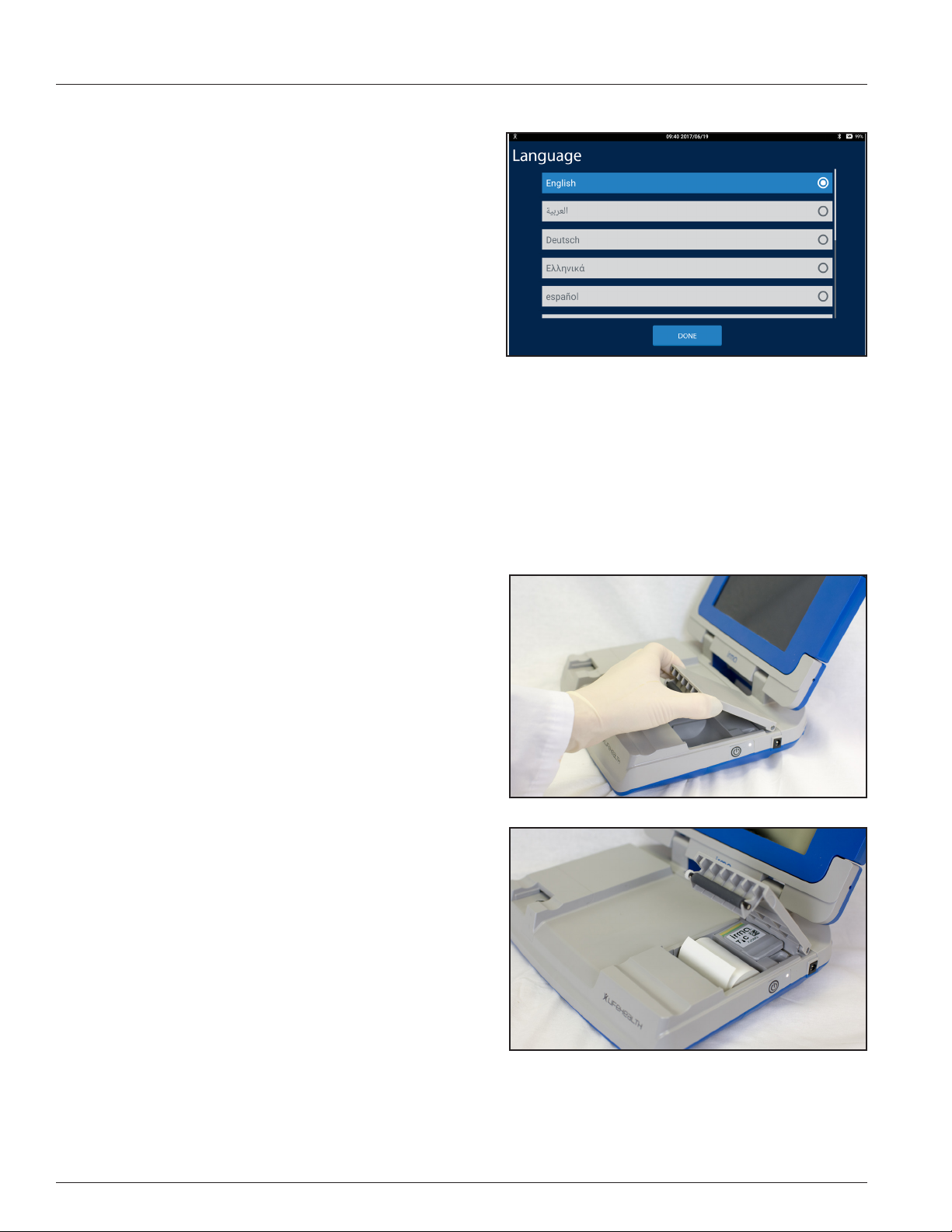
IRMA System Initial Language Setup
When the IRMA Tablet is powered on for the rst time, the Select
Language screen appears (Figure 1.3). To keep the IRMA Tablet in
English press the DONE button. To change the language, select the
desired language and press the DONE button.
Figure 1.3
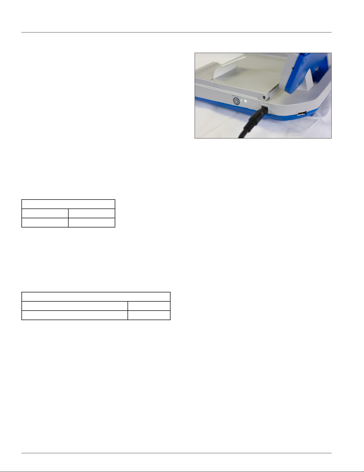
Connect the AC power supply to the IRMA Base and Power Up
Connect the power cord to the AC power supply. Place the barrel plug of the AC power supply into the barrel jack located on
the right side of the base. Plug the power cord into a power outlet.
Charge the IRMA System Batteries
When the IRMA Tablet is in the dock, the IRMA Tablet battery as well as the IRMA Base battery are charged as needed when
connected to a power source. The IRMA Base and IRMA Tablet are shipped partially charged. To fully charge the IRMA Tablet
and IRMA base, connect to a power source for 7 hours.
Install the Printer Paper
Open the door of the printer and storage compartment by placing
your ngers in the cut out area located near the front of the door and
pull up as illustrated in Figure 1.4. Place the printer paper roll in the
depressed paper compartment with the paper unrolling from the
bottom of the roll (Figure 1.5). Unroll the paper and close the door
leaving about 1 inch (2.5 cm) of paper showing.
Figure 1.4
Bring the IRMA System to Operating Temperature
The IRMA System must be at operating temperature before use.
The operating range of the IRMA Analyzer is 12 to 30° C (54 to 86°
F). If the IRMA System is exposed to a temperature outside of that
range for a signicant period of time, an instrument temperature
error message may display. The IRMA System must equilibrate at a
temperature within the temperature operating range for a minimum
of 30 minutes before testing may begin.
Figure 1.5
1.2
1 IRMA Blood Analysis System Overview
1.2 IRMA Blood Analysis System Components
Description
The major components of the IRMA System include the portable, battery-operated IRMA Base with the removable IRMA
Tablet, and IRMA cartridges that contain sensors and a calibrant. Cartridges come in a variety of analyte congurations.
Cartridges calibrate with every test using the self-contained calibrant. Instructions displayed on the IRMA Tablet guide the
user through the testing process. Patient and sample information is entered during analysis and test results are displayed in as
little as 30 seconds after sample injection. Results may be printed or transferred.
1.3 IRMA Base
The IRMA Base has the following features:
Front View (Figure 1.6)
1. IRMA Base: The IRMA Base is
paired with the IRMA Tablet
via a Bluetooth connection.
2. Integrated printer: Prints hard
copies of test results and associated information. The printer
is paired with the IRMA Tablet
via a Bluetooth connection.
3. Removable IRMA Tablet:
Guides the user through all
aspects of IRMA operation.
4. Dock: Holds and charges the
IRMA Tablet when the IRMA
System is connected to the AC
power supply.
5. AC power supply barrel jack.
6. Edge connector block: Electrically connects the cartridge to
the IRMA System.
7. Infrared (IR) sensor (recessed): Measures and
controls the sample temperature.
8. Storage area (accessed by opening the printer door) that holds the IRMA tool, temperature card and thermal paper
roll.
9. Temperature card: Used to verify that the temperature control system is operating properly. The temperature card is
found in the storage area (8).
10. IRMA tool: Used for locking the IRMA Tablet to the dock, for replacing the printer cover, and for replacing the edge
connector, printer, and/or battery, if needed. The IRMA tool is found in the storage area (8).
7
9
6
10
1
2
8
Figure 1.6
3
4
5
1.3
1 IRMA Blood Analysis System Overview
Side View (Figure 1.7)
11. Wake button.
12. Power cord connection (barrel jack).
13. USB port.
14. LED Indicators indicate whether the base is in wake or sleep
mode (white LED) and if the IRMA System requires charging
(green/amber LED) or is charging one or both of the IRMA
System's batteries.
The use of unapproved accessories may compromise safety when
using the IRMA System.
11
14
12
Figure 1.7
13
1.4 IRMA Waking and Sleeping Modes
The user can set how long the IRMA Tablet is inactive before entering sleep mode (refer to Section 8.9). To wake the IRMA
Tablet and IRMA Base, briey press the wake button on the IRMA Base. Upon waking, the Main Menu will be displayed or, if
the Operator ID feature is enabled, the Operator ID Login screen will be displayed. If the IRMA Tablet is not connected to the
IRMA Base, wake the IRMA Tablet by briey pressing the IRMA Tablet power button.
The state of the base is indicated by the white LED indicator as follows:
Base Sleep/Wake LED
Wake Mode Solid white
Sleep Mode Blinking white
Note: The IRMA Base will only enter Sleep Mode when operating on battery�
1.5 IRMA Battery Operation
When fully charged, the IRMA System can run approximately 40 to 80 tests depending on the type of cartridge used and
the amount of printing required. The battery level indicator for the IRMA System is located on the IRMA Tablet screen. The
charging time required for the IRMA Base battery or IRMA Tablet battery is approximately 7 hours.
The battery status is indicated by the green/amber LED as follows:
Base Power Indicator LED
Batteries are charging Blinking green
IRMA System requires charging Blinking amber
The IRMA Base battery is replaceable. Instructions for replacing the IRMA Base battery are found in Section 6.2. The battery in
the IRMA Tablet is not replaceable.
If the IRMA Tablet battery is completely discharged, the IRMA System requires a minimum of ten minutes of charging before it
may be used. The IRMA Tablet must be placed in the dock, and the IRMA Base must be connected to the AC power supply, in
order for its battery to charge.
CAUTION: During a cartridge test, Patient, LQC or TQC, do not plug or unplug the AC power supply into the
IRMA Base if the test is started� Plugging or unplugging the AC power supply into the IRMA Base during a test
will result in an error and the test being aborted�
1.4
1 IRMA Blood Analysis System Overview
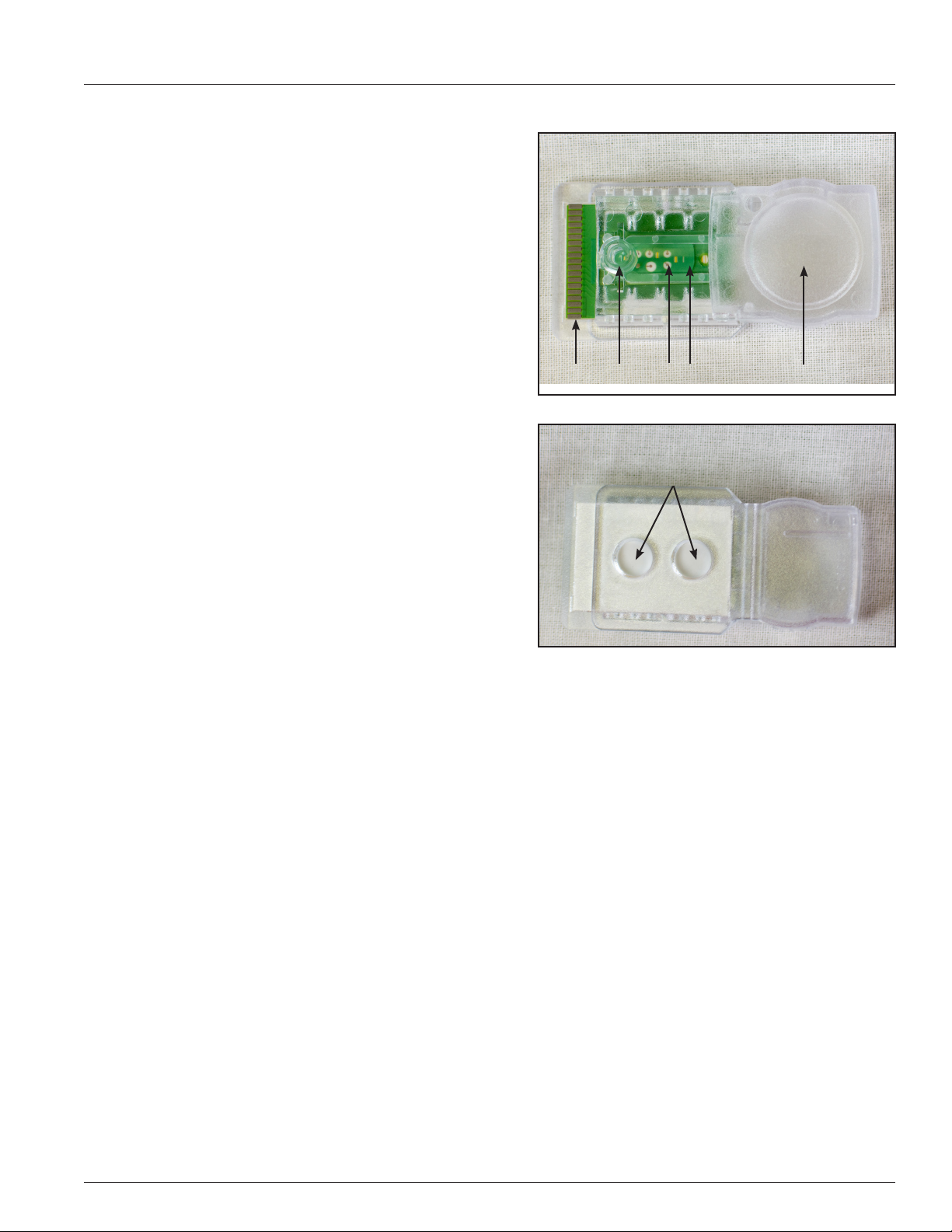
1.6 IRMA Cartridge Components
Each IRMA cartridge contains a sensor array and self-contained
calibrant (Figure 1.8). Each cartridge can perform one patient or
liquid QC test.
1. Cartridge leads: electrically connect the cartridge to the IRMA
System.
2. Luer injection port: where the sample collection device
attaches to the cartridge.
3. Sensors: measure analyte concentrations.
4. Calibrant gel: used to calibrate the sensors for cartridges that
do not have a snap cap.
5. Waste reservoir: holds a maximum volume of 5 mL.
6. Temperature monitoring access sites as shown in Figure 1.9:
where the IR sensor measures and controls sample temperature (located on the bottom of the cartridge).
1.7 IRMA Cartridge Care
Unpacking the IRMA Cartridges
IRMA cartridges are ordered, packaged, and shipped under separate
cover in an insulated shipping container. The shipping temperature
range is 0 to 50°C. Check the temperature indicators that are
included in each shipping container. Refer to the instructions that
accompany the indicators. If the temperature indicators show that
the shipping temperature range has been exceeded, do not use the
cartridges. Call your service provider for replacement cartridges.
Store the cartridges at room temperature. Refer to Appendix B,
Section B.7 for additional cartridge storage information.
1 2
3
Bottom View of Cartridges Showing
Temperature Monitoring Sites
4 5
3
6
Figure 1.8
Figure 1.9
Equilibrating the IRMA Cartridges
All cartridges must be equilibrated before use. Remove the cartridges from their shipping container and equilibrate to room
temperature in an area that has a stable temperature between 15 to 30°C (59 to 86°F) with no uctuations greater than 8°C
(14.4°F). Equilibration times vary by product and are found in Appendix B, Section B.7.
If the storage area temperature uctuations are greater than 8°C or 14.4°F, the cartridges must go through an additional
equilibration period before they can be used. Proper conditions should be documented by recording the daily minimum and
maximum storage area temperatures.
1.5
1 IRMA Blood Analysis System Overview
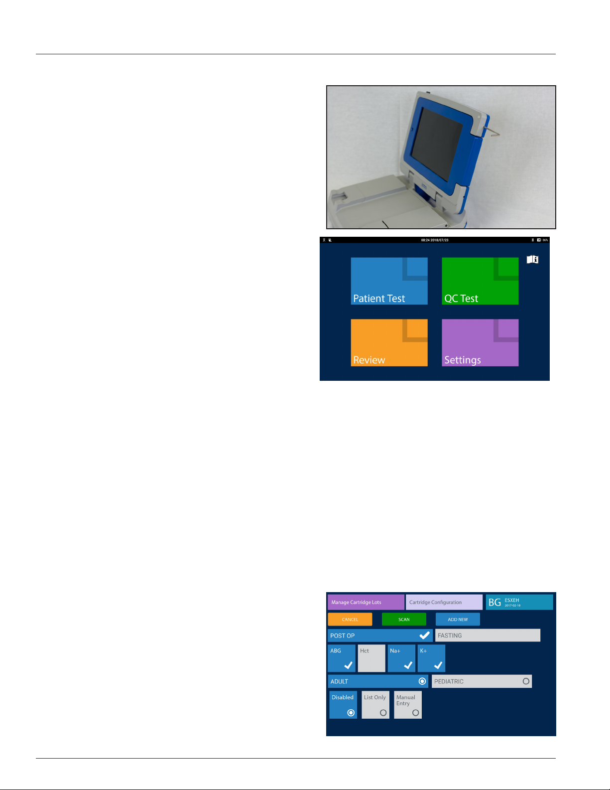
1.8 IRMA Tablet
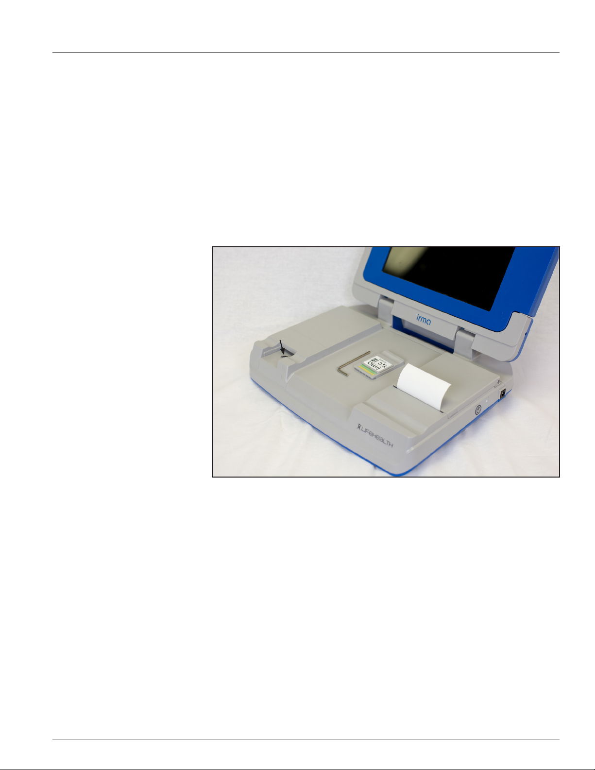
Locking the IRMA Tablet into the dock.
The IRMA Tablet can be removed from the dock when needed. To
prevent the IRMA Tablet from being removed, there are two recessed
screws located on the right side of the dock that can be deployed
into the IRMA Tablet using the IRMA tool located under the printer
door (Figure 1.10). Tighten each screw until it is nger tight. To
remove the IRMA Tablet, loosen the screws with the IRMA tool until
resistance is felt. The screws are designed so that they cannot be
removed from the dock.
1.9 IRMA Tablet Main Menu
There are ve options displayed on the Main Menu. Each are briey
described below.
• Patient Test: Used for performing a whole blood patient
sample analysis.
• QC Test: Used for performing an Electronic Quality Control
(EQC) Test, Liquid Quality Control Tests (LQC), and Temperature Verication (TQC) Test.
• Review: Used for accessing test results, viewing the logs
and other instrument functions.
• Settings: Used to congure and/or edit all IRMA System
settings including Operator ID and Patient ID settings, Analyte Ranges, Cartridge Settings, QC Lockout Settings, Test
Settings, Device Settings, and ABG Test Settings.
• Instructions For Use icon: A pdf copy of the IRMA System user manual can also be accessed from the main menu. A
searchable pdf copy of the manual may be downloaded from www.lifehealthmed.com.
Figure 1.10
1.10 IRMA Touchscreen Interface
The IRMA Tablet uses a combination of symbols, text, video, controls (buttons, spinners, text entry and checkboxes) and
motions (pressing, swiping and pinching) through which the operator interacts and controls the IRMA System to perform
testing, review test results and congure the IRMA System. The user is guided through each procedure using screens
containing easy to understand directions, buttons, graphics, and video clips (where appropriate).
IRMA Controls
The operator uses buttons, spinners, checkboxes and text entry areas to perform actions and input data into the IRMA System.
Buttons
The various types of buttons the IRMA Touchscreen Interface uses are:
• Selection: Selection buttons are used to navigate through
the IRMA Touchscreen Interface and vary in shape and color.
• Action: Action buttons are green, orange or blue and appear
at the bottom of the screen or in the keyboard area. They
perform the action of the text displayed on them.
• Multi-Select: Used to input data or congure the IRMA
System. Zero or more buttons may be selected. A multi-select
button turns blue and displays a checkmark in it when selected. When de-selected it is grey with no checkmark.
• Radio Button: Used to make a single selection. A radio button turns blue and has a dot inside the circle when selected.
When de-selected it is grey with only a circle displayed.
1.6
Spinners
The spinner control is primarily used for entering numeric data when
there are a limited number of possible entries. To use the spinner
control:
• Touch the center of the control and swipe up to change the
selection to a selection below the center position. Swipe
down to change the selection to a selection above the center
position.
• If there is no text above the center position the spinner can
only be swiped up. If there is no text below the center position the spinner can only be swpied down.
• The selection in the center blue box is the selected data
point.
Checkboxes
The checkbox control is used to turn a function on a screen on or o.
• Press the box once and a checkmark appears in it. The function is on.
• Press the box again and the checkmark is removed. The
function is o.
1 IRMA Blood Analysis System Overview
Text Entry Area
The text entry area is used with the keyboard or barcode reader. It is
described below under the Keyboard Screen.
Motion Controls
The IRMA Tablet uses a touchscreen that is responsive to the following motions controls:
• Pressing: Touch the screen with your nger or a stylus make a selection.
• Swiping: Touch the screen and then drag your nger or a stylus either up or down (scrolling) or drag it either to the
right or to the left (swiping.) When there is additional information displayed on a screen, as indicated by a thin, vertical, grey line, it is viewed by scrolling the screen.
- When multiple test records are retrieved from a search (Section 4 - Review), moving from one record to the next is
done by swiping to the left or right.
• Pinching: Touch the screen with two ngers and slide the tips of each nger together to zoom out of the text. Touch
the screen with two ngers close together and spread the tips of each nger away from the other to zoom in on the
text. The user manual is the only portion responsive to pinching.
Note: Touchscreen sensitivity varies from individual to individual and may be aected by various factors like
the amount of moisture on the skin� As a result, the touchscreen performance experienced by some operators
may be compromised� For operators that experience an ongoing issue with touchscreen responsiveness, the
use of a touchscreen stylus is recommended�
Note: The IRMA Tablet's touchscreen may be used while wearing nitrile, vinyl or latex gloves� If a glove liner
is to be worn, the use of a cotton or nylon glove liner is recommended� The use of polyester glove liners is not
recommended as they have been shown to aect the touchscreen's responsiveness�
1.7
1 IRMA Blood Analysis System Overview
Common Screen Items
Specic instructions for each section of the Main Menu (Patient Test, QC Test, Review and Settings) are contained in following
chapters. Common items to most screens are:
• Status Bar: When present, the status bar will be across the top of the screen. It displays the date and time and a series
of icons described in the Buttons and Icons section below.
• Action Buttons: Action buttons are green, orange or blue and appear at the bottom of the screen or in the keyboard
area. They perform the action of the text displayed on them.
• Keyboard Screen: The keyboard screen is used to enter alphanumeric information. It may be displayed in only twothirds of the screen or it may be displayed full screen.
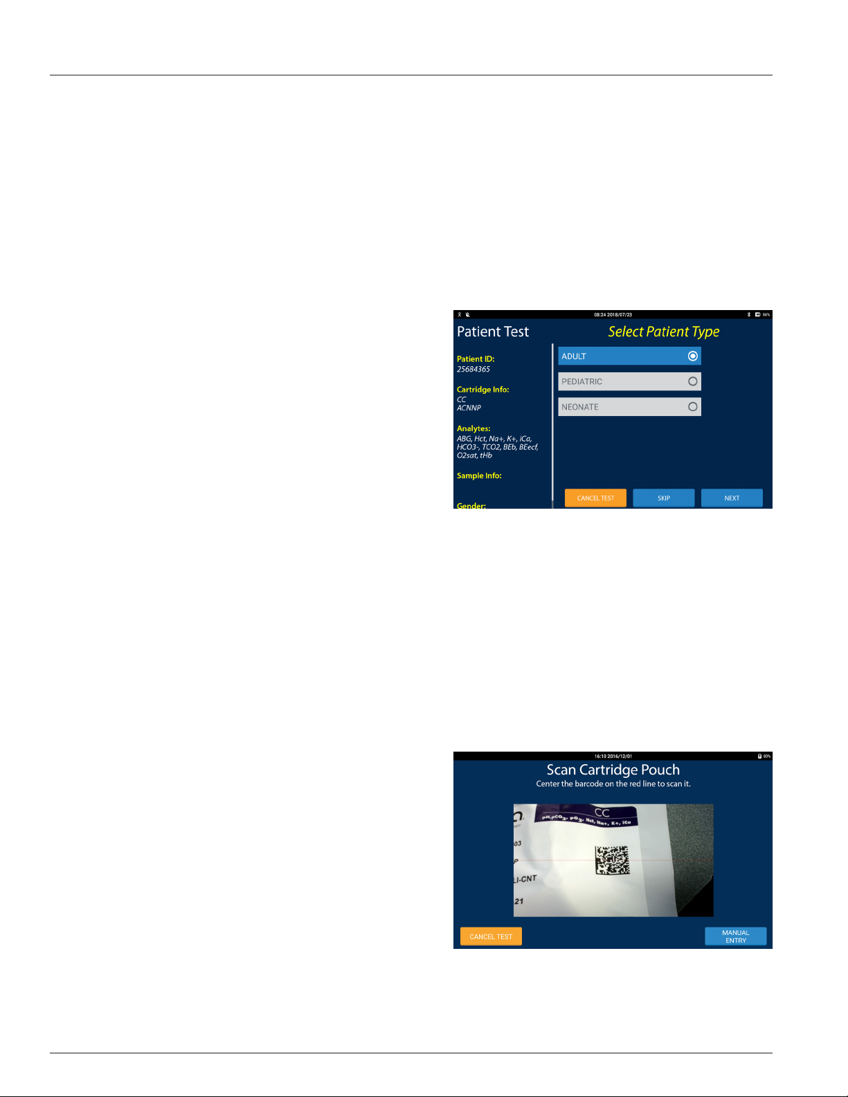
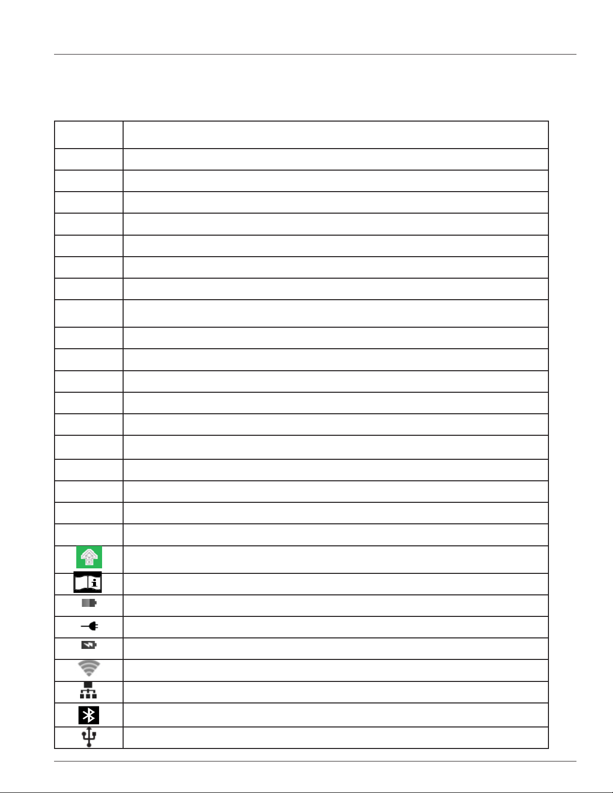
Test Screen
The Patient and QC Test screens that require operator input use a
common layout the features of which are:
• Test Progress: The left third of the screen displays informa-
tion regarding the progression of the test. The yellow, bolded
text corresponds to the title of the test screen and the white,
italicized text is the information entered on the test screen.
There may be additional information not displayed on the
screen. To view the additional information the test progress
area may be scrolled.
• Test State: The right two-thirds of the screen displays the
current state of the test or requests information to be entered
by the operator.
Barcode Reader Screen
The barcode reader is located on the back of the IRMA Tablet in the upper left hand corner. The barcode reader is used to
enter information into the IRMA Tablet. Depending on how the IRMA System is congured the barcode reader screen may be
displayed automatically or by pressing the SCAN button when available.
To use the reader, place the red cross that appears in the center of the viewnder on the barcode to be scanned. Center the
barcode in the screen area and hold it steady to assist the autofocus in detecting the barcode. If the barcode does not scan
after a few seconds, slowly move it closer or further away from the IRMA Tablet. Shadows across the barcode or dim lighting
may make the barcode more dicult to detect. The IRMA Tablet will emit a beep when a barcode is successfully scanned. The
barcode reader uses image processing technologies and is not an eye hazard.
If the barcode reader does not detect a barcode within a certain amount of time it will return to the manual entry screen. The
barcode reader timeout feature is found in Device Settings (refer to Section 8.9) and can be set from 10 seconds to 3 minutes.
The features of the barcode reader screen are:
• Scan Window: The center of the window displays the barcode imager's eld of view with a red cross overlaid on it.
• The barcode reader can read the following symbologies:
• 1D formats - Code 39, Code 93, Code 128 & Codabar
• 2D formats - QR Code & Data Matrix
Keyboard Screen
1.8
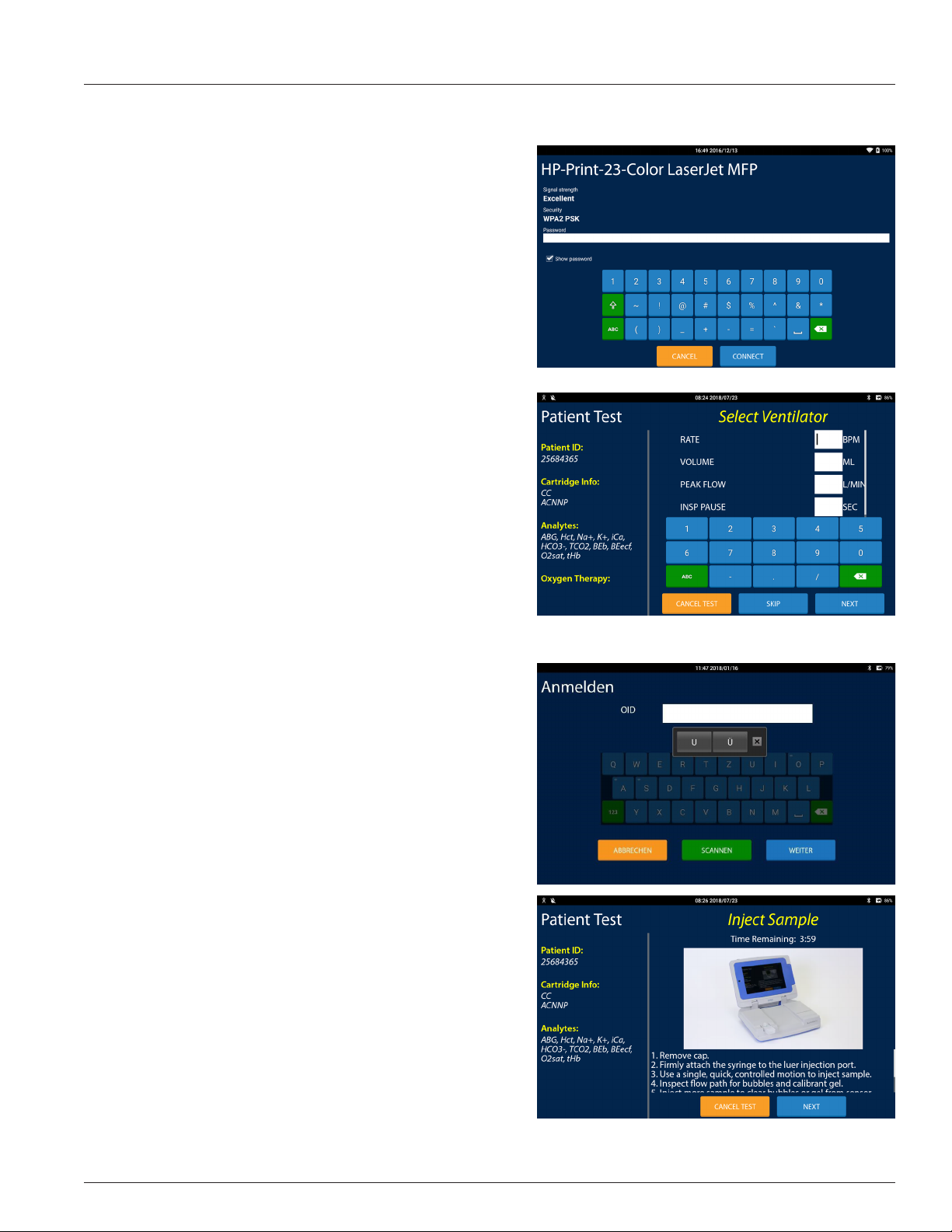
1 IRMA Blood Analysis System Overview
The features of the keyboard screen are:
• Text Entry Area: There will be one or more white, text entry
areas. To the side of the text entry area, or inside the text entry area in light grey letters, will be text explaining the information that should be entered. The input from the keyboard
buttons will be displayed in the selected text entry area. To
select a text entry area, press on it. A cursor will appear in it.
The cursor may not be moved by dragging it.
- When there are too many text entry areas to display above
the keyboard the text entry areas will scroll as a group
while the keyboard remains in its place.
• Keyboard Area: The blue keys displayed in the keyboard
area enter text in the selected text entry area when pressed.
The keys displayed are dependent on the information to be
entered in the text entry area. The green buttons are described below:
- The ABC/123 button toggles between the alpha and
numeric keyboards.
- The ?123 button displays the numeric and symbols
keyboard.
- The backspace button removes the last character in the
text entry area.
- The shift key toggles between the upper and lower case
alpha keyboard or the main and alternate numeric and
symbols keyboard.
• Alternate Keys: Depending on the keyboard, and/or the language, dierent characters may be entered using the
same key. Keys with alternate characters are distinguished
with a small dot in the upper corner of the key. To enter an
alternate character:
- Press and hold a key with a smal dot. The characters that
may be entered will be displayed. Select the desired
character by pressing it.
- Tap a key with a small dot multiple times. Tapping twice
will enter the second alternate character. Tapping three
times will enter the third alternate character, etc...
Instructional Screen
The Patient and QC Test screens use a common layout the features of
which are:
• Test Progress: Instructional screens that are displayed
during a test use the same test progress area displayed in
the Test Screen section. Instructional screens that are not
displayed during a test will not have a test progress area.
• Instructions: Instructions to guide the operator through the
operator action are displayed in the center of the screen.
• Video Loop: A short video loop showing the action to be
taken may be displayed next to the instructions.
• Timer: Some operator actions must be completed within a
dened timeframe. A countdown will be displayed indicating
the time remaining before the IRMA System will cancel the
test or action.
1.9
1 IRMA Blood Analysis System Overview
Wait Screen
When no action is required of the operator a wait screen will display
the features of which are:
• Test Progress: Wait screens that are displayed during a test
use the same test progress area displayed in the Test Screen
section. Wait screens that are not displayed during a test will
not have a test progress area.
• Progress Animation: An animation showing the approximate time until the next screen is presented is displayed in
the center of the screen.
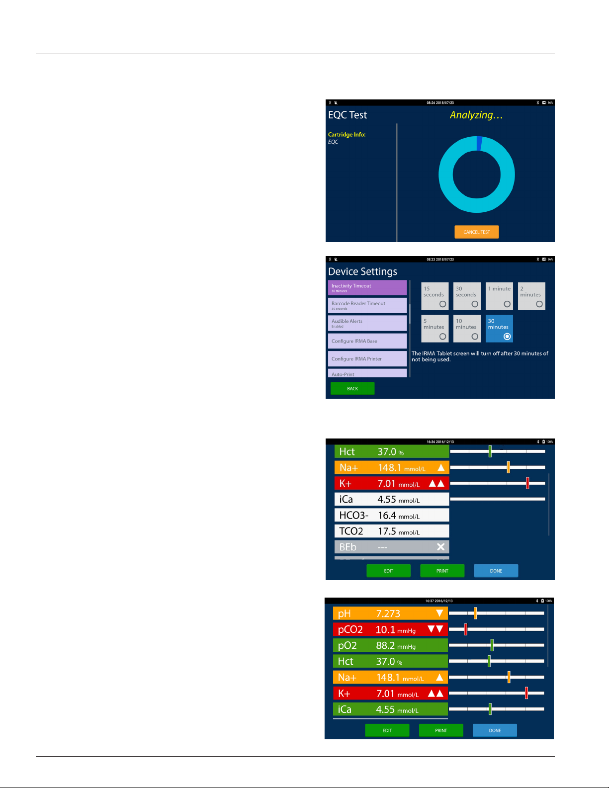
Settings And Review Screen
Most of the screens in the Settings and Review area use a common
layout the features of which are:
• Submenu list: The left third of the screen displays a column
of selection buttons (orange in Review, purple in Settings.)
Only one button may be selected at a time. The selected button is a brighter shade than the deselected buttons. When
more buttons are contained in the list than will display on the
screen, the submenu buttons are scrollable.
• Entry Area: The right two-thirds of the screen may display
informational text or, more commonly, groups of buttons,
spinners, a keyboard or another form of data input.
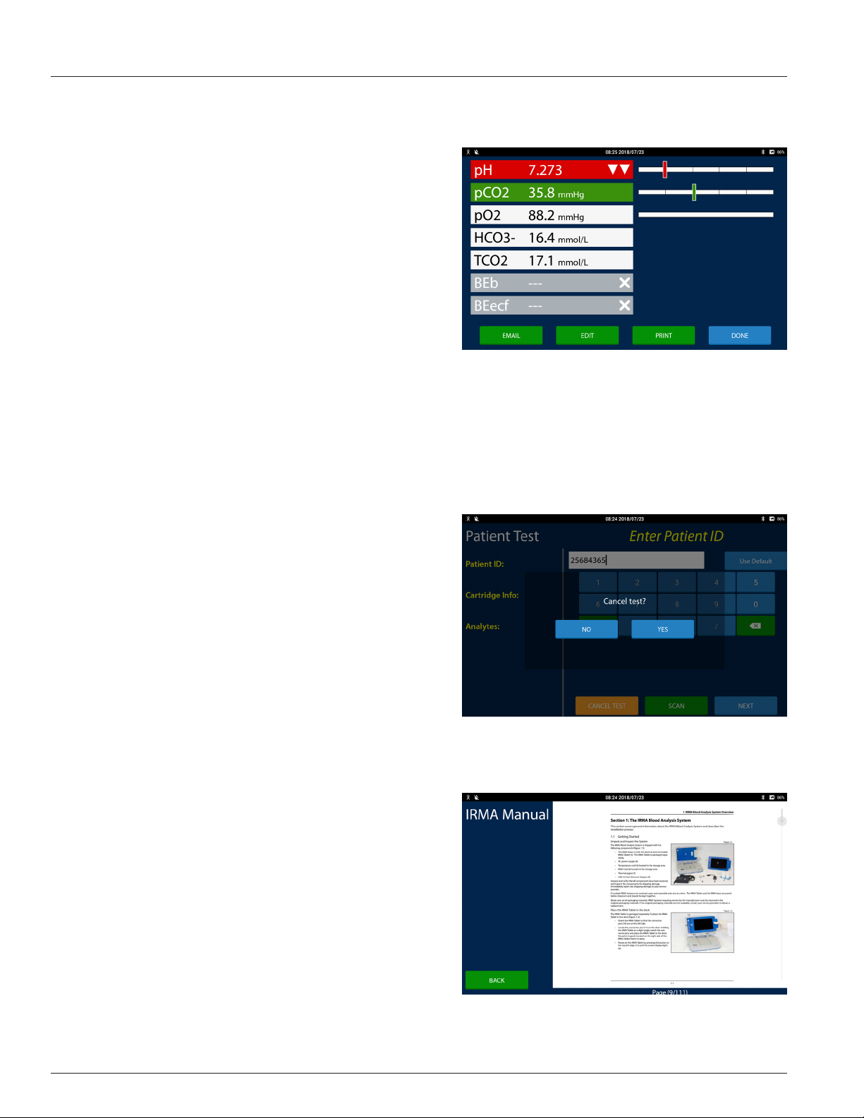
Results Screen
Patient and QC test results are displayed on the Results screen. The
Results screen is displayed at the end of a test and when test records
are retrieved in the Review area. Each measured and calculated
analyte is displayed on its own row. The features of the Results screen
are:
• Analyte Button: The analyte button displays the name of the
analyte, the analyte result, the analyte's unit of measure, and
any ags, in white text on a colored button or in black text on
a white button. The button color represents:
- Green: When the result is evaluated against a normal or
a normal and a critical reference range and is within the
normal range the analyte button is green.
- Orange: When the result is evaluated against only a
normal reference range and is outside the normal range
the analyte button is orange. When the result is evaluated
against a normal reference range and a critical reference
range and the result is outside the normal range and
inside the critical reference range the analyte button is
orange.
- Red: When the result is evaluated against a normal
reference range and a critical reference range and the
result is outside the critical range the analyte button is
red. When the result is outside of the reportable range
and is inside the IRMA System machine range, the
1.10
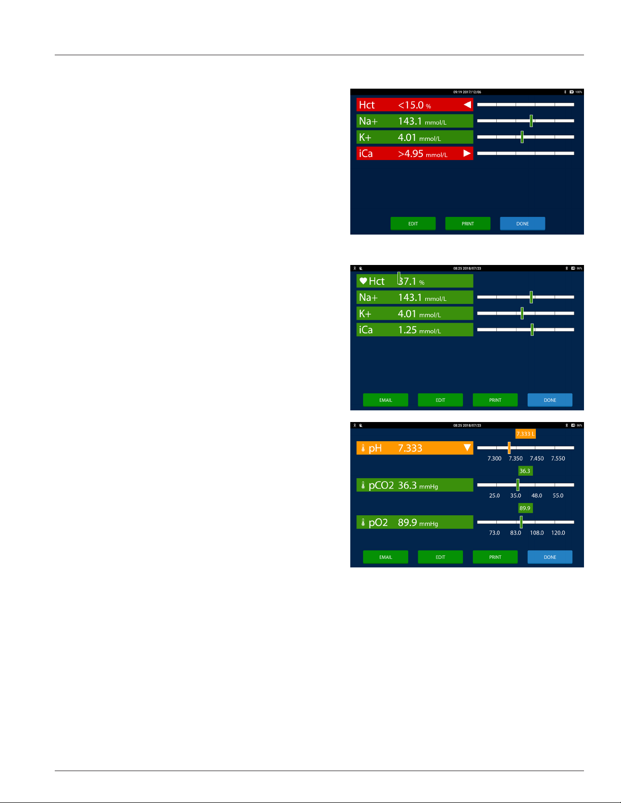
1 IRMA Blood Analysis System Overview
analyte result is reported as greater than or less than the
reportable range limit and the analyte button is red.
- White: When the result is not evaluated against a
reference range the analyte button is white.
- Grey: When the result cannot be calculated or when
the result is outside the IRMA range the result value is
suppressed. Three dashes are displayed instead of a result
value.
• The potential ags are:
- High: When the result is greater than the upper normal
reference range and less than the upper critical reference
range limit (if one is dened) a triangle pointing up is
displayed on the right hand side of the analyte button.
- Critical High: When the result is greater than the upper
critical reference range and less than the upper reportable
range limit two triangles pointing up are displayed on the
right hand side of the analyte button.
- Out of Range High: When the result is greater than the
upper reportable range and less than the upper IRMA
range a triangle pointing to the right is displayed on
the right hand side of the analyte button and a > sign is
displayed in front of the result.
- Low: When the result is less than the lower normal
reference range and greater than the lower critical
reference range limit (if one is dened) a triangle pointing
down is displayed on the right hand side of the analyte
button.
- Critical Low: When the result is less than the lower critical
reference range and greater than the lower reportable
range limit two triangles pointing down are displayed on
the right hand side of the analyte button.
- Out of Range Low: When the result is less than the lower
reportable range and greater than the lower IRMA range a
triangle pointing to the left is displayed on the right hand
side of the analyte button and a < sign is displayed in front of the result.
- Suppressed: When the result cannot be calculated or is less than the lower IRMA limit or greater than the upper
IRMA limit a X is displayed on the right hand side of the analyte button.
- Correlated Result: When On Bypass is selected a heart icon will appear on the left hand side of the analyte button
to indicate the hematocrit result was adjusted using the Hct Bypass Correlation slope and intercept values.
- Temperature Corrected Result: A thermometer icon will appear on the left hand side of the analyte button to
indicate the result was corrected for the patient temperature.
• Detail view: Press the Results Graph or the Analyte Button to toggle between the summary view of the analyte and
the detail view of the analyte. In detail view the result displays above the vertical results bar and the reference ranges
display below the bar graph.
1.11
1 IRMA Blood Analysis System Overview
• Results Graph: A bar graph of where the result falls inside its
range is displayed opposite the analyte button. The results
graph is divided into one, three or ve sections depending
on how many reference ranges are dened for the analyte.
- If both a normal and a critical reference range are dened
for the analyte, a bar with ve sections is displayed.
Results that are inside the normal range are displayed in
the center section. The sections just to the left and right of
the normal section are where the low and high results are
displayed. The outside two sections are where the critical
low and critical high results are displayed.
- If only a normal reference range is dened for the analyte,
a bar with three sections is displayed. Results that are
inside the normal range are displayed in the center section. The two outside sections are where the low and high
results are displayed.
- If there are no reference ranges dened for the analyte a bar with one section is displayed.
Note: For results that cannot have a reference range dened there is no Results Graph displayed�
Note: The vertical bar will be displayed relative to where the result falls within that reference range�
Message Dialog
If the operator attempts an action that is not allowed, or the IRMA
System needs to inform the operator of an issue requiring immediate
attention a message dialog is displayed. The message dialog is
partially transparent, covers the center of the screen and must be
addressed before returning to the screen behind it. The features of
the message dialog are:
• Instructions: Instructions to inform the operator of what is
required.
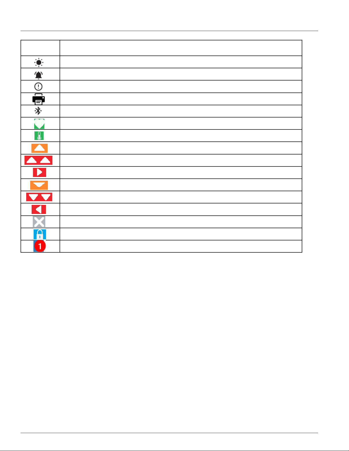
PDF Viewer Screen
Pdf formatted les are displayed in a screen with a pdf viewer. The
features of the PDF Viewer screen are:
• PDF View: The right, three-quarters of the screen is used to
display the pdf document. The document may be zoomed
by pinching. For multi-page documents scrolling will move
through the document one page at a time. On the far right
hand side of the document is a vertical line with a grey circle.
Sliding the circle up and down the vertical line will quickly
move through multiple pages of the document.
Note: The current page of the document must be at its
smallest size, fully zoomed out, in order to either scroll to
the next page or to use the slider bar�
1.12
Buttons and Icons
Below is a list of commonly used buttons and icons:
1 IRMA Blood Analysis System Overview
Button or
Icon
NEXT Proceeds to the next screen of the task
BACK Returns to the previous screen
SKIP The requested data will be blank in the database
DONE Completes the task
OK Positive acknowledgement of an informational message
CANCEL Reverts any changes or cancels an action
SCAN Displays the barcode reader screen
MANUAL
ENTRY
EDIT Opens an item or test record for editing
VIEW Opens the test result Edit screen as read only
ADD NEW Displays a screen for adding a new item
DELETE Deletes a single item
Description
Displays the manual entry screen
DELETE ALL Deletes the entire collection
PRINT Prints directly to a printer or opens the printer dialog screen
Disabled The feature will be disabled
Enabled The feature will be enabled
ABC/123 Toggles between the alpha keyboard and numeric keyboard
?123 Toggles between the numeric and symbol keyboard and the alternative symbol keyboard
Toggles between the upper and lower case keyboard or between the standard and alternate
keyboard
Displays the user manual
Indicates the amount of charge remaining in the IRMA System's batteries
Indicates the IRMA Base is connected to AC power
Indicates the IRMA System's batteries are charging
Indicates the IRMA System is connected to WiFi
Indicates the IRMA System is connected to the Wired Ethernet
Indicates the IRMA System is connected to a device via Bluetooth
Indicates a storage device is connected to the USB port
1.13
1 IRMA Blood Analysis System Overview
Button or
Icon
Description
Indicates the test has completed
Indicates the operator should view the logs
Indicates an EQC test has failed and the operator should view the logs
Indicates the IRMA System is printing a report or document
The Bluetooth Connect icon used for pairing the IRMA Tablet.
The hematocrit result is correlated
The result is corrected for patient temperature
The result is greater than the normal reference range
The result is greater than the critical reference range
The result is greater than the reportable range
The result is less than the normal reference range
The result is less than the critical reference range
The result is less than the reportable range
The result is suppressed
Testing is under QC lockout
The number of QC tests required to clear lockout
1.11 IRMA Barometer
The IRMA System utilizes two built-in barometers to measure the barometric pressure for use in calculating blood gas results.
They are calibrated by LifeHealth and do not require adjustment.
1.12 IRMA System Conventions
The IRMA System operates according to some common conventions.
• A test result is accepted when the DONE button is pressed or the IRMA Tablet enters sleep mode when the results
screen is displayed.
• The editable elds of a test record may be edited until the result is transferred to an external data sink. Printing the
test record is not considered to be a transfer to an external data sink.
Note: not all elds of a test record may be edited�
• The test record stores the information associated with it when the test was performed. For example, if Dr. Andersen
was the ordering physician when the test was performed and later Dr. Andersen's name is changed to Dr. Anderson,
the physician name in the test record will be Dr. Andersen.
Note: The only exception to this rule is an analyte's unit of measure� If the unit of measure for iCa in the IRMA
System was mmol/L when the test was run and later is changed to mg/dL, the iCa result will be reported in mg/
dL�
• In general there is no BACK button displayed during a task. If a data entry error is made, correct it by using Edit once
the task is complete.
• The SAVE button is displayed only for conguration items that require a keyboard for entry. Most conguration items
are immediately saved when changed and therefore do not require the operator to save.
1.14

1 IRMA Blood Analysis System Overview
• For conguration items added by the operator, for example Operator IDs, the convention is to delete the current item
and add a new item instead of editing the existing item.
1.13 Before Initial Testing
Prior to initial testing, complete the following:
• A QA level Operator ID (OID) is required to change most of the IRMA System settings. Identify the QA User(s) that will
supervise the setup of the IRMA System and add them to the Operator ID (OID) list. Instructions are found in Section
8.2.
• Once the QA level OIDs have been created delete the default OID, 123456. Refer to Section 8.2.
Note: If the password feature is enabled (refer to Section 8�2) passwords must be created for all OIDs after the
password feature is set to Enabled and prior to the IRMA Tablet entering sleep mode�
• Review the default IRMA System settings in Appendix E and make any adjustments. Instructions are found in
Section 8.
• Perform an EQC test as described in Section 3.5.
• Perform a TQC test as described in Section 3.7.
• Establish quality control procedures and set-up liquid controls (control type, lot, level, and limits). Refer to Sections 3
and 8.
• If a WiFi network is avaliable connect the IRMA System to the WiFi network (refer to Section 8.9). Once connected,
congure Use Network Date and Time to Enabled (refer To Section 8.9).
1.14 IRMA System Shipping and Long Term Storage
Prior to shipping the IRMA System or storing it for an extended period of time do the following.
1. Plug the AC power supply into the IRMA Base.
2. Press the wake button on the IRMA Base.
3. Remove the IRMA Tablet from the dock.
4. Press and hold the IRMA Tablet's power button until a screen is displayed asking to either Power o or Reboot. Select
Power o.
5. Temporarily set the IRMA Tablet to the side.
6. Press and hold the wake button on the IRMA Base for at least fteen seconds.
7. The two LEDs by the wake button will turn o. Release the wake button.
8. Wait for the white LED to ash.
9. Unplug the AC power supply.
10. If the IRMA System is to be placed into storage, insert the IRMA Tablet into the dock.
11. If the IRMA System is to be shipped, retrieve the original shipping materials or obtain a set from your service provider.
12. Follow the packing instructions to place the IRMA Tablet and the IRMA Base into their respective shipping inserts and
then place both of them in the shipping box.
1.15 IRMA Intended Use
Intended Use
The IRMA Blood Analysis System is intended for professional use with IRMA cartridges for the in vitro measurement of blood
gases (pCO2 and pO2), pH, sodium (Na+), potassium (K+), ionized calcium (Ca++), and hematocrit in human whole blood.
• pH, pCO2 and pO2 measurements are used in the diagnosis, monitoring and treatment of respiratory disturbances
and metabolic and respiratory based acid-base disturbances.
• Sodium (Na+) measurements are used in the diagnosis and treatment of aldosteronism, diabetes insipidus, adrenal
hypertension, Addison's disease, dehydration, inappropriate antidiuretic secretion, or other diseases involving electro-
1.15

1 IRMA Blood Analysis System Overview
lyte imbalance.
• Potassium (K+) measurements are used to monitor electrolyte balance in the diagnosis and treatment of disease
conditions characterized by low or high blood potassium levels.
• Ionized calcium (Ca++) measurements are used in the diagnosis and treatment of parathyroid disease, a variety of
bone diseases, chronic renal disease and tetany.
• Hematocrit measurements can aid in the determination and monitoring of normal or abnormal total red cell
volume status including but not limited to conditions such as anemia and erythrocytosis and blood loss related to
trauma and surgery.
CLIA Complexity Classication
The IRMA Blood Analysis System has a “moderate complexity” CLIA classication.
1.16

1 IRMA Blood Analysis System Overview
Section 2: Patient Sample Analysis
This section describes the procedure for performing a whole blood patient sample analysis using the
IRMA System, including sample requirements, sample collection, and sample handling requirements.
2.1 Sample Requirements
Acceptable Specimens Include:
• Fresh arterial or venous whole blood collected in a 1, 2, or 3 mL lithium heparin syringe. Most standard ABG syringes
are compatible with IRMA cartridges. Balanced or low-volume heparin is recommended for ionized calcium testing;
sodium heparin may be used, but sodium values may be elevated 1 to 2 mmol/L.
• Fresh capillary whole blood collected in the IRMA Capillary Collection Device, which contains balanced lithium
heparin.
• Fresh venous whole blood collected in a lithium heparin collection tube. Balanced or low-volume heparin is recommended for ionized calcium testing; sodium heparin may be used, but sodium values may be elevated 1 to 2 mmol/L.
The sample should be transferred to a non-heparinized 1, 2, or 3 mL syringe for injection into a cartridge.
Note: The following general types of syringes should not be used with IRMA cartridges:
• Frictionless or “pulsating” syringes. These syringes have plungers that will continue to travel downward after the user
has stopped injecting. This may result in a sensor error.
• Syringes that contain a mixing ball or non-dissolving disk impregnated with heparin. The ball or disk may become
lodged in the tip of the syringe, and the sample may hemolyze when it is forced through or around the plug during
injection.
• Syringes that have a non-standard Luer hub that does not t the IRMA cartridge Luer injection port.
• Samples collected in EDTA anticoagulant may not be used with the IRMA cartridge. EDTA will cause a clinically signicant error in sodium, potassium and hematocrit results and may aect other chemistry tests.
Capillary Requirements
Capillary samples must be collected in the IRMA Capillary Collection Device. Refer to the instructions for use that accompanies
the Capillary Collection Device for detailed information.
Sample Size
The minimum whole blood sample volumes are:
• 200 µL if the sample is collected in a 1 mL syringe
• 125 µL if the sample is collected in an IRMA Capillary Collection Device.
Ensure that sucient sample is collected to meet the minimum volumes required for injection into the cartridge.
General Sample Collection Guidelines
• Time sample collections to minimize delays between collection and analysis.
• Avoid drawing samples above an IV line to prevent dilution of the sample with IV uid.
• When drawing a sample from an indwelling line, back-ush and clear the line of IV uids prior to sampling to remove
anticoagulants or medications which might interfere with the test results.
• Allow the blood collection site to dry after being cleansed with alcohol to prevent hemolysis.
• Fill the collection device to the appropriate capacity. Incomplete lling may cause high heparin to blood ratios which
may lower ionized calcium results and may aect other results.
• Thoroughly mix samples collected in syringes.
• Capillary samples must be free-owing from an “arterialized” site. Avoid excessive squeezing of the puncture site to
prevent erroneous results that could result from dilution of analytes or hemolysis.
Blood Gas Sample Handling
• Expel any air present in the syringe immediately after collection and before the sample is mixed. If a portion of the
2.1

2 Patient Sample Analysis
sample must be separated for other testing, do not expose the sample to air.
• If a sample cannot be tested within 5 minutes of collection:
- Expel all air from the syringe.
- Store the blood gas sample in an ice slurry.
- Before injection, thoroughly mix the sample while the cartridge is calibrating.
Electrolyte Sample Handling
• A blood sample should be tested within 20 minutes of collection to minimize pH changes that could aect the ionized
calcium concentration.
• Do not ice samples that are to be analyzed for potassium; iced samples may hemolyze.
Preparing the Sample for Injection When Using a Syringe
• Remove any entrapped air from the syringe sample by pointing the syringe at an upward angle to allow air bubbles to
rise to the surface; expel the air, along with a small amount of blood, onto an absorbent surface.
• Check the expelled sample for blood clots. A clot usually indicates inadequate sample anticoagulation. If a clot is
injected near or over the cartridge sensors, erroneous test results or sensor errors could occur. Do not use clotted
samples.
• Mix the sample thoroughly using the following technique:
- Roll the syringe between the palms of both hands with the syringe tip pointing up.
- Invert the syringe (i.e., tip down) after 15 to 30 seconds. Continue to roll the sample, alternating syringe
orientation, until thoroughly mixed.
• When using the IRMA Capillary Collection Device, analyze the sample immediately.
2.2 Sample Injection
With each test, the cartridge automatically calibrates before the sample is injected into the cartridge. Following calibration,
the calibrant that is present in the sample path must be completely displaced by the blood sample that is being analyzed. The
sample path is the area of the cartridge that houses the sensors and must be completely lled with blood (see Figures 2-2 and
2-3). Proper sample injection technique will ensure that the calibrant is completely displaced, and that no air bubbles are
introduced during the injection step. If calibrant or bubbles are present in the sample path following the initial sample
injection from a syringe, the user can displace them by injecting additional sample from the same syringe. This prevents
sensor errors and sample loss.
Injecting a Syringe Sample
The following injection technique should be used for all syringe samples, regardless of syringe size (1, 2, or 3 mL) or sample
volume:
1. Firmly attach the syringe to the cartridge luer injection port. If the syringe does not have a luer lock tip, place the
syringe tip in the injection port and give the syringe a slight twist to rmly seat it in the port.
2. Place your ngers around the syringe so that your thumb rests on top of the plunger (Figure 2-1). Inject the sample by
depressing the syringe plunger in a single, quick, controlled motion,
similar to the motion used to press a stopwatch button. This initial
injection should be done forcefully enough to eject the calibrant from
the sample path (Figure 2-2).
3. Continue to inject until the sample path is covered (Figure 2.3). If you
can see the sample pushing the calibrant out of the sample path, you
are injecting too slowly.
Note: Do not inject the entire syringe contents (i�e�, do not push
the syringe plunger all the way down until it bottoms out) during
the initial sample injection� Doing so may hemolyze the sample�
4. Following initial sample injection, conrm that the sample path is
completely lled with sample, and that no bubbles or calibrant are
present (Figure 2-3). Bubbles or calibrant should rarely be seen if
Figure 2.1
2.2
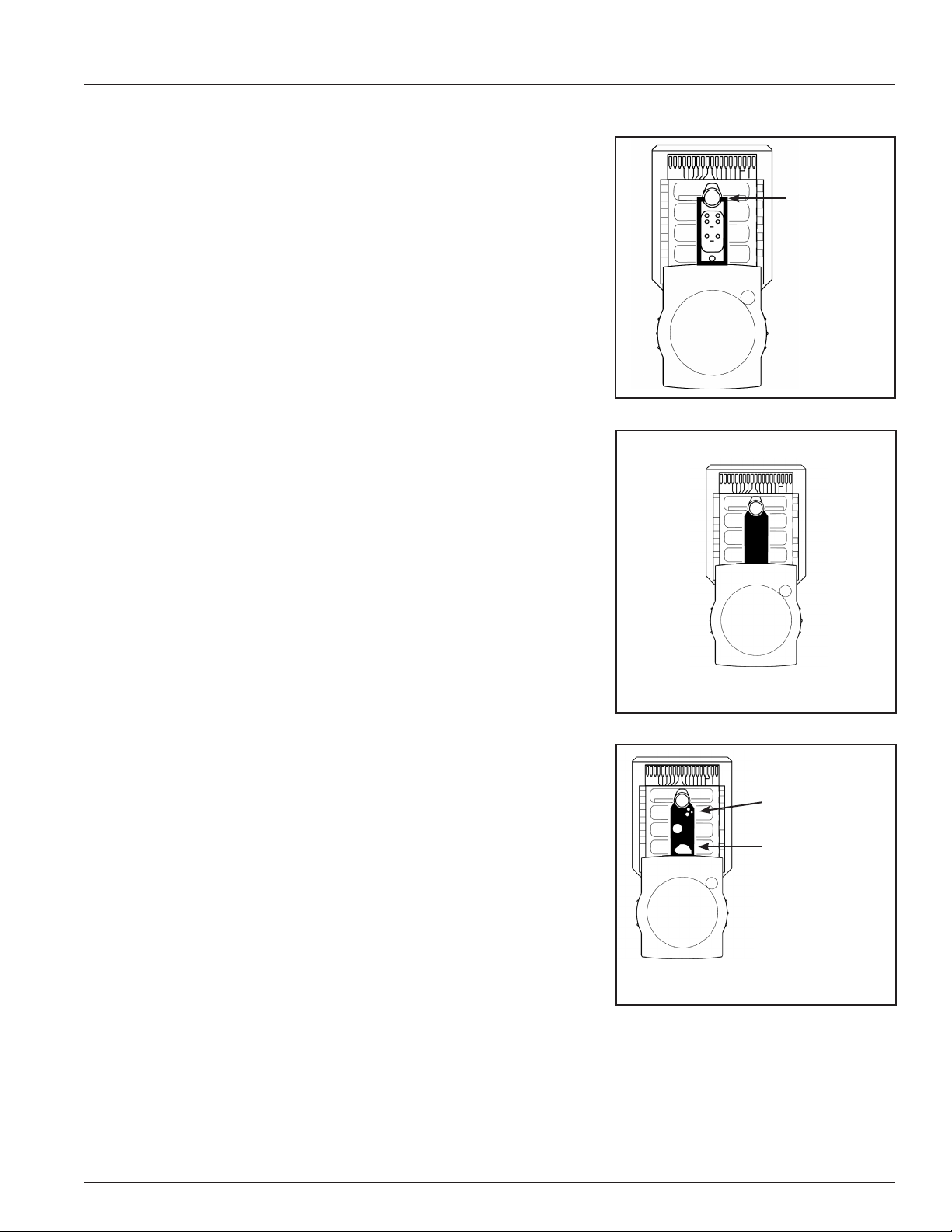
2 Patient Sample Analysis
proper injection technique is being used.
5. The sample path was designed to be easily viewed. If bubbles or calibrant
are present in the sample path and you have sucient sample remaining,
slowly inject additional sample to push them out of the sample path and
into the waste area.
6. Note: Do not pull sample from the waste area back into the sample path.
Doing so may cause inaccurate results.
7. If bubbles or calibrant do not move when additional sample is injected,
tap the top of the plunger to dislodge them, then slowly inject additional sample from the same syringe to push them into the waste area.
The entire contents of the syringe may be injected if necessary, to either
reach the minimum sample volume injection requirement (200 µL) or to
displace bubbles or calibrant.
8. If air bubbles or calibrant gel cannot be displaced from the sample path,
select cancel to stop the test, discard the single-use cartridge, and begin
again with a new cartridge.
9. Once the sample path is completely lled with a minimum of 200 µL of
sample, select CONTINUE to begin sample analysis. Leave the syringe
attached to the cartridge until the analysis is complete.
Injecting a Capillary Sample
The IRMA Capillary Collection Device must be used to collect and inject capillary
samples into IRMA cartridges. Refer to the IRMA Capillary Collection Device
package insert for instructions.
Figure 2.2
Sample path
Figure 2.3
Sample path is properly lled.
Figure 2.4
Bubbles
Calibrant
Sample path is improperly lled.
Bubbles and calibrant are present.
2.3
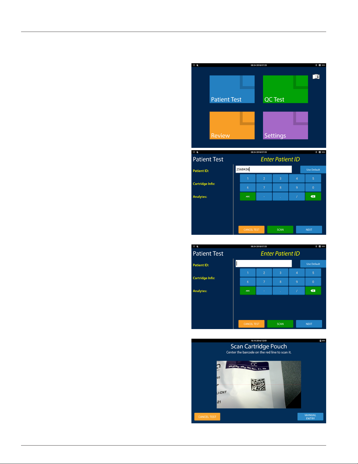
2 Patient Sample Analysis
2.3 Patient Test Procedure
Performing a Patient Test
Do not insert a cartridge into the IRMA System until instructed.
1. Press the wake button on the IRMA Base to wake the
IRMA System.
Note: If the IRMA Tablet is not in the dock press the IRMA
Tablet's power button to wake it� If the IRMA Tablet is
o the IRMA Tablet's power button must be pressed and
held until the screen comes on�
2. If the operator ID (OID) is enabled, scan or enter your operator ID. If the OID and password is enabled, both need to be
entered. Press NEXT.
3. When the Main Menu appears, select Patient Test.
4. One of the following 3 screens will appear*:
• If Patient ID is enabled, the Enter Patient ID screen will
appear. Scan or enter the Patient ID and press NEXT. If no Patient ID is available select User Default. For more information
about the User Default feature, see Section 8.3.
• If Patient Details is enabled, the Enter Patient Details screen
will appear. Enter the patient information and press NEXT.
• If Patient ID is disabled, the Scan Cartridge Pouch screen will
appear.
5. Check the expiration date on the IRMA cartridge pouch label.
The IRMA System will NOT allow testing if the cartridge is
expired.
6. Scan the 2D barcode on the cartridge pouch label or select
the lot by pressing MANUAL ENTRY. To manually select the lot
(the manual selection screens are not shown):
• Select the Product Type by choosing the correct IRMA cartridge type. The Select Cartridge Lot Code screen will appear
next.
• A listing of available lot codes to choose from will appear.
Select the correct lot code and press NEXT.
- If the lot code does not appear on the IRMA Tablet screen
see a QA User.
Note: The 2D barcode must be scanned from the IRMA
Cartridge pouch label� Scanning the 1D barcode will
result in an invalid barcode message�
*If a lock symbol appears on the Patient Test button the
instrument is in QC lockout mode� A combination of passing
EQC, TQC and/or LQC tests are required before patient
testing may be resumed� More information can be found in
Section 3 - Quality Control Testing�
2.4
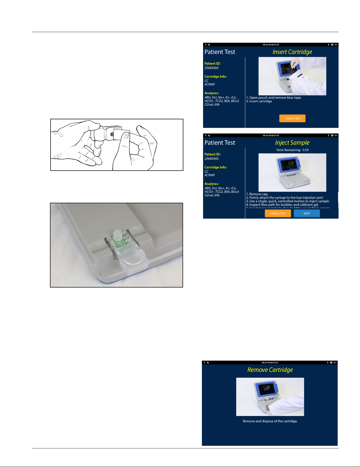
7. If the User Selects option is enabled, the Select Analytes
to Test screen will appear (screen not shown). Select the
analytes to be tested and press NEXT. If this option is not
enabled, the Insert cartridge screen appears.
8. When the Insert Cartridge screen appears, remove the
cartridge from the package.
9. Remove the protective tape from the leads on the end of the
cartridge (Figure 2.5). After removing the tape, do not touch
the leads. Do not remove the cartridge cap.
Figure 2.5
10. Insert the cartridge into the IRMA System within 15 minutes
of opening the cartridge pouch (Figure 2.6). Discard the cartridge if not inserted into the IRMA System within 15 minutes
and press CANCEL TEST.
Figure 2.6
2 Patient Sample Analysis
11. Depending on how the IRMA System is congured, and the amount of time the calibration phase takes to complete,
patient information screens (i.e Patient Type, Oxygen Therapy Information, On Bypass, etc... (screens not shown)), may
be displayed to collect this information. Refer to Section 2.5 and Section 8 for more detailed information.
12. When the Inject Sample screen appears, remove the Luer cap from the cartridge by twisting and lifting the cap. Inject
the sample using the IRMA Capillary Collection Device or syringe within 4 minutes - a count down timer is displayed
on the screen. Leave the collection device attached to the cartridge. See Section 2.2 for sample injection details.
13. Ensure that no air bubbles or calibrant gel are present in the sample path and press NEXT.
Note: If air bubbles or calibrant gel are present in the sample path, they must be removed� See Section 2�2 for
removal instructions� If the bubbles or gel cannot be removed, press CANCEL TEST, discard the IRMA cartridge,
and begin again with a new IRMA cartridge�
14. If there is still patient information to be entered the appro-
priate screens will be displayed. When all required information has been entered, and if the test is not yet complete, the
Analyzing screen will be displayed.
15. When the test is complete, the test results screen will be
displayed.
16. Remove the cartridge with the collection device attached.
Dispose of both in accordance with established guidelines
for your facility.
2.5
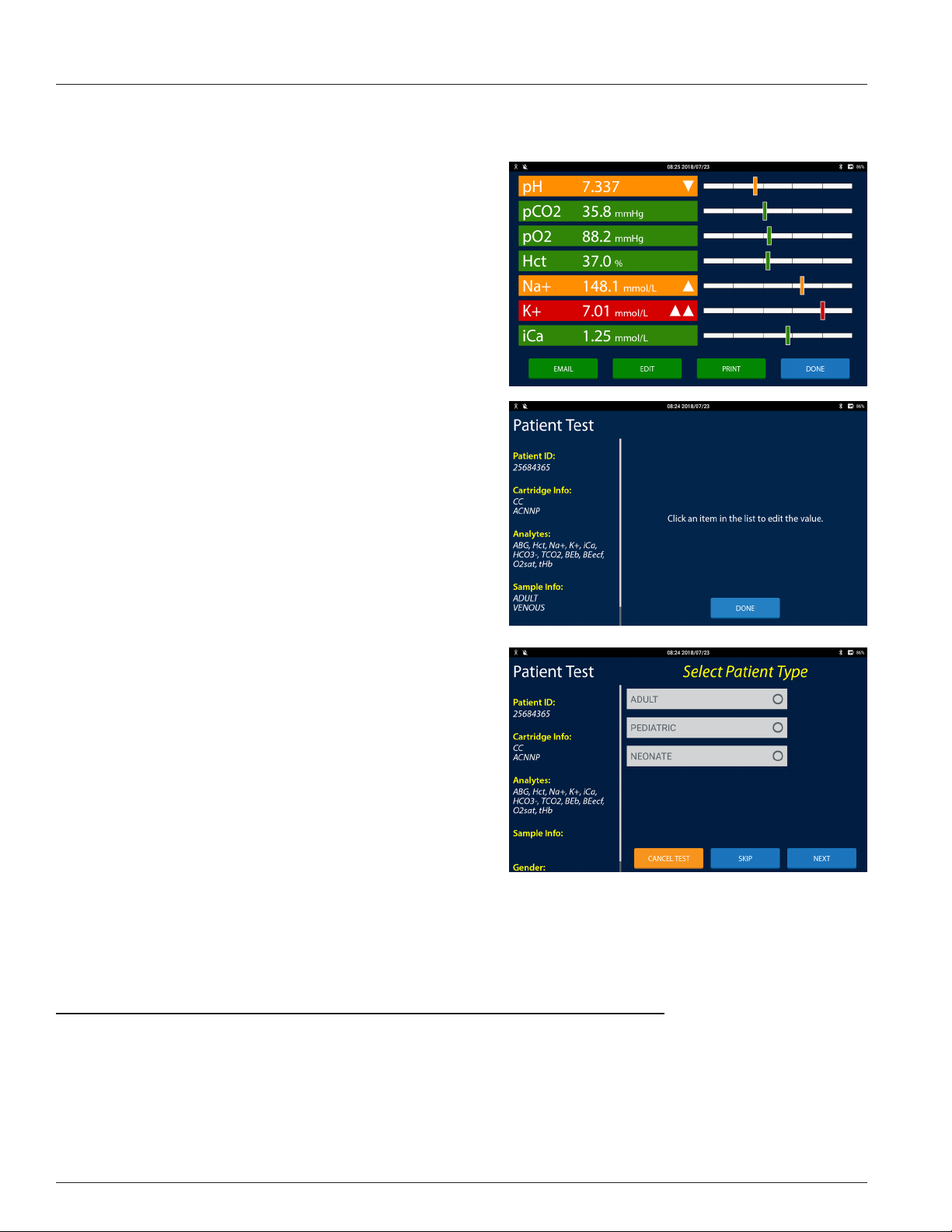
2 Patient Sample Analysis
2.4 Test Results
For information on how results are displayed on the test results screen refer to Section 1.10.
• To review patient information entered during the test press
EDIT. All of the patient test record details are displayed in
the test progress area. In the list of test details, press the test
detail to display it in the right two-thirds of the screen.
- If the test detail may not be edited it will not display in the
right two-thirds of the screen.
- If the information is incorrect edit it and press NEXT.
- To delete the information press SKIP. The entry will be
recorded as blank.
- Select another item from the list or select Done to return
to the test results screen.
• To print the test results press PRINT.
Note: The results may print in English�
• To email the test report press EMAIL.
- Select an email address from the list and press SEND.
- To email the report to an address not in the list, press the
Manual Entry Button. Enter the recipient's email address
and press ADD ITEM or press CANCEL to return to the list
of email addresses.
- To return to the results view press DONE.
Note: The Email button only appears if the email feature
has been congured (see Section 8�9)�
Note: The Manual Entry button only appears if the email
feature has been congured to allow the manual entry of
email addresses (see Section 8�9)�
Note: Any manually entered email address will remain
in the list until the Done button is pressed� It will not be
added to the congured list of email addresses�
• To accept the test and return to the Main Menu press DONE.
Note: If the cartridge has not been removed the Remove
Cartridge screen will be displayed�
2.5 Additional Test Information
Additional patient test information may be entered if congured in the Settings Menu (refer to Sections 8.5, 8.7 and 8.8). The
additional patient test information is listed below by IRMA cartridge type.
All Cartridges
Patient Type Oxygen Therapy Information Bypass Status
Patient Gender Patient Temperature
Sample Type Hemoglobin
Sample Site and Subsite SpO
Allen's Test
Ordering Physician
Patient Notes
Blood Gas (BG) and
Combo Cartridge (CC)
2
CC and H3
2.6
 Loading...