

Page 1
8215 MULTI-PRESS
Part # 6875601
ASSEMBLY INSTRUCTIONS
Revision:3/17/001
Page 2
IMPORTANT NOTES
Please note:
* Thank you for purchasing the LIFE FITNESS 8215 MULTI-PRESS. Please read these instruc-
tions thoroughly and keep them for future reference. This product must be assembled on a flat,
level surface to assure its proper function.
* We recommend cleaning your product (pads and frame) on a regular basis, using warm soapy
water. Touch-up paint can be purchased from your LIFE FITNESS customer service representative at (800) 328-9714.
There is a risk assumed by individuals who use this type of equipment. To minimize risk, please
follow these rules:
1. Inspect equipment daily. Tighten all loose connections and replace worn parts immediately.
Failure to do so may result in serious injury.
2. Do not allow minors or children to play on or around this equipment.
3. Exercise with care to avoid injury.
4. If unsure of proper use of equipment, call your local LIFE FITNESS STRENGTH distributor or
call the LIFE FITNESS STRENGTH customer service department at (800) 328-9714.
5. Consult your physician before beginning any exercise program.
Tools Required for Assembly
* Rubber mallet or hammer
* 3/4” wrench, 9/16” wrench
* Ratchet with 3/4” and 9/16” sockets
* 5/32”, 3/16”, 7/32” Allen wrenches
* Adjustable wrench
* Tape measure
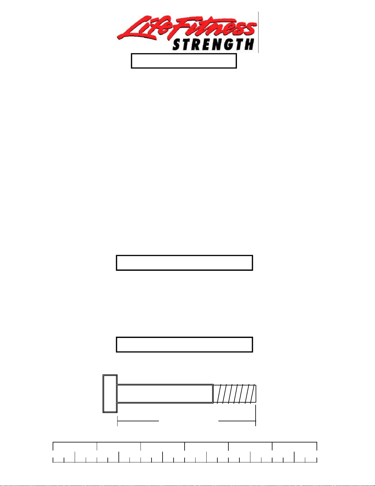
Bolt Length Ruler
NOTE: BOLT LENGTH IS MEASURED FROM THE UNDERSIDE OF THE HEAD OF THE BOLT.
BOLT LENGTH
BOLT LENGTH RULER:
1/2 1/2 1/2 1/2 1/2 1/2
0
1
2
3 4 5
2
6
Page 3

PARTS LIST
KEY
1
2
3
4
5
6
7
8
9
10
11
12
13
14
15
16
17
18
19
20
21
22
23
24
25
26
27
28
29
PART #
6795203
6784303
6755602
6755903
6878202
6783403
6781303
6784703
6784103
6624302
6624203
6651602
6780304
6780004
6791102
6214501
6284501
6714601
3116101
6782301
6784601
6382301
3108002
3109602
3118401
6757701
3203501
3103302
3202105
DESCRIPTION
TOWER
PRESS BASE
WOLFF SLEEVE
PRESS ARM
PRESS ARM ADJUST
LOWER SUPPORT
TOWER BRACE
UPPER SUPPORT
PRESS FRAME
BACK PAD ANGLE RIGHT
BACK PAD ANGLE LEFT
15-1/2” PLATE
BACK PAD
SEAT PAD
SHROUD
WEIGHT PLATE
WEIGHT STACK SHAFT
HEAD PLATE
4-1/2" PULLEY
63-1/2” GUIDE ROD
217-3/4" CABLE
WEIGHT PLATE BUSHING 10 CT
WEIGHT STACK CUSHION
1/2” PAL NUT
4” VINYL CAP
2-7/8 X 1” CABLE CLIP
PILLOW BLOCK
13/16” SHAFT COLLAR
1/2 X 7-1/2” BOLT
QTY
1
1
1
1
1
1
1
1
1
1
1
2
1
1
1
20
1
1
8
2
1
4
2
1
1
1
2
2
1
KEY
30
31
32
33
34
35
36
37
38
39
40
41
42
43
44
45
46
47
48
49
50
51
52
53
54
55
56
57
PART #
3202107
3202103
3102910
3202101
3102905
3102915
3108404
3102922
3102933
3102901
3102909
3102502
3102501
3102801
3102804
3102802
6406401
6466901
6412001
6214401
6619301
6020601
6480301
6122702
6703801
6189501
6868702
6827001
DESCRIPTION
1/2 X 6-1/2" BOLT
1/2 X 4" BOLT
1/2 X 3" BOLT
1/2 X 1-1/4” BOLT
3/8 X 3-3/4” BOLT
3/8 X 3-1/4" BOLT
3/8 X 3” FLAT HEAD BOLT
3/8 X 2-3/4" BOLT
3/8 X 2" BOLT
3/8 X 1-1/4” BOLT
3/8 X 1" BUTTON HEAD
1/2" WASHER
3/8" WASHER
1/2" LOCK NUT
1/2” LOW HEIGHT LOCK NUT
3/8" LOCK NUT
HINGE TAB
1/2" SPRING PIN
3/8" SPRING PIN
SELECTOR PIN
U-PIN
1/2" FLANGE BEARING
3/8” FLANGE SPACER
1/2” SPACER
WEIGHT STACK LABEL LBS.
WEIGHT STACK LABEL (1-25)
1/4 X 8” PLATE
2-7/8 X 2-1/4” CABLE CLIP
QTY
1
6
5
2
2
4
2
6
7
7
4
16
15
11
3
21
2
1
1
1
1
2
6
2
1
1
1
2
3
Page 4
1
32 1/2 X 3”
41
31 1/2 X 4”
8
43
43
41
1/2 X 3” 32
41
43
6
43
41
2
31 1/2 X 4”
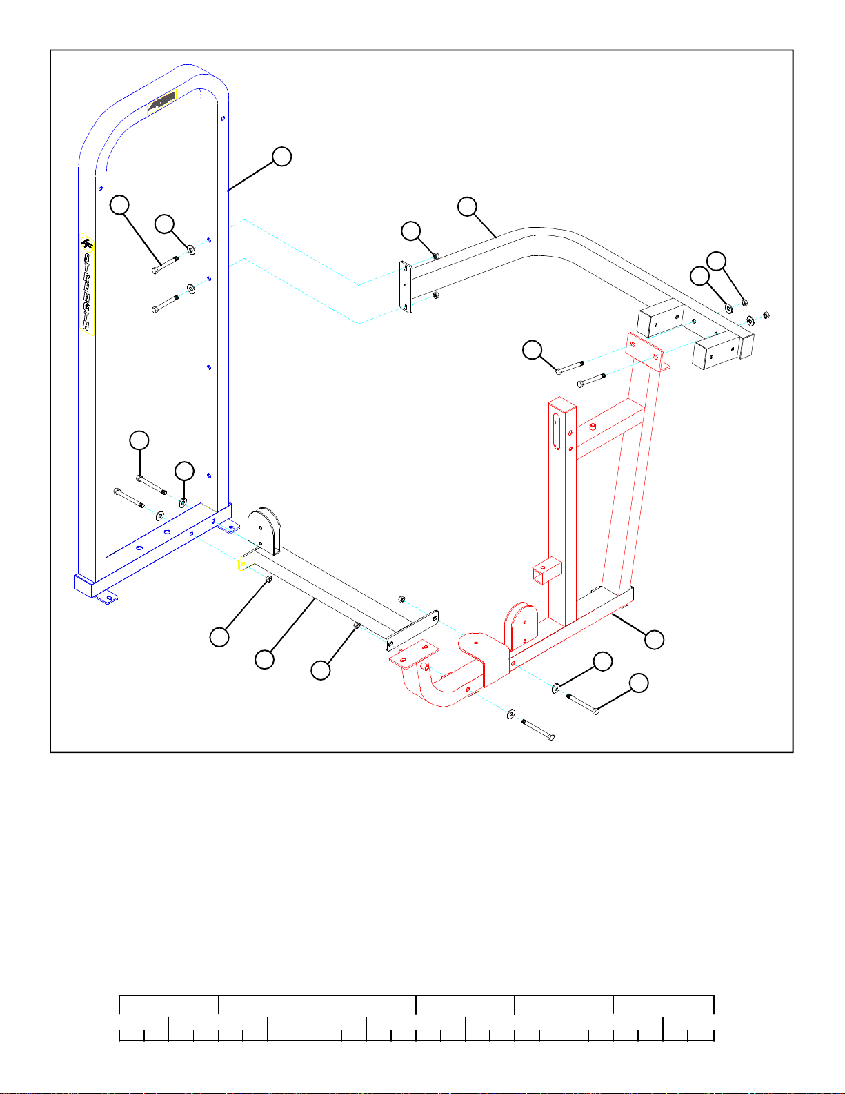
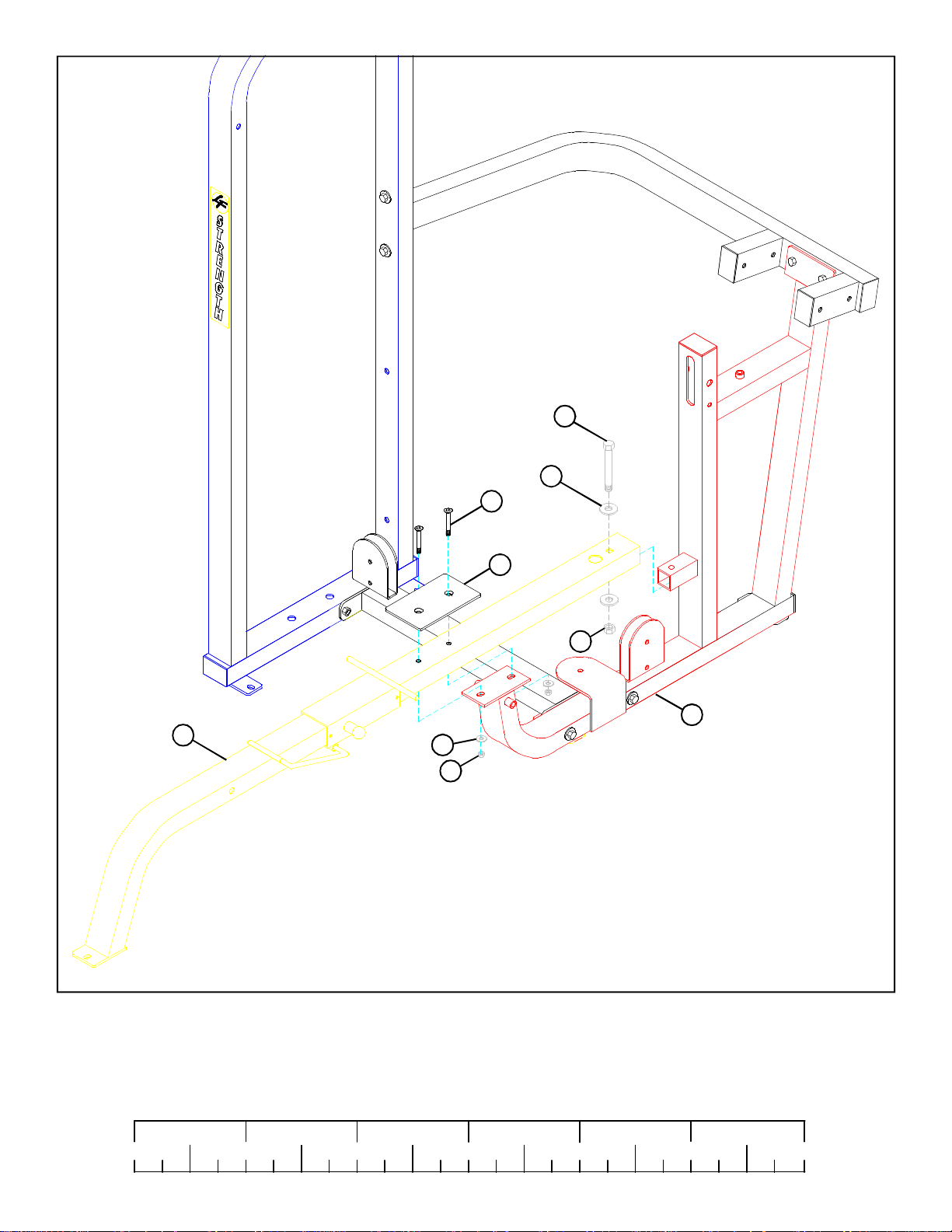
FIGURE 1
STEP 1:
• LOOSELY assemble LOWER SUPPORT (6) to the TOWER (1) and PRESS FRAME (2) using four 1/2 X 4” BOLTS (31), four
1/2” WASHERS (41), and three 1/2” LOCK NUTS (43). See FIGURE 1.
• LOOSELY assemble UPPER SUPPORT (8) to the TOWER (1) and PRESS FRAME (2) using four 1/2 X 3” BOLTS (32), four
1/2” WASHERS (41) and four 1/2” LOCK NUTS (43). See FIGURE 1.
• SECURELY TIGHTEN THE FRAME CONNECTIONS IN THE FOLLOWING ORDER:
1. LOWER SUPPORT (6) to the TOWER (1) and PRESS FRAME (2).
2. UPPER SUPPORT (8) to the TOWER (1) and PRESS FRAME (2).
1/2 1/2 1/2 1/2 1/2 1/2
0
1
2
3 4 5
6
4
Page 5
3
24
48
25
50
9
FIGURE 2
STEP 2:
• SECURELY assemble one 3/8” SPRING PIN (48) to the WOLFF SLEEVE (3) as shown in FIGURE 2. (IMPORTANT! Tighten nut of
SPRING PIN completely.)
• Attach one U-PIN (50) to the WOLFF SLEEVE (3) using one 1/2” PAL NUT (24). Slide one 4” VINYL CAP (25) onto the U-PIN (50) as
shown in FIGURE 2.
• Pull back on SPRING PIN and CAREFULLY slide the assembled WOLFF SLEEVE (3) onto the PRESS FRAME (9) until the SPRING
PIN engages in one of the holes. See FIGURE 2.
5
Page 6
1/2 X 3” 32
41
36 3/8 X 3”
56
43
9
42
45
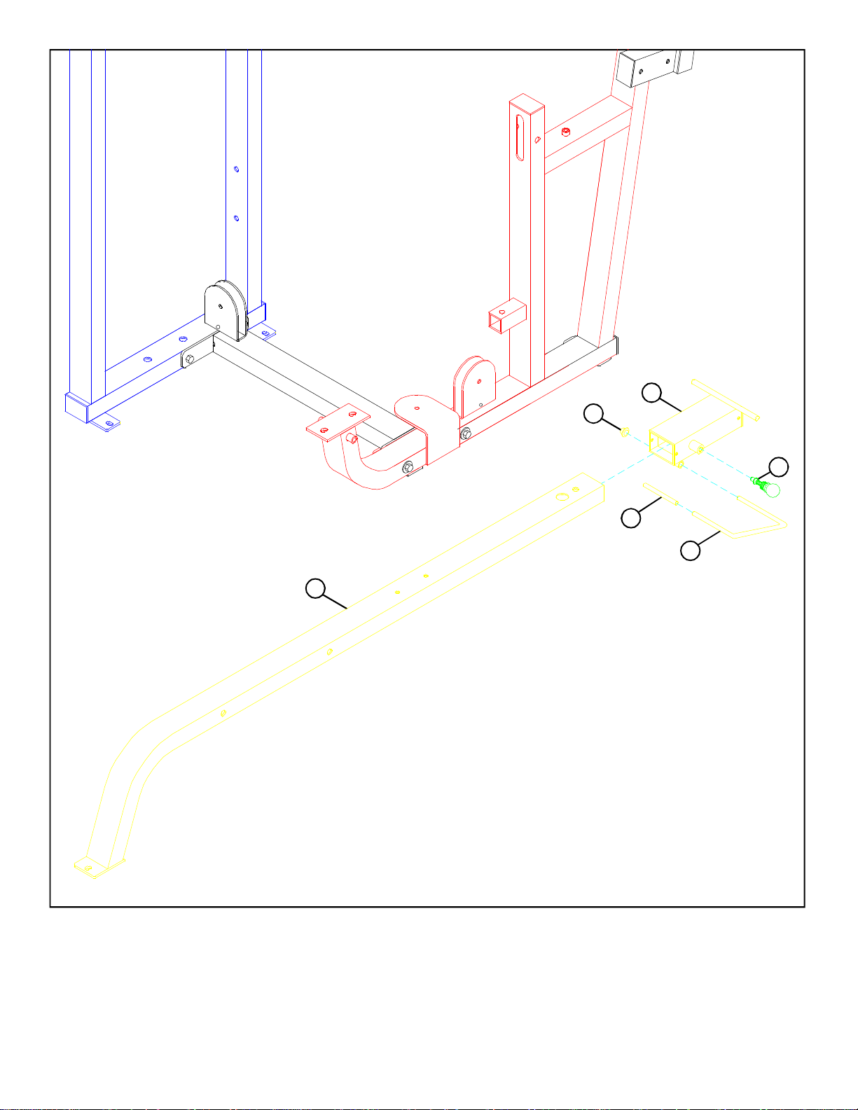
FIGURE 3
STEP 3:
• SECURELY assemble the PRESS FRAME (9) to the PRESS BASE (2) using one 1/2 X 3” BOLT (32), two 1/2” WASHERS (41), and
one 1/2” LOCK NUT (43), as well as two 3/8 X 3” FLAT HEAD BOLTS (36), one 1/4 X 8” PLATE (56), two 3/8” WASHERS (42), and
two 3/8” LOCK NUTS (45) as shown in FIGURE 3. (NOTE: Make sure 3/8” FLAT HEAD BOLTS face downward.)
1/2 1/2 1/2 1/2 1/2 1/2
0
1
2
3 4 5
6
6
Page 7
14
46
3
42
39 3/8 X 1-1/4”
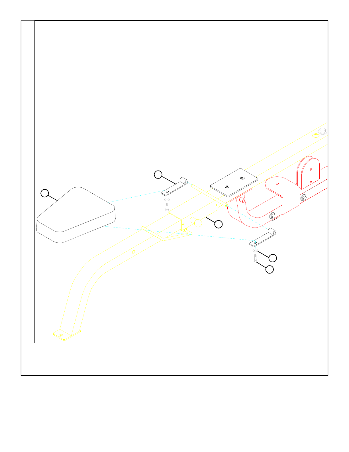
FIGURE 4
STEP 4:
• Slide two HINGE TABS (46) onto the WOLFF SLEEVE (3) and SECUREL Y assemble SEAT PAD (14) using two 3/8 X 1-1/4”
BOLTS (39), and two 3/8” WASHERS (42). See FIGURE 4. (NOTE: Please note the HINGE TAB direction.)
7
Page 8

44
HEIGHT
11
LOW
41
43
12
33 1/2 X 1-1/4”
10
3
1/2 X 6-1/2” 30
FIGURE 5
STEP 5:
• Slide the RIGHT BACK PAD ANGLE (10) and the LEFT BACK PAD ANGLE (11) onto the shaft on the WOLFF SLEEVE (3)
as shown in FIGURE 5.
• Assemble the 1/2 X 2 X 15-1/2” PLATES (12) to the RIGHT BACK PAD ANGLE (10) and the LEFT BACK PAD ANGLE (11)
using two 1/2 X 1-1/4” BOLTS (33), two 1/2” WASHERS (41), and two 1/2” LOW HEIGHT LOCK NUTS (44). (NOTE:
(Tighten nuts securely, then back off 1/4 turn.)
• Assemble the 15-1/2” PLATES (12) to the bushing of the PRESS BASE (2) using one 1/2” X 6-1/2” BOLT (30) and one 1/2” LOCK
NUT (43). (Tighten nut securely, then back off 1/4 turn.) See FIGURE 5.
1/2 1/2 1/2 1/2 1/2 1/2
0
1
2
3 4 5
8
6
Page 9

13
11
42
39 3/8 X 1-1/4”
10
FIGURE 6
STEP 6:
• SECURELY assemble the BACK PAD (13) to the LEFT & RIGHT BACK PAD ANGLES (11 & 10) using four 3/8 X 1-1/4”
BOLTS (39) and four 3/8” WASHERS (42). See FIGURE 6.
9
Page 10

8
51
3/8 X 3-1/4” 35
27
42
SHAFT
45
5
STOP
POST
2
FIGURE 7
STEP 7:
• Slide two PILLOW BLOCKS (27) over the shaft on the PRESS ARM ADJUST (5) and SECURELY assemble the two PILLOW
BLOCKS (27) to the UPPER SUPPORT (8) using four 3/8 X 3-1/4” BOLTS (35), four 3/8” WASHERS (42), and four 3/8” LOCK
NUTS (45) as shown in FIGURE 7.
• Center PRESS ARM ADJUST (5) on top of the STOP POST on the PRESS BASE (2) and securely tighten set screws on the
PILLOW BLOCKS (27). See FIGURE 7.
• Insert two 1/2” FLANGE BEARINGS (51) into the bushings on the PRESS ARM ADJUST (5). See FIGURE 7.
1/2 1/2 1/2 1/2 1/2 1/2
0
1
2
3 4 5
10
6
Page 11

44 1/2” LOW HEIGHT
45
41
4
5
37 3/8 X 2-3/4”
47
29 1/2 X 7-1/2”
FIGURE 8
STEP 8:
• SECURELY assemble one 1/2” SPRING PIN (47) to the PRESS ARM (4) as shown in FIGURE 8. (IMPORTANT! Tighten
spring pin completely.)
• SECURELY assemble the PRESS ARM (4) to the PRESS ARM ADJUST (5) using one 1/2 X 7-1/2” BOLT (29), two 1/2”
WASHERS (41), and one 1/2” LOW HEIGHT LOCK NUT (44). (NOTE: SECURELY tighten, then back nut off 1/4 turn to
allow the press arm to rotate freely.) See FIGURE 8.
• Pull back on 1/2” SPRING PIN (47) to adjust the PRESS ARM (4) position.
• SECURELY assemble four 3/8 X 2-3/4” BOLTS (37) and four 3/8” LOCK NUTS (45) to the PRESS ARM ADJUST (5) as shown in
FIGURE 9.
11
Page 12

16
22
FIGURE 9
STEP 9:
• Snap two WEIGHT PLATE BUSHINGS (22) into the top side of all twenty WEIGHT PLATES (16) as shown in FIGURE 9.
1/2 1/2 1/2 1/2 1/2 1/2
0
1
2
3 4 5
12
6
Page 13

28
20
18
17
16
42
39
3/8 X 1-1/4”
54 155
23
FIGURE 10
STEP 10:
• Insert the two GUIDE RODS (20) into the base of the TOWER (1) as shown in FIGURE 10. Lubricate the GUIDE RODS with a
slicon or teflon spray that is available at most hardware stores.
• Slide two WEIGHT STACK CUSHIONS (23) down over the GUIDE RODS (20). See FIGURE 10.
• Using EXTREME CARE slide twenty WEIGHT PLATES (16) down over the GUIDE RODS (20) with the key-hole facing as
shown in FIGURE 10.
• SECURELY assemble the WEIGHT STACK SHAFT (17) to the HEAD PLATE (18) using one 3/8 X 1-1/4” BOLT (39) and
one 3/8” WASHER (42). (Note: The bolt hole in the HEAD PLATE (18) should be on top.)
• Carefully Slide the HEAD PLATE ASSEMBLY down over the GUIDE RODS (20) onto the weight stack as shown.
• Slide two 13/16” SHAFT COLLARS (28) over the GUIDE RODS (20) as shown in FIGURE 10.
• Apply one set of WEIGHT STACK LABELS - LBS. OR #1-25 (54) (55) to each WEIGHT PLATE (16). See FIGURE 10.
13
Page 14

45
19
7
38 3/8 X 2”
FIGURE 11
STEP 11:
• SECURELY assemble two 4-1/2” PULLEYS (19) to the TOWER BRACE (7) using two 3/8 X 2” BOLTS (38), and two 3/8”
LOCK NUTS (45). See FIGURE 11.
43
41
7
1
31 1/2 X 4”
28
20
FIGURE 12
STEP 12:
• Place TOWER BRACE (7) over the GUIDE RODS (20) and SECURELY assemble TOWER BRACE (7) to the TOWER (1) using
two 1/2 X 4” BOLTS (31), two 1/2” WASHERS (41), and two 1/2” LOCK NUTS (43) as shown in FIGURE 12.
• Slide the 13/16” SHAFT COLLARS (28) to the top of the GUIDE RODS (20) and SECURELY tighten the set screws of the SHAFT
COLLARS (28) set screws. See FIGURE 12.
1/2 1/2 1/2 1/2 1/2 1/2
0
1
2
3 4 5
14
6
Page 15

45
4
5
19
52
45
45
42
19
21
19
37 3/8 X 2-3/4”
53
52
57
34 3/8 X 3-3/4”
2
34 3/8 X 3-3/4”
FIGURE 13
STEP 13:
• SECURELY assemble one of the threaded ends of the CABLE (21) 3/4 of the way into the threaded post on the PRESS BASE
(2) as shown in FIGURE 13.
• Wrap the CABLE (21) around one 4-1/2” PULLEY (19) and SECURELY assemble the pulley to the REAR slot of the PRESS ARM
ADJUST (5) using one 3/8 X 2-3/4” BOLT (37), two 3/8” FLANGE SPACERS (52), and one 3/8” LOCK NUT (45) as shown in FIGURE
13. (NOTE: Loop the cable over the pulley prior to inserting it into the slot.)
• Route CABLE (21) through the slot in the PRESS BASE (2) then SECURELY assemble one 4-1/2” PULLEY (19) to the PRESS BASE (2)
using two 3/8 X 3-3/4” BOLTS (34), two 3/8” FLANGE SPACERS (52), two 2-7/8 X 2-1/4” CABLE CLIPS (2), two 1/2” SPACERS (53), two
3/8” WASHERS (42), and two 3/8” LOCK NUT (45) as shown in FIGURE 13. (NOTE:Make sure the cable is in the groove of the pulley
and over the top of the retaining bolt before tightening it.) (NOTE: Position CABLE CLIPS as shown.)
• Wrap the CABLE (21) around one 4-1/2” PULLEY (19) and SECURELY assemble the pulley to the FRONT slot of the PRESS ARM
ADJUST (5) usinng one 3/8 X 2-3/4” BOLT (37), two 3/8” FLANGE SPACERS (52), and one 3/8” LOCK NUT (45) as shown in FIGURE
13. (NOTE: Loop the cable over the pulley prior to inserting it into the slot.)
15
Page 16

45
9
2
19
21
38 3/8 X 2”
FIGURE 14
STEP 14:
• Route the threaded end of the CABLE (21) through the large hole in the PRESS FRAME (9) as shown in FIGURE 14.
• Wrap the CABLE (21) around one 4-1/2” PULLEY (19) and SECURELY assemble the 4-1/2” PULLEY (19) to the vertical pulley bracket
on the PRESS FRAME (2) using two 3/8 X 2” BOLTS (38) and two 3/8” LOCK NUTS (45) as shown in FIGURE 14. (NOTE: Make sure
CABLE (21) runs over the retaining bolt on the vertical pulley bracket.)
1/2 1/2 1/2 1/2 1/2 1/2
0
1
2
3 4 5
16
6
Page 17

FIGURE 15
19
3/8 X 2” 38
21
2
26
45
STEP 15:
• Wrap the CABLE (21) around one 4-1/2” PULLEY (19) and SECURELY assemble the 4-1/2” PULLEY (19) to the horizontal pulley bracket
on the PRESS FRAME (2) using one 3/8 X 2” BOLT (38), one 2-7/8” CABLE CLIP (26), and one 3/8” LOCK NUT (45) as shown in
FIGURE 15. (NOTE: Before tightening, make sure CABLE CLIP (26) is positioned as shown in FIGURE 15.)
17
Page 18

21
19
38 3/8 X 2”
45
FIGURE 16
6
STEP 16:
• Wrap the CABLE (21) around one 4-1/2” PULLEY (19) and SECURELY assemble the 4-1/2” PULLEY (19) to the vertical pulley bracket
on the LOWER SUPPORT (6) using two 3/8 X 2” BOLTS (38) and two 3/8” LOCK NUTS (45) as shown in FIGURE 16. (NOTE: Make
sure CABLE (21) runs over the retaining bolt on the vertical pulley bracket.)
1/2 1/2 1/2 1/2 1/2 1/2
0
1
2
3 4 5
18
6
Page 19

FIGURE 17
1
7
18
16
STEP 17:
21
17
49
• Route the threaded end of the CABLE (21) through the holes and around the pulleys in the TOWER BRACE (7) as shown in FIGURE
17.
• Screw the treaded end of the CABLE (21) approximately 3/4” into the end of the WEIGHT STACK SHAFT (17) and tighten jam nut
securely. See FIGURE 17.
• If the HEAD PLATE (18) does not sit on top of the first WEIGHT PLATE (16), push the head plate down, insert the SELECTOR PIN
(49) and perform several repetitions on the machine. This will relax the cable system and prevent the HEAD PLATE (18) from lifting
up.
• If after completing the previous step the HEAD PLATE (18) still does not sit on top of the first WEIGHT PLATE (16) or if there is
excess slack in the cable system, adjust the threaded end of the CABLE accordingly and retighten the jam nut.
19
Page 20

15
1
FIGURE 18
STEP 18:
• Slide the SHROUD (15) between the TOWER (1) as shown in FIGURE 18.
1/2 1/2 1/2 1/2 1/2 1/2
0
1
2
3 4 5
20
6
Page 21

3/8 X 1”
BUTTON HEAD
CAP SCREW
40
1
15
FIGURE 19
STEP 19:
• SECURELY assemble the SHROUD (15) to the TOWER (1) using four 3/8 X 1” BUTTON HEAD CAP SCREWS (40) as shown in FIGURE
19.
Thank you for purchasing the LifeFitness 8215 MULTI-PRESS. If unsure of proper use of equipment, call
your local LifeFitness distributor or call the LifeFitness customer service department at (800) 328-9714.
21
 Loading...