

Life Fitness Smart Series, LifeCycle Owner's Manual
SMART SERIES RECUMBENT LIFECYCLE® EXERCISE BIKE
Owner’s Manual
9045501 REV B-2

1
A
MERICAS
North America
Life Fitness Inc.
5100 N River Road
Schiller Park, IL 60176 U.S.A
Telephone: (847) 288 3300
Fax: (847) 288 3703
Service Telephone: (800) 351 3737
Service Email: customersupport@lifefitness.com
Service Website: www.lifefitness.com/parts
Sales/Marketing Email:
consumerproducts@lifefitness.com
Operating Hours: 7:00 am-6:00 pm (CST)
Brazil
Life Fitness Brasil
Av. Cidade Jardim, 900
Jd. Paulistano
São Paulo, SP 01454-000
BRAZIL
SAC: 0800 773 8282
Telephone: +55 (11) 3095 5200
Fax: +55 (11) 3095 5201
Service Email: suporte@lifefitness.com.br
Sales/Marketing Email: lifefitness@lifefitness.com.br
Service Operating Hours:
9:00 - 17:00 (BRT) (Monday-Friday)
Store Operating Hours:
9:00 -20:00 (BRT) (Monday-Friday)
10:00 - 16:00 (BRT) (Saturday)
Latin America & Caribbean*
Life Fitness Inc.
5100 N River Road
Schiller Park, IL 60176 U.S.A
Telephone: (847) 288 3300
Fax: (847) 288 3703
Service Email: customersupport@lifefitness.com
Sales/Marketing Email:commercialsales@lifefitness.com
Operating Hours: 7:00am-6:00pm (CST)
EUROPE, MIDDLE EAST, & AFRICA (EMEA)
Netherlands & Luxemburg
Life Fitness Atlantic BV
Bijdorpplein 25-31
2992 LB Barendrecht
THE NETHERLANDS
Telephone: (+31) 180 646 666
Fax: (+31) 180 646 699
Service Email: service.benelux@lifefitness.com
Sales/Marketing Email:
marketing.benelux@lifefitness.com
Operating Hours: 9.00h-17.00h (CET)
United Kingdom & Ireland
Life Fitness UK LTD
Queen Adelaide
Ely, Cambs, CB7 4UB
Telephone: General Office (+44) 1353.666017
Customer Support (+44) 1353.665507
Fax: (+44) 1353.666018
Service Email: uk.support@lifefitness.com
Sales/Marketing Email: life@lifefitness.com
Operating Hours:
General Office: 9.00am - 5.00pm (GMT)
Customer Support: 8.30am - 5.00pm (GMT)
Germany & Switzerland
Life Fitness Europe GMBH
Siemensstraße 3
85716 Unterschleißheim
GERMANY
Telephone: (+49) 89.31 77 51.0 (Germany)
(+41) 0848 000 901 (Switzerland)
Fax: (+49) 89.31 77 51.99 (Germany)
(+41) 043 818 07 20 (Switzerland)
Service Email: kundendienst@lifefitness.com
Sales/Marketing Email: kundenberatung@lifefitness.com
Operating Hours: 08.30 -16.30h (CET)
Austria
Life Fitness Austria
Vertriebs G.m.b.H.
Dückegasse 7-9/3/36
1220 Vienna
AUSTRIA
Telephone: (+43) 1.61.57.198
Fax: (+43) 1.61.57.198.20
Service Email: kundendienst@lifefitness.com
Marketing/Sales Email: kundenberatung@lifefitness.com
Operating Hours: 08:30-16.30.h (MEZ)
Spain
Life Fitness IBERIA
C/Frederic Mompou 5,1º1ª
08960 Sant Just Desvern Barcelona
SPAIN
Telephone: (+34) 93.672.4660
Fax: (+34) 93.672.4670
Service Email: servicio.tecnico@lifefitness.com
Sales/Marketing Email: info.iberia@lifefitness.com
Operating Hours:
9.00h-18.00h (Monday-Thursday)
8.30h-15.00h (Friday)
Belgium
Life Fitness Benelux NV
Parc Industrial de Petit-Rechain
4800 Verviers
BELGIUM
Telephone: (+32) 87 300 942
Fax: (+32) 87 300 943
Service Email: service.benelux@lifefitness.com
Sales/Marketing Email:
marketing.benelux@lifefitness.com
Operating Hours: 9.00h -17.00h (CET)
Italy
Life Fitness Europe GmbH
Siemensstraße 3
85716 Unterschleißheim
GERMANY
Telephone: (+39) 02-55378611
Service: 800438836 (In Italy)
Fax: (+39) 02-55378699
Service Email: assistenzatecnica@lifefitness.com
Sales/Marketing Email: info@lifefitnessitalia.com
Operating Hours: 08:30 - 16:30h (CET)
All Other EMEA countries &
Distributor Business C-EMEA*
Bijdorpplein 25-31
2992 LB Barendrecht
THE NETHERLANDS
Telephone: (+31) 180 646 644
Fax: (+31) 180 646 699
Service Email: service.db.cemea@lifefitness.com
Sales/Marketing Email:
marketing.db.cemea@lifefitness.com
Operating Hours: 9.00h-17.00h (CET)
ASIA PACIFIC (AP)
Japan
Life Fitness Japan
Nippon Brunswick Bldg., #8F
5-27-7 Sendagaya
Shibuya-Ku, Tokyo
Japan 151-0051
Telephone: (+81) 3.3359.4309
Fax: (+81) 3.3359.4307
Service Email: service@lifefitnessjapan.com
Sales/Marketing Email: sales@lifefitnessjapan.com
Operating Hours: 9.00h-17.00h (JAPAN)
China and Hong Kong
Life Fitness Asia Pacific LTD
Room 2610, Miramar Tower
132 Nathan Road
Tsimshatsui, Kowloon
HONG KONG
Telephone: (+852) 2891.6677
Fax: (+852) 2575.6001
Service Email: HongKongEnquiry@lifefitness.com
Sales/Marketing Email: ChinaEnquiry@lifefitness.com
Operating Hours: 9.00h-18.00h
All Other Asia Pacific countries &
distributor business Asia Pacific*
Room 2610, Miramar Tower
132 Nathan Road
Tsimshatsui, Kowloon
HONG KONG
Telephone: (+852) 2891.6677
Fax: (+852) 2575.6001
Service Email: HongKongEnquiry@lifefitness.com
Sales/Marketing Email: ChinaEnquiry@lifefitness.com
Operating Hours: 9.00h-18.00h
CORPORATE HEADQUARTERS
5100 River Road
Schiller Park, Illinois 60176 • U.S.A.
847.288.3300 • FAX: 847.288.3703
Service phone number: 800.351.3737 (toll-free within U.S.A., Canada)
Global Website: www.lifefitness.com
INTERNATIONAL OFFICES

FCC Warning - Possible Radio / Television Interference
Note: This equipment has been tested and found to comply with the limits for a Class B digital device, pursuant to part
15 of the FCC rules. These limits are designed to provide reasonable protection against harmful interference in a residential installation. This equipment generates, uses and can radiate radio frequency energy, and if not installed and used
in accordance with the user manual, may cause harmful interference to radio communications. However, there is no
guarantee that the interference will not occur in a particular installation. If this equipment does cause harmful interference to radio or television reception, which can be determined by turning the equipment off and on, the user is encouraged to try to correct the interference by one or more of the following measures:
• Reorient or relocate the receiving antenna.
• Increase the separation between the equipment and the receiver.
• Connect the equipment into an outlet on a circuit different from that to which the receiver is connected.
• Consult the dealer or an experienced radio/TV technician for help.
Class HB (Home): Domestic use. Class B is not suitable for therapeutic purposes.
CAUTION: Any changes or modifications to this equipment could void the product warranty.
Any service, other than cleaning or user maintenance, must be performed by an authorized service representative.
There are no user-serviceable parts.
2

TABLE OF CONTENTS
1. Important Safety Instructions . . . . . . . . . . . . . . . . . . . . . . . . . . . . . . . . . . . . . . . . . . . . . . . . . . . . . . . . . . .5
2. Smart Series Recumbent Lifecycle®Exercise Bike Overview . . . . . . . . . . . . . . . . . . . . . . . . . . . . . . . .7
3. Assembly . . . . . . . . . . . . . . . . . . . . . . . . . . . . . . . . . . . . . . . . . . . . . . . . . . . . . . . . . . . . . . . . . . . . . . . . . .8
4. Initial Setup . . . . . . . . . . . . . . . . . . . . . . . . . . . . . . . . . . . . . . . . . . . . . . . . . . . . . . . . . . . . . . . . . . . . . . . .15
5. Main Features . . . . . . . . . . . . . . . . . . . . . . . . . . . . . . . . . . . . . . . . . . . . . . . . . . . . . . . . . . . . . . . . . . . . . .17
6. Smart Console Overview . . . . . . . . . . . . . . . . . . . . . . . . . . . . . . . . . . . . . . . . . . . . . . . . . . . . . . . . . . . . .20
7. How to Use the Smart Console . . . . . . . . . . . . . . . . . . . . . . . . . . . . . . . . . . . . . . . . . . . . . . . . . . . . . . . .22
8. Workouts, Workout Selection Buttons & Settings . . . . . . . . . . . . . . . . . . . . . . . . . . . . . . . . . . . . . . . . . .27
9. Virtual Trainer . . . . . . . . . . . . . . . . . . . . . . . . . . . . . . . . . . . . . . . . . . . . . . . . . . . . . . . . . . . . . . . . . . . . . .33
10. Service and Product Maintenance . . . . . . . . . . . . . . . . . . . . . . . . . . . . . . . . . . . . . . . . . . . . . . . . . . . . .34
11. Specifications . . . . . . . . . . . . . . . . . . . . . . . . . . . . . . . . . . . . . . . . . . . . . . . . . . . . . . . . . . . . . . . . . . . . . .38
12. Warranty Information . . . . . . . . . . . . . . . . . . . . . . . . . . . . . . . . . . . . . . . . . . . . . . . . . . . . . . . . . . . . . . . .39
© 2011 Life Fitness, a division of Brunswick Corporation. All rights reserved.
3

4
This Operation Manual describes the functions of the following product:
Life Fitness Recumbent Lifecycle®Exercise Bike Model:
Smart Series
Thank you for purchasing a Life Fitness bike. Before using this product please read this user manual in its entirety to
ensure that you have the knowledge to safely and properly operate all of the features on your bike. We hope you
achieve the product experience on your bike that you expect, but if you do have any service issues please go to the
How to Obtain Product Service section which will provide information on obtaining domestic and international product
service. See Specifications in this manual for product specific features.
Statement of Purpose: The Life Fitness Lifecycle exercise bike is a machine that simulates the movements of riding a
bicycle at various speeds and levels of resistance.
CAUTION: Health-related injuries may result from incorrect or excessive use of exercise equipment. The
manufacturer STRONGLY recommends seeing a physician for a complete medical exam before undertaking an
exercise program, particularly if the user has a family history of high blood pressure or heart disease; or is over
the age of 45; or smokes, has high cholesterol, is obese, or has not exercised regularly in the past year. The
manufacturer also recommends consulting a fitness professional on the correct use of this product.
If, at any time while exercising, the user experiences faintness, dizziness, pain, or shortness of breath, he or
she must stop immediately.

5
1 IMPORTANT SAFETY INSTRUCTIONS
WARNING: Read all instructions before using the Life Fitness Lifecycle exercise bike. Save these Instructions.
WARNING: Heart rate monitoring systems may be inaccurate. Over exercising may result in serious injury or death.If
you feel faint stop exercising immediately.
WARNING: Any adjustment devices that could interfere with the user’s movement should not be left projecting.
WARNING: Equipment should be installed on a stable base and be properly leveled.
DANGER: To reduce the risk of electrical shock, always unplug this Life Fitness product before cleaning or attempting
any maintenance activity.
SAFETY WARNING: The safety of the product can be maintained only if it is examined regularly for
damage and wear. See Preventive Maintenance section for details.
The heart rate hand pulse sensors provide an approximate heart rate value. The sensors are not medical
devices and should not be used in any type of medical application.
• Before using this product, it is essential to read this ENTIRE operation manual and ALL instructions. The
exercise bike is intended for use solely in the manner described in this manual.
• Always follow the console instructions for proper operation.
• This appliance is not intended for use by persons (including children) with reduced physical, sensory or mental
capabilities, or lack of experience and knowledge, unless they have been given supervision or instruction concerning use of the appliance by a person responsible for their safety.
• Children should be supervised to ensure that they do not play with the appliance.
• Never insert objects into any openings in this product. If an object should drop inside, turn off the power, unplug
the power cord from the outlet and carefully retrieve it. If the item cannot be reached, contact Life Fitness
Customer Support Services.
• Never place liquids of any type directly on the unit, except in an accessory tray. Containers with lids are
recommended.
• Do not use the exercise bike outdoors, near swimming pools or in areas of high humidity.
• Keep all loose clothing, shoelaces, and towels away from the bike pedals.
• Keep the area around the Lifecycle clear of any obstructions, including walls and furniture.
• Use caution when mounting or dismounting the Lifecycle.
• Never operate a Life Fitness product if it has been dropped, damaged, or even partially immersed in water.
Contact Life Fitness Customer Support Services.
• Keep the power cord away from heated surfaces. Do not pull the equipment by the power cord or use the power
cord as a handle.
• Do not run the power cord on the floor under or along side of the Lifecycle.
• Wear shoes with rubber or high-traction soles. Do not use shoes with heels, leather soles, cleats or spikes. Do
not use the Lifecycle in bare feet.
• Do not tip the Lifecycle on its side during operation.
• Keep hands and feet away from all moving parts.
• To ensure proper functioning of this product, do not install attachments or accessories that are not provided or
recommended by Life Fitness.

• Use this product in a well-ventilated area.
• Use this product on a solid, level surface.
• Make sure that all components are fastened securely.
• An appliance should never be left unattended when plugged in. Unplug from outlet when not in use, and before
putting on or taking off parts.
• Do not operate under blanket or pillow. Excessive heating can occur and cause fire, electric shock, or injury to
persons.
• Never operate this appliance if it has a damaged cord or plug, if it is not working properly, if it has been dropped
or damaged, or dropped into water. Contact Life Fitness Customer Support Services.
• Never operate the appliance with the air openings blocked. Keep the air openings free of lint, hair, and the like.
• To disconnect, turn all controls to the off position, then remove plug from outlet.
• Allow LCD consoles to “normalize” with respect to temperature for one hour before plugging the unit in and/or
using.
SAVE THESE INSTRUCTIONS FOR HOUSEHOLD USE.
6

2 SMART SERIES RECUMBENT LIFECYCLE
®
E
XERCISE BIKE OVERVIEW
7
Console
Water Bottle Holder
Contact Heart Rate
Sensors
Pedal

3 ASSEMBLY
3.1 TOOLS & HARDWARE
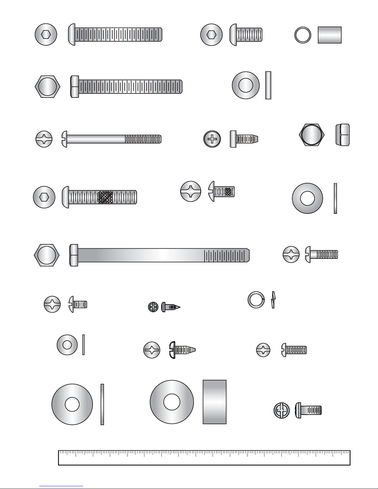
Identify the following components after unpacking your Lifecycle. The tools needed for assembling the product are included.
8
Tools Needed for Assembly:
• Metric Wrench Set
• Metric Allen Wrench Set
• Phillips Screwdriver
Item Quantity Description
1 2 50mm Button Head Screw
2 10 15mm Button Head Screw
3 5 Flat Washer - 18mm O.D.
4 8 55mm Phillips Screw
5 8 Lock Washer - 12.2mm O.D.
6 0 8mm Phillips Screw
7 1 40mm Button Head Screw with Locking Compound
8 1 Flat Washer - 24mm O.D.
9 1 Rubber Bumper Insert
10 1 1” Rubber Bumper
11 2 12mm Phillips Screw with Locking Compound
12 2 12mm Large Head Phillips Screw
13 2 100mm Hex Head Bolt
14 5 Thick Flat Washer - 16mm O.D.
15 2 60mm Hex Head Bolt
16 6 12mm Small Head Phillips Screw
17 4 Flat Washer - 12mm O.D.
18 4 12mm Self-Tapping Screw
19 0 12mm Phillips Screw
20 0 16mm Phillips Screw
21 0 Nylock Nut
22 0 8mm Self-Tapping Screw
10 706020 8030 9040 100 12050 110 130 140 150 160
50mm Button Head Screw
Thick Flat Washer -16mm O.D.
60mm Hex Head Bolt
Flat Washer -12mm O.D.
100mm Hex Head Bolt
8mm Phillips Screw
15mm Button Head Screw
Flat Washer 18mm O.D.
12mm Large Head Phillips Screw
Nylock Nut
1” Rubber Bumper
Flat Washer -24 mm O.D.
Lock Washer - 12.2mm O.D.
40mm Button Head Screw
with Locking Compound
55mm Phillips Screw
12mm Self-Tapping Screw
Rubber Bumper
Sleeve
12mm Phillips Screw with
Locking Compound
8mm Self-Tapping Screw
16mm Phillips Screw
12mm Small Head Phillips Screw
12mm Phillips Screw
9
3.2 PACKAGING
Parts: None
Remove all packaging and place main components to the side of the box. Break box down in each of the four corners.
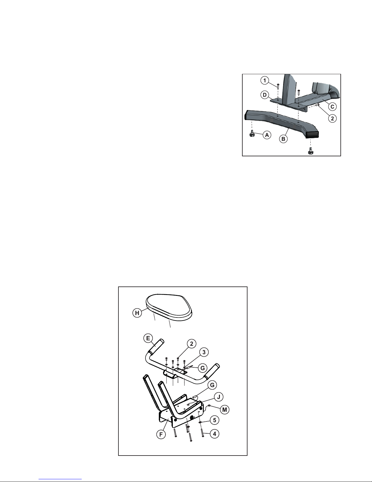
3.3 ASSEMBLE THE REAR STABILIZER
Parts: Hardware Bag #1 (2, 50mm Button Head Screws)
(2, 15mm Button Head Screws)
Tools: 5mm Hex Head Wrench
Locate and install the two LEVELER FEET (A) to the bottom of the REAR STABILIZER (B).With the bends facing rearward, attach the REAR STABILIZER (B) to the
BASE UNIT (C) using two 50mm BUTTON HEAD SCREWS (1) from the top of the
REAR STABILIZER BRACKET (D) and two 15mm BUTTON HEAD SCREWS (2)
from the front side of the REAR STABILIZER BRACKET. Tighten the SCREWS
securely.
3.4 SECURE HANDLEBAR ASSEMBLY TO SEAT ASSEMBLY
Parts: Hardware Bag #2 (4, 15mm Hex Head Bolts)
(4, 55mm Phillips Screws)
(4, Lock Washers)
(4, 18mm O.D. Flat Washers)
Tools: 5mm Hex Head Wrench, Phillips Screwdriver
Locate the HANDLEBAR ASSEMBLY (E) and the SEAT ASSEMBLY (F). With the handlebars facing upward and forward, align the mounting holes of the HANDLEBAR ASSEMBLY with those in the SEAT ASSEMBLY. Secure the HANDLEBAR ASSEMBLY to the SEAT ASSEMBLY using four 15mm BUTTON HEAD SCREWS (2) and FLAT WASHERS
(3). Tighten the SCREWS securely. Connect the CONNECTOR (G) leading from the HANDLEBAR ASSEMBLY (E) with
the CONNECTOR (G) leading from the SEAT ASSEMBLY (F). Be sure the connectors fully lock.
Locate the SEAT BOTTOM (H). Align the SEAT BOTTOM mounting holes with those in the LOWER SEAT SUPPORTS
(J). Secure the SEAT BOTTOM using four 55mm PHILLIPS SCREWS (4) and LOCK WASHERS (5). Tighten the
SCREWS securely.
10
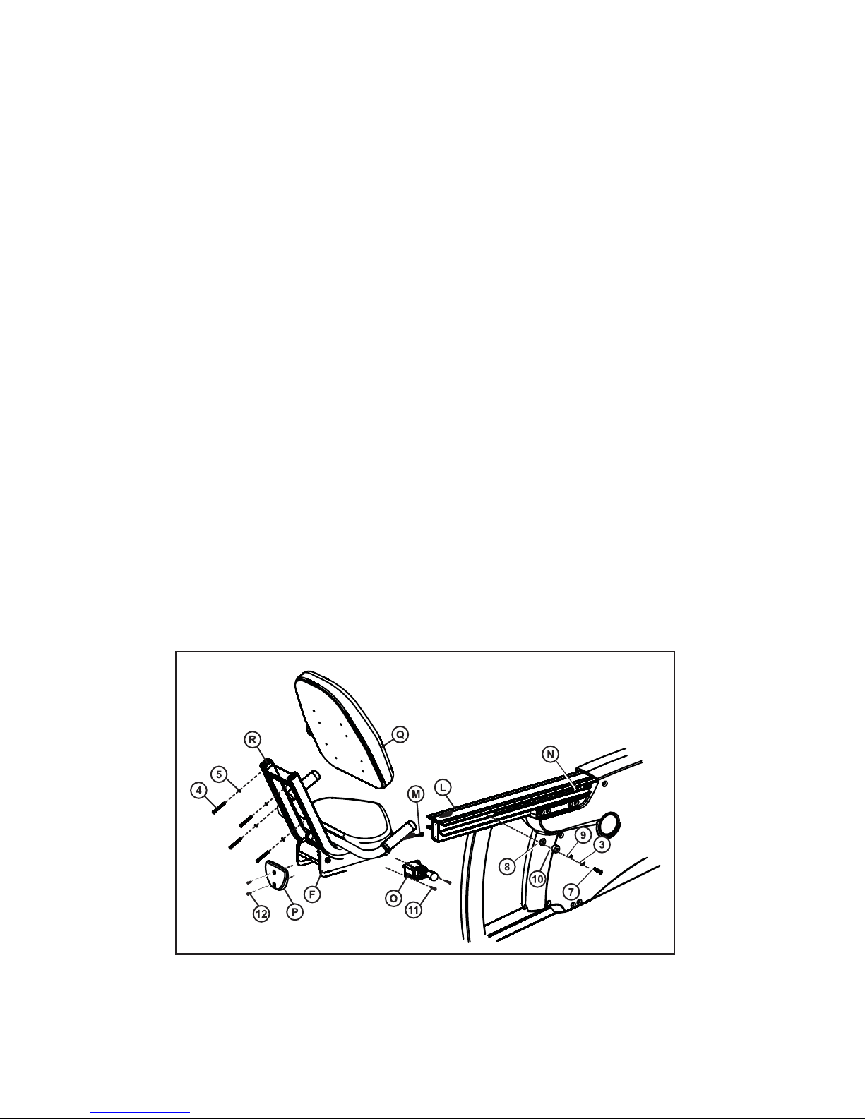
3.5 SEAT ADJUSTMENT AND SEAT BACK PAD
Parts: Hardware Bag #3 (1, 40mm Button Head Screw with Locking Compound)
(1, 24mm Flat Washer)
(1, Rubber Bumper Sleeve)
(1, Rubber Bumper 1”)
(1, 18mm Flat Washer)
(2, 12mm Phillips Screws with Locking Compound)
(2, 12mm Phillips Screws)
(4, 55mm Phillips Screws)
Tools: 5mm Hex Head Wrench, Phillips Screwdriver, 13mm Socket Wrench
Align the guide rollers located on the underside of the SEAT ASSEMBLY (F) with the SEAT EXTRUSION (L). Carefully
guide the SEAT ASSEMBLY onto the SEAT EXTRUSION. Slide the SEAT ASSEMBLY fully forward. Connect the WIRE
(M) leading from the user left side of the SEAT ASSEMBLY to the JACK located at the left front of the SEAT EXTRUSION. Insert the WIRE (M) into the WIRE HARNESS (N) located next to the JACK.
Note: The WIRE (M), JACK and WIRE HARNESS (N) are located on the user left side of the unit. Items shown on the
right for clarity.
In the hole located on the user right side of the SEAT EXTRUSION (L), behind the SEAT ASSEMBLY (F), install one
40mm BUTTON HEAD SCREW WITH LOCKING COMPOUND (7), one 24mm FLAT WASHER (8), one RUBBER
BUMPER SLEEVE (9), one 1" RUBBER BUMPER (10) and one 18mm FLAT WASHER (3) as shown.
Mount the SEAT ADJUSTMENT LEVER (O) to the user right side of the SEAT ASSEMBLY (F) using two 12 mm
PHILLIPS SCREWS W/LOCKING COMPOUND (11). Tighten the SCREWS securely.
Note: Be sure to mount the SEAT ADJUSTMENT LEVER (O) with the adjustment knob facing upward as shown.
Locate the SEAT EXTRUSION ENDCAP (P). Secure the SEAT EXTRUSION ENDCAP to the SEAT EXTRUSION (L)
using two 12mm PHILLIPS SCREWS (12).
Secure the SEAT BACK PAD (Q) to the UPPER SEAT SUPPORT TUBES (R) using four 55mm PHILLIPS SCREWS (4)
and LOCK WASHERS (5). Tighten the SCREWS securely.
11
12
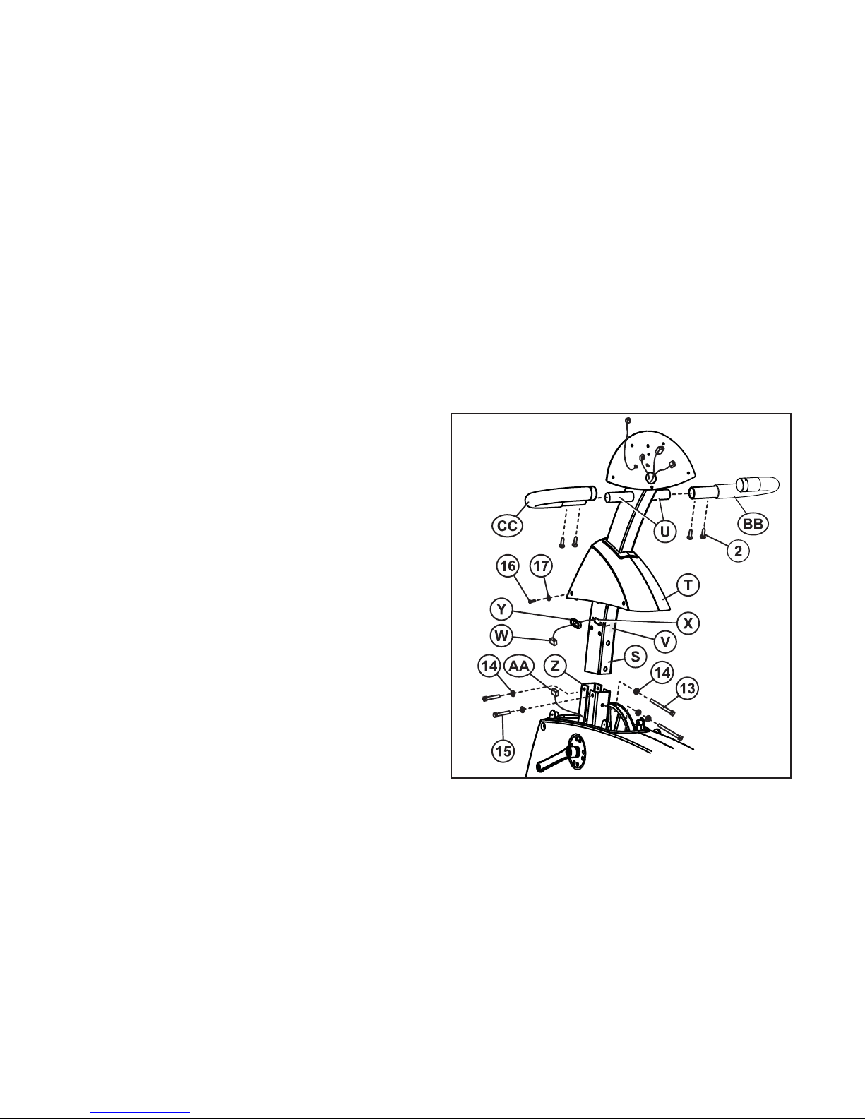
3.6 MONOCOLUMN, WIRING AND COVER
Parts: Hardware Bag #4 (2, 100mm Hex Head Bolts)
(5, Thick Flat Washers - 16mm O.D.)
(2, 60mm Hex Head Bolts)
(4, 12mm Phillips Screws)
(4, Flat Washers - 12mm O.D.)
(4, 15mm Button Head Screws)
Tools: 13mm Socket Wrench, 5mm Hex Head Wrench, Phillips Screwdriver
Locate the MONOCOLUMN (S). Slide the MONOCOLUMN COVER (T) onto the MONOCOLUMN as shown. Slide the
MONOCOLUMN COVER up to the FRONT HANDLEBAR POSTS (U).
Note: A zip-tie has been included to keep the MONOCOLUMN COVER (T) from falling during assembly.
Detach the WIRE TIE (V) attached to the front of the MONOCOLUMN (S). Carefully pull the CONSOLE WIRE (W)
through the SIDE ACCESS HOLE (X) of the MONOCOLUMN. Feed the CONSOLE WIRE through the GROMMET (Y)
as shown and insert the GROMMET into the SIDE ACCESS HOLE. Slide the MONOCOLUMN (S) into the MONOCOLUMN BRACKET (Z). Slide the MONOCOLUMN down until it is fully seated. Secure the MONOCOLUMN to the MONOCOLUMN BRACKET using two 100mm HEX HEAD BOLTS (13) and three THICK FLAT WASHERS (14) from the front
side of the MONOCOLUMN and two 60mm HEX HEAD BOLTS (15) and THICK FLAT WASHERS (14) from the user left
side of the MONOCOLUMN BRACKET. Tighten the BOLTS securely.
Note: The two 100mm HEX HEAD BOLTS (13) and three THICK
FLAT WASHERS (14) are shown entering from the back side of
the MONOCOLUMN for clarity. Please secure from the FRONT
side.
CAUTION: Be careful not to pinch the WIRE(s) (AA) leading from
the MONOCOLUMN BRACKET (Z) when inserting the MONOCOLUMN (S) into the MONOCOLUMN BRACKET.
Connect the WIRE(s) (AA) leading from the MONOCOLUMN
BRACKET (Z) to the corresponding WIRE (W) from the SIDE
ACCESS HOLE (X) of the MONOCOLUMN. Slide the MONOCOLUMN COVER (T) downward to meet the MAIN SHROUDS.
Secure the MONOCOLUMN COVER to the MAIN SHROUDS
using four 12mm PHILLIPS SCREWS (16) and four 12mm O.D.
WASHERS (17). Tighten the SCREWS securely. Do not overtighten the SCREWS.
Attach the RIGHT (BB) and LEFT (CC) FRONT HANDLEBARS
(labeled right and left) to the MONOCOLUMN as shown using
two each 15mm BUTTON HEAD SCREWS (2). Tighten the
SCREWS securely
 Loading...