

Life Fitness LC8500R, LC9100R, 90R, 95Re, R9 Service Manual
...
Lifecycle Recumbent Bikes
LC9500R, LC9100R, LC8500R,
R9, R7, 95Ri, 93Ri, 90R, and 95Re
Customer Support Services
SERVICE MANUAL

Lifecycle Recumbent Bikes LC95R, LC91R, LC85R, R9, R7, 95Ri, 93Ri, 90R, and 95Re
GENERAL CONTENTS
INTRODUCTION ...............................................................................................................ii
SPECIAL SERVICE TOOLS .............................................................................................iii
GLOSSARY (Pending) .....................................................................................................iv
COMPONENT IDENTIFICATION......................................................................................v
SECTIONAL CONTENTS
TROUBLESHOOTING 1
DIAGNOSTICS LED 2A
DIAGNOSTICS LCD 2B
HOW TO…SERVICE 3
ELECTRONICS 4
MISCELLANEOUS 5
i

Lifecycle Recumbent Bikes LC95R, LC91R, LC85R, R9, R7, 95Ri, 93Ri, 90R, and 95Re
INTRODUCTION
This service manual is applicable to Recumbent Exercise Bikes LC9500R, LC9100R, LC8500R, R9, R7, 95Ri,
93Ri, 90R, and 95Re Information represents typical configuration and may differ slightly from actual equipment.
The service manual provides recommendations for safe and efficient approaches to problem situations.
If an operating problem should arise, turn to the TROUBLESHOOTING GUIDES and attempt to isolate what is
causing the malfunction. The GUIDES are listed by symptoms and follow with suggestions as to the most probable
cause of the problem.
Once you have pinpointed the source of the problem, turn to the appropriate "How To..." section and review the
proper procedures for removing, replacing or adjusting a part. The "How To..." sections are organized by
replaceable part (or assembly) name and each page lists the “Special Tools Required“to complete the specific task.
Refer to COMPONENT IDENTIFICATION in the front part of this section to locate and identify in order service
repair parts for your machine.
If you do not have a part in stock, a form to order by FAX has been included in Section V for your convenience or
you can call Life Fitness Customer Support Services any Monday through Friday from 8:00 AM to 6:00 PM
(C.S.T.). When you place a call, in order to speed our response to your particular situation, please have the
following information available for the customer service phone technician who will be prepared to assist you:
1. The Lifecycle equipment model number
2. The serial number
3. The symptom of the problem
4. The part name and number to order
When you receive your order, review the appropriate "How To..." section and follow the step by step procedures
designed to help you install the part quickly and correctly.
If you have any questions or comments please phone, mail, or fax us at:
LIFE FITNESS COMPANY - CUSTOMER SUPPORT SERVICES
10601 Belmont Avenue, Franklin Park, IL 60131; U.S.A.
Telephone: 847-451-0036, Toll Free: 800-351-3737, FAX: 847-288-3702
ii

Lifecycle Recumbent Bikes LC95R, LC91R, LC85R, R9, R7, 95Ri, 93Ri, 90R, and 95Re
SPECIAL SERVICE TOOL REQUIREMENTS
Unless otherwise specified, only basic hand tools are required to perform service procedures
outlined in this section. Some of these standard tools should consist of: Philips and StraightBlade Screw Drivers, Torx Set, Pliers, Rubber Mallet, Pry Bar, Snap Ring Pliers (internal and
external), Standard and Metric size Socket Set (3/8 or 1/2 drive), and Standard and Metric size
Combination, open-end, or Box Wrenches.
Specialized tools will be listed after the sub-heading Special Service Tools:, which appears
below the Service Procedure heading at the top of the page. If no specialized tools are
required, then the title would read: Special Service Tools: NONE, which means that standard
hand tools should be employed to provide service to the product.
Specialized tools must be used to safely and effectively complete the service procedures.
Improvisation or attempts to use any other tool could result in unnecessary damage to the
equipment or personal injury.
iii

Lifecycle Recumbent Bikes LC95R, LC91R, LC85R, R9, R7, 95Ri, 93Ri, 90R, and 95Re
GLOSSARY
PENDING
iv

Lifecycle Recumbent Bikes LC95R, LC91R, LC85R, R9, R7, 95Ri, 93Ri, 90R, and 95Re
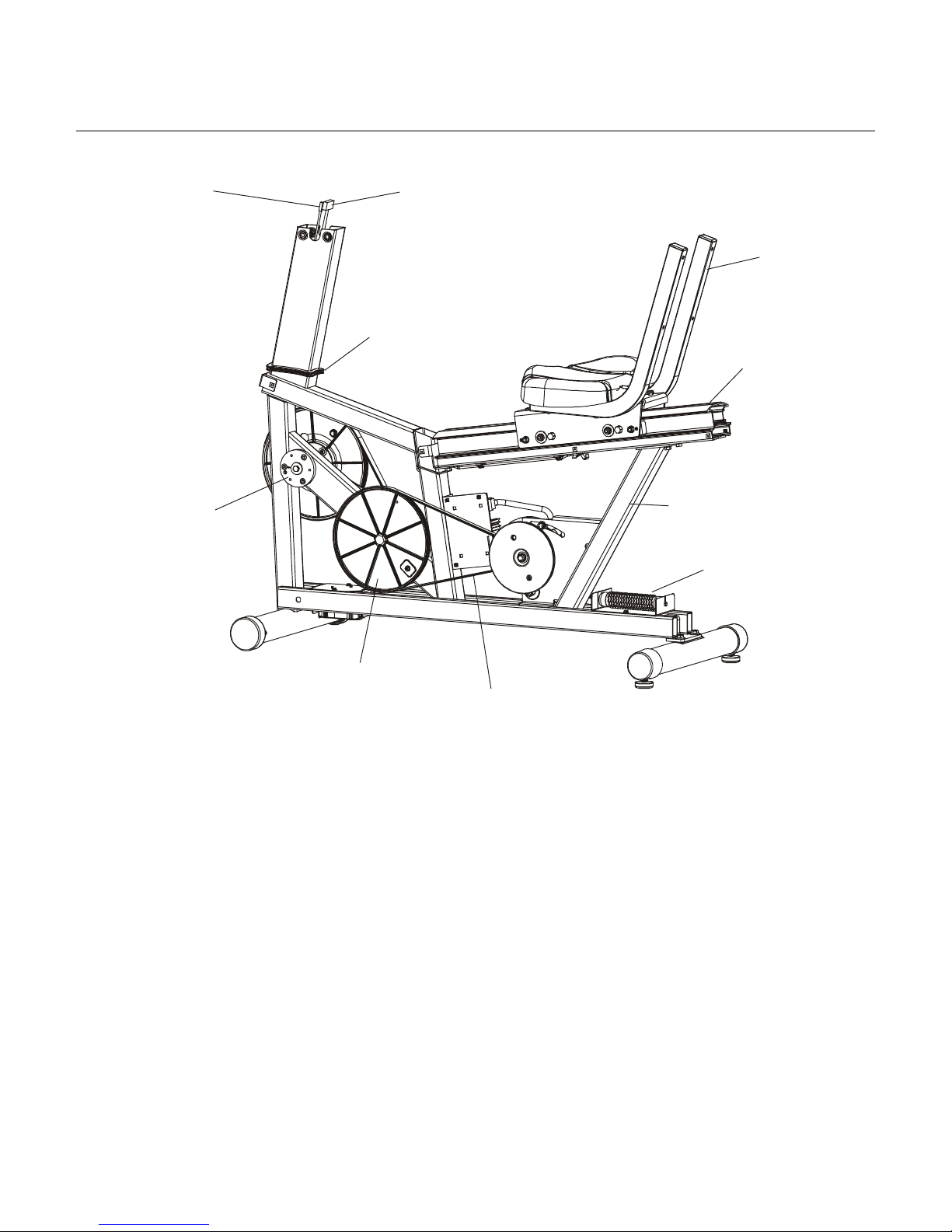
COMPONENT IDENTIFICATION
Console
Console
Support
Assembly
Seat Back
Handlebar
End Cap
Left Side
Shroud
Left Pedal
Seat Pad
Right
Crank Arm
Right
Pedal
Wheel
Accessory
Tray
Rear Stabilizer
Right Side
Shroud
Leveler
v
Lifecycle Recumbent Bikes LC95R, LC91R, LC85R, R9, R7, 95Ri, 93Ri, 90R, and 95Re
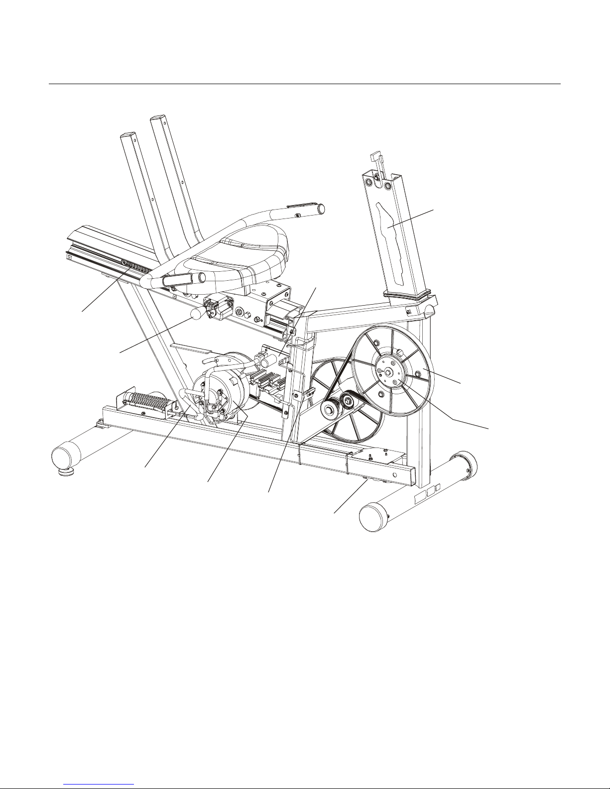
COMPONENT IDENTIFICATION
Heart
Rate
Cable
Left
Crank Arm
Hub
Main Cable
Seat
Assembly
Shroud
Gasket
Extrusion
Frame
Resistor
Assembly
Intermediate
Pulley
Alternator
Belt
vi
Lifecycle Recumbent Bikes LC95R, LC91R, LC85R, R9, R7, 95Ri, 93Ri, 90R, and 95Re
COMPONENT IDENTIFICATION
Decal
Power
Control
Board
Rack
Locking
Mechanism
Alternator
Cable
Alternator
Reed
Switch
Crank Arm
Pulley
Right
Crank Arm
Hub
Battery
vii

Lifecycle Recumbent Bikes LC95R, LC91R, LC85R, R9, R7, 95Ri, 93Ri, 90R, and 95Re
NOTES:
viii

Lifecycle Recumbent Bikes LC95R, LC91R, LC85R, R9, R7, 95Ri, 93Ri, 90R, and 95Re
SECTION I
TROUBLESHOOTING
GUIDES
Page
Display Console LEDs Not Illuminating............................................................................... 3
Display Console Initializes Then Fails................................................................................. 3
No Prompt ...........................................................................................................................3
LEDs Not Constant..............................................................................................................4
LEDs Do Not Extinguish...................................................................................................... 4
Prompt Flashes ...................................................................................................................4
Display Console Keys Do Not Function ..............................................................................4
Excessive Resistance is Immediate.................................................................................... 5
Excessive Resistance Loading Occurs ...............................................................................5
Resistance Varies During Manual Mode............................................................................. 5
RANDOM and HILL Resistance is Constant, No Variation .................................................6
Pedaling Is Difficult.............................................................................................................. 6
Pedaling is to Easy.............................................................................................................. 6
Inadequate Resistance During Pedaling............................................................................. 7
Battery Over-Heating...........................................................................................................7
Bike Not Stable ...................................................................................................................7
Loud Noise ..........................................................................................................................7
No Heart Rate .....................................................................................................................8
Channels Do Not Change ...................................................................................................8
Sound Does Not Change ....................................................................................................8
Faulty PCB ..........................................................................................................................8
No Sound ............................................................................................................................8
Unable to Receive Channels............................................................................................... 9
Snow and Noise ..................................................................................................................9
Screen is Blank ...................................................................................................................9
Screen Does Not Respond To Touch .................................................................................9
Wrong Buttons Activated when Touching Screen............................................................... 9
No Buttons Activated when Touching Screen..................................................................... 9
Screen Does Not Turn ON and No Audio ...........................................................................9
Testing the Inverter Board................................................................................................... 10
Testing the Power Supply Cable......................................................................................... 11
Notes...................................................................................................................................12
1

Lifecycle Recumbent Bikes LC95R, LC91R, LC85R, R9, R7, 95Ri, 93Ri, 90R, and 95Re
TROUBLESHOOTING GUIDE
Notes
2
Lifecycle Recumbent Bikes LC95R, LC91R, LC85R, R9, R7, 95Ri, 93Ri, 90R, and 95Re
TROUBLESHOOTING GUIDE
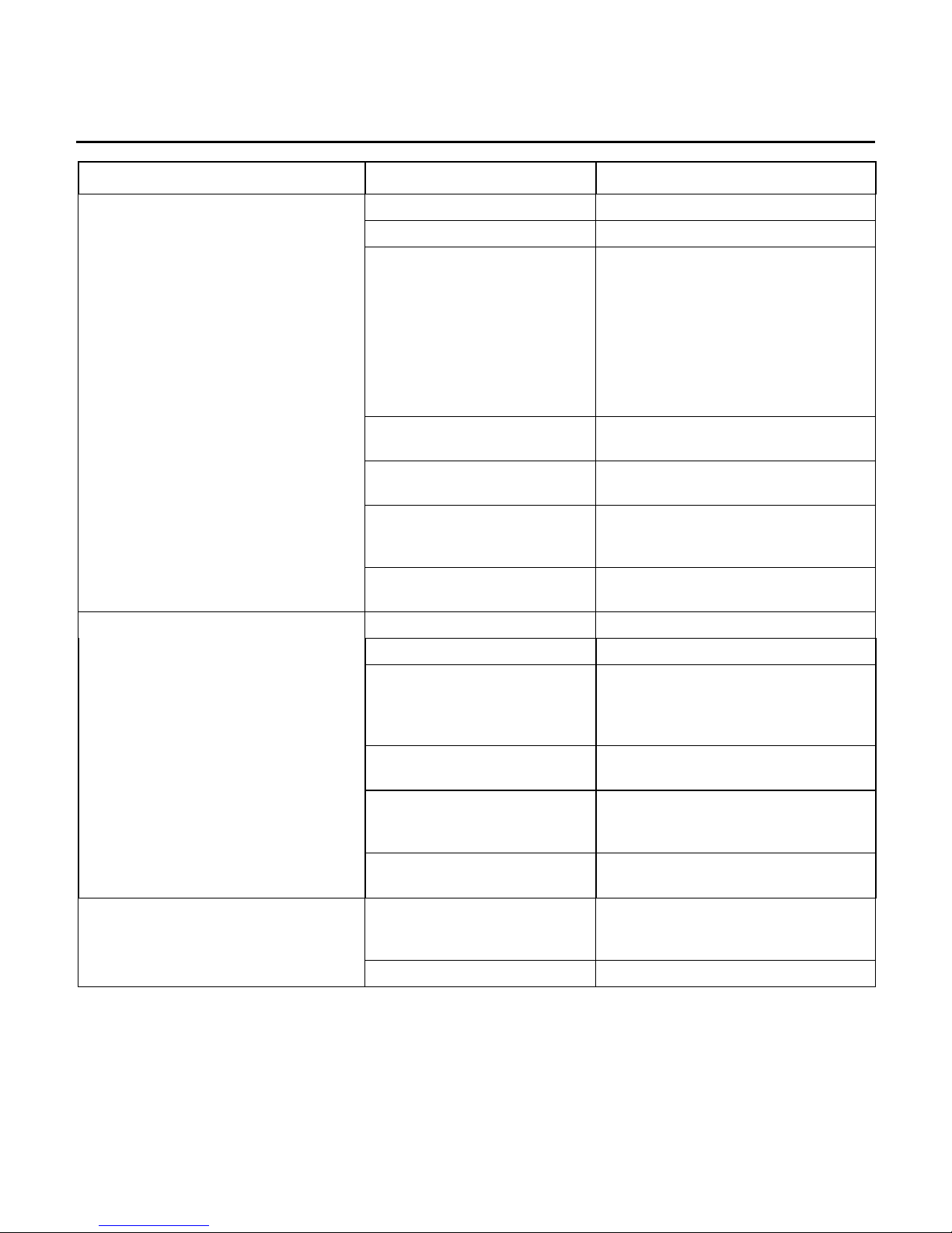
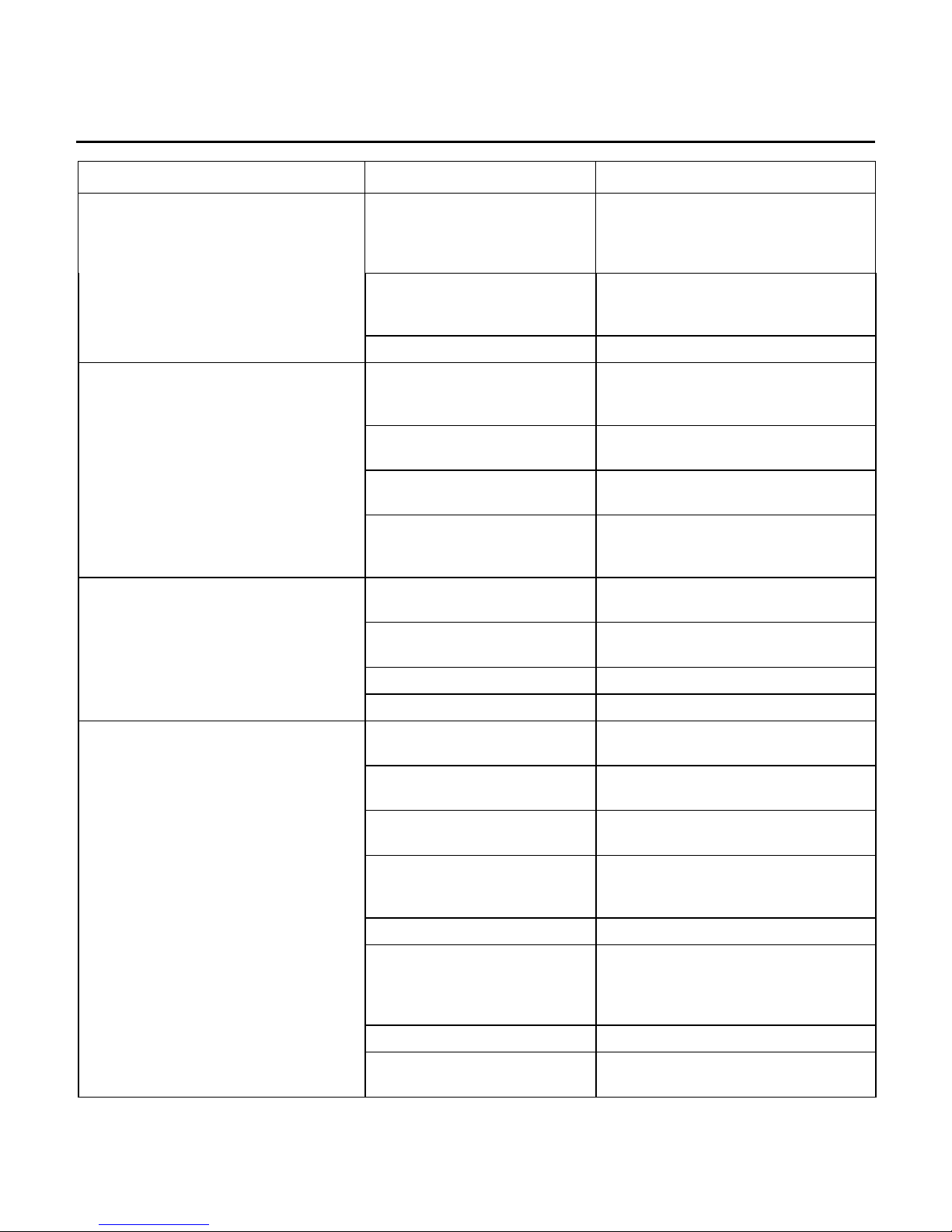
SYMPTOM PROBABLE CAUSE CORRECTIVE ACTION
Display Console LEDs not illuminating
Display console initializes then fails
Auto start not responding. Check auto start not responding.
Keypad not responding. Test keypad in diagnostics.
Insufficient battery voltage. Check battery voltage. The LC9500,
LC9100, and C9i have a 6VDC
battery (non-alkaline) which should
test at a minimum of 6.0 VDC. The
LC8500, and C7 has a 9VDC alkaline
battery and it should test at a
minimum of 9.0 VDC. Replace battery
if it fails to meet minimum
requirements.
Loose wire connections. Disconnect then reconnect
connections.
Worn or damaged wire
harnesses.
Malfunctioning display
console.
Malfunctioning alternator
control board (ACB).
Loose wire connections. Disconnect then secure connections.
No RPM. Enter Diagnostic and check for RPM.
Inspect wire harnesses. Replace
worn or damaged harness.
Test with substitute display console.
Replace malfunctioning display
console.
Test with substitute ACB. Replace
malfunctioning ACB.
No prompt upon release of START
key. Entry of additional information not
allowed.
Malfunctioning alternator. Test alternator output or test with
substitute alternator. Replace
malfunctioning alternator. Refer to
Alternator Voltage Test.
Malfunctioning alternator
control board.
Malfunctioning display
console.
Worn or damaged wire
harnesses.
Malfunctioning display
console.
Battery drained. Replace Battery with new one.
Test with substitute alternator control
board. Replace malfunctioning board.
Test with substitute display console.
Replace malfunctioning display
console.
Inspect wire harnesses. Replace
worn or damaged harness.
Test with substitute display console.
Replace malfunctioning display
console.
3
Lifecycle Recumbent Bikes LC95R, LC91R, LC85R, R9, R7, 95Ri, 93Ri, 90R, and 95Re
TROUBLESHOOTING GUIDE
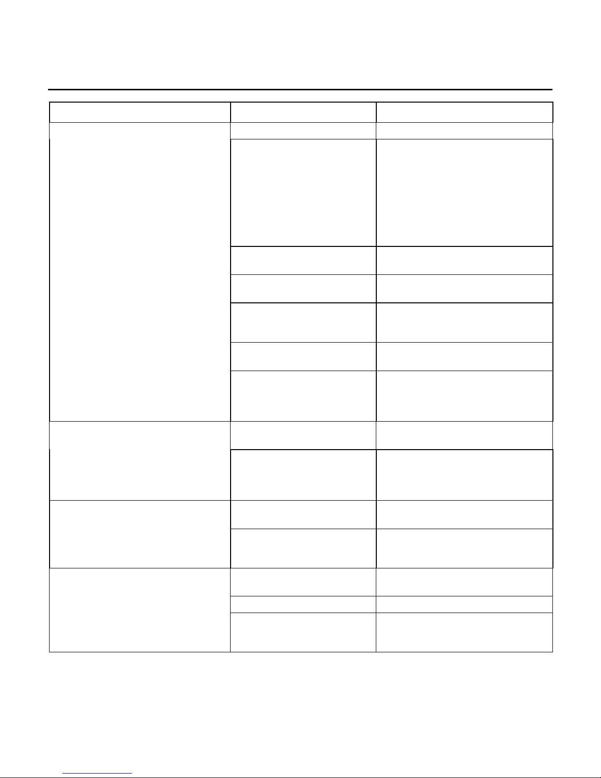
SYMPTOM PROBABLE CAUSE CORRECTIVE ACTION
Display Console LEDs are not
constant
Pedaling to slowly Pedal faster than 35 RPM.
Insufficient battery voltage Check battery voltage. The LC9500,
LC9100, and C9i have a 6VDC
battery (non-alkaline) which should
test at a minimum of 6.0 VDC. The
LC8500, and C7 has a 9VDC alkaline
battery and it should test at a
minimum of 9.0 VDC. Replace battery
if it fails to meet minimum
requirements.
Loose wire connections Disconnect then reconnect
connections.
Display Console LEDs do not
extinguish in timely manner at the end
of a workout, when the CLEAR key is
pressed, or when the pedaling stops.
Prompt persistently flashes and entry
of additional information is not allowed.
Display Console keys (except START
key) do not function and Exercise Bike
does not respond.
Worn or damaged wire
harnesses
Malfunctioning Display
Console
Malfunctioning Alternator
Control Board
Malfunctioning Alternator Test Alternator output or test with
Malfunctioning Alternator
Control Board
Malfunctioning Display
Console
Attempting to enter improper
duration of time
Malfunctioning Display
Console
Attempting to enter program
not available.
Malfunctioning Keypad Test Keypad in Diagnostics.
Malfunctioning Display
Console
Inspect wire harnesses. Replace
worn or damaged harnesses.
Test with substitute Display Console.
Replace malfunctioning Display
Console.
Test with substitute Alternator Control
Board. Replace malfunctioning board.
substitute Alternator. Replace
malfunctioning Alternator. Refer to
Alternator Voltage Test.
Test with substitute Alternator Control
Board. Replace defective board.
Inspect for damage or depression at
START key. Test with substitute
Display Console. Replace
malfunctioning Display Console.
Refer to Operation Manual for time
duration requirements.
Test with substitute Display Console.
Replace malfunctioning Display
Console.
Refer to Operation Manual for
program availability.
Test with substitute Display Console.
Replace malfunctioning Display
Console.
4
Lifecycle Recumbent Bikes LC95R, LC91R, LC85R, R9, R7, 95Ri, 93Ri, 90R, and 95Re
TROUBLESHOOTING GUIDE
SYMPTOM PROBABLE CAUSE CORRECTIVE ACTION
Upon start of program, excessive
resistance load is immediate; no
normal, incremental increase from “no
load.”
Insufficient battery voltage Check battery voltage. The LC9500,
LC9100, and C9i have a 6VDC
battery (non-alkaline) which should
test at a minimum of 6.0 VDC. The
LC8500, and C7 has a 9VDC alkaline
battery and it should test at a
minimum of 9.0 VDC. Replace battery
if it fails to meet minimum
requirements.
Loose wire connections Disconnect then, reconnect
connections.
During program, excessive resistance
loading occurs.
During MANUAL program, resistance
variation occurs.
Worn or damaged wire
harnesses
Malfunctioning Display
Console
Malfunctioning Alternator
Control Board
Malfunctioning Alternator Test Alternator output or, test with
Loose wire connections Disconnect then, reconnect
Worn or damaged wire
harnesses
Malfunctioning Display
Console
Malfunctioning Alternator
Control Board (ACB)
Malfunctioning Alternator Test Alternator output or, test with
Pedaling too slowly Pedal faster than 35 RPM.
Loose wire connections Disconnect then, reconnect
Worn or damaged harnesses Inspect wire harnesses. Replace
Malfunctioning Display
Console
Inspect wire harnesses. Replace
worn or damaged harness.
Test with substitute Display Console.
Replace malfunctioning Display
Console.
Test with substitute Alternator Control
Board. Replace malfunctioning board.
substitute Alternator. Replace
malfunctioning Alternator. Refer to
Alternator Voltage Test.
connections.
Inspect wire harnesses. Replace
worn or damaged harness.
Test with substitute Display Console.
Replace Display Console.
Test with substitute ACB. Replace
malfunctioning ACB.
substitute Alternator. Replace
malfunctioning Alternator. Refer to
Alternator Voltage Test.
connections.
worn or damaged harness.
Test with substitute Display Console.
Replace Display Console.
5
Lifecycle Recumbent Bikes LC95R, LC91R, LC85R, R9, R7, 95Ri, 93Ri, 90R, and 95Re
TROUBLESHOOTING GUIDE
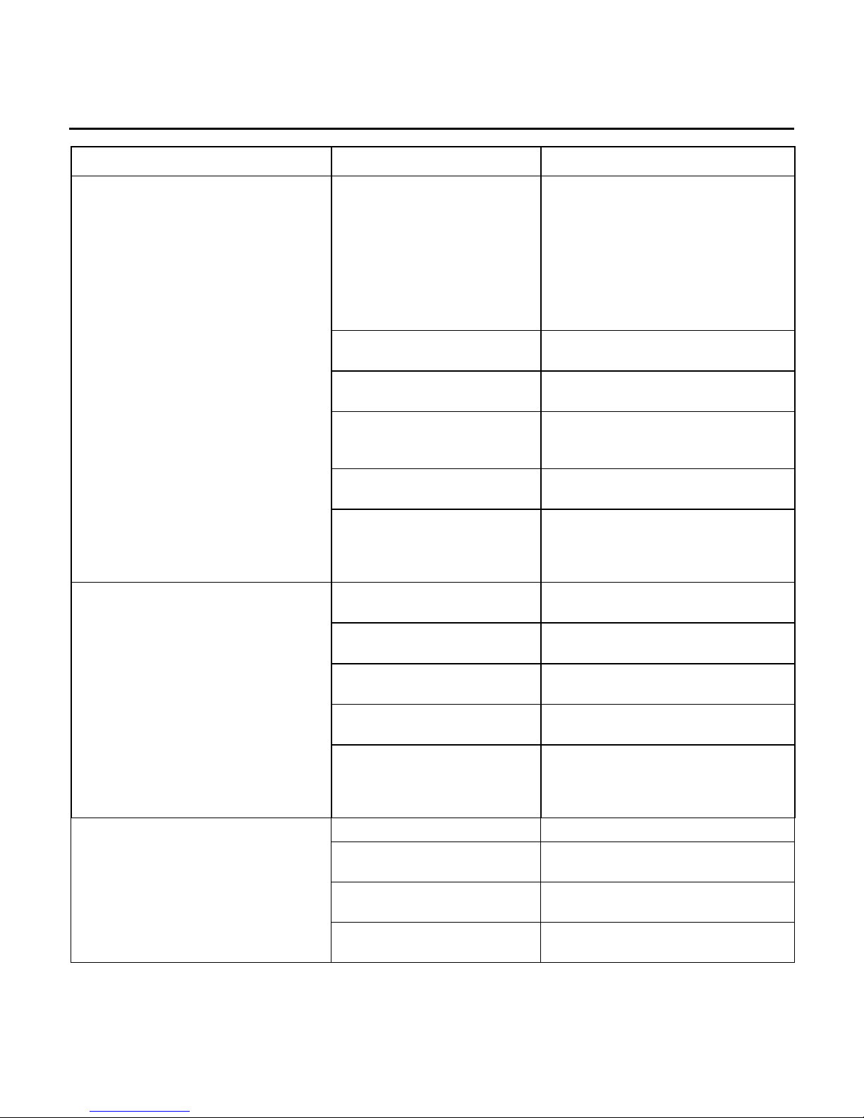
SYMPTOM PROBABLE CAUSE CORRECTIVE ACTION
During MANUAL program, resistance
variation occurs.
During RANDOM or HILL programs,
resistance is constant without variation
for interval training nor hill
incline/decline.
Malfunctioning Alternator
Control Board
Malfunctioning Alternator Test Alternator output or, test with
Loose wire connections Disconnect then, reconnect
Worn or damaged harnesses Inspect wire harnesses. Replace
Test with substitute Alternator Control
Board. Replace defective board.
substitute Alternator. Replace
malfunctioning Alternator. Refer to
Alternator Voltage Test.
connections.
worn or damaged harness.
Pedaling is difficult, feels restricted or,
is not possible when Exercise Bike has
not been started (START key not
pressed).
During exercise program, pedaling is
insufficiently easy, not providing
adequate resistance.
Malfunctioning Display
Console
Malfunctioning Alternator
Control Board
Malfunctioning Alternator Test Alternator output or, test with
Malfunctioning Pulley Clutch
Assembly
Alternator Belt excessively
tight
Alternator Belt Alignment is
OFF
Crank bearings worn or
corroded
Pedaling too slowly Pedal faster than 30 RPM.
Program level doesn’t
challenge user ability
Loose wire connections Disconnect then, reconnect
Worn or damaged harnesses Inspect wire harnesses. Replace
Malfunctioning Display
Console
Malfunctioning Alternator
Control Board
Test with substitute Display Console.
Replace malfunctioning Display
Console.
Test with substitute Alternator Control
Board. Replace defective board.
substitute Alternator. Replace
malfunctioning Alternator. Refer to
Alternator Voltage Test.
Inspect Clutch for free backward and
forward rotation. Replace
malfunctioning Pulley Clutch or
Freewheel.
Inspect belt deflection. Adjust as
necessary.
Alternator Belt Deflection: 1/4 inch
(6mm)
Realign alternator belt to far users left
groove of the alternator pulley, not in
the center.
Replace Crank Bearings.
Select higher level.
connections.
worn or damaged harness.
Test with substitute Display Console.
Replace malfunctioning Console.
Test with substitute Alternator Control
Board. Replace defective board.
6
Lifecycle Recumbent Bikes LC95R, LC91R, LC85R, R9, R7, 95Ri, 93Ri, 90R, and 95Re
TROUBLESHOOTING GUIDE
SYMPTOM PROBABLE CAUSE CORRECTIVE ACTION
During exercise program, pedaling is
insufficiently easy, not providing
adequate resistance.
Malfunctioning Alternator Test Alternator output or, test with
substitute Alternator. Replace
malfunctioning Alternator. Refer to
Alternator Voltage Test.
Alternator Belt excessively
loose
Drive Belt excessively loose Inspect Belt. Replace Belt.
Inspect belt deflection. Adjust as
necessary. Alternator Belt Deflection:
1/4 inch (6mm)
Battery over-heating during exercise
program.
Exercise Bike not stable upon floor.
During exercise program, loud noise
issuing from Exercise Bike.
Battery Wires incorrectly
connected
Worn Battery Wires Inspect Wires. Replace Wires or
Battery leads grounding upon
frame
Malfunctioning Display
Console
Stabilizer Foot Pads not
adjusted correctly
Floor surface not level Position Exercise Bike upon level
Wheel(s) damaged Replace damaged wheel(s).
Frame damaged Contact Customer Support Services.
Non-carpeted, hard surface
floor
Improper riding style Change style. Do not lean excessively
Crank Bearings worn Inspect Bearings. Replace as
Inspect connections: red wire to
positive (+) lead; black wire to
negative (-) lead.
harness.
Inspect leads. Replace battery.
Test with substitute Display Console.
Replace malfunctioning Display
Console.
Adjust Foot Pads.
surface.
Place Exercise Bike upon softer
surfaced floor.
to either side.
necessary.
Alternator Belt excessively
loose
Alternator Belt worn Replace Belt.
Malfunctioning Alternator Operate Exercise Bike as in normal
Drive Belt excessively loose Inspect Belt. Replace Belt.
Free-wheel Pulley Assembly Inspect clutch for free rotation.
7
Inspect belt deflection. Adjust as
necessary. Alternator Belt Deflection:
1/4 inch (6mm)
use with light and heavy load levels.
Listen for excessive noise. Replace
Alternator as necessary.
Replace defective Freewheel Pulley.

Lifecycle Recumbent Bikes LC95R, LC91R, LC85R, R9, R7, 95Ri, 93Ri, 90R, and 95Re
TROUBLESHOOTING GUIDE
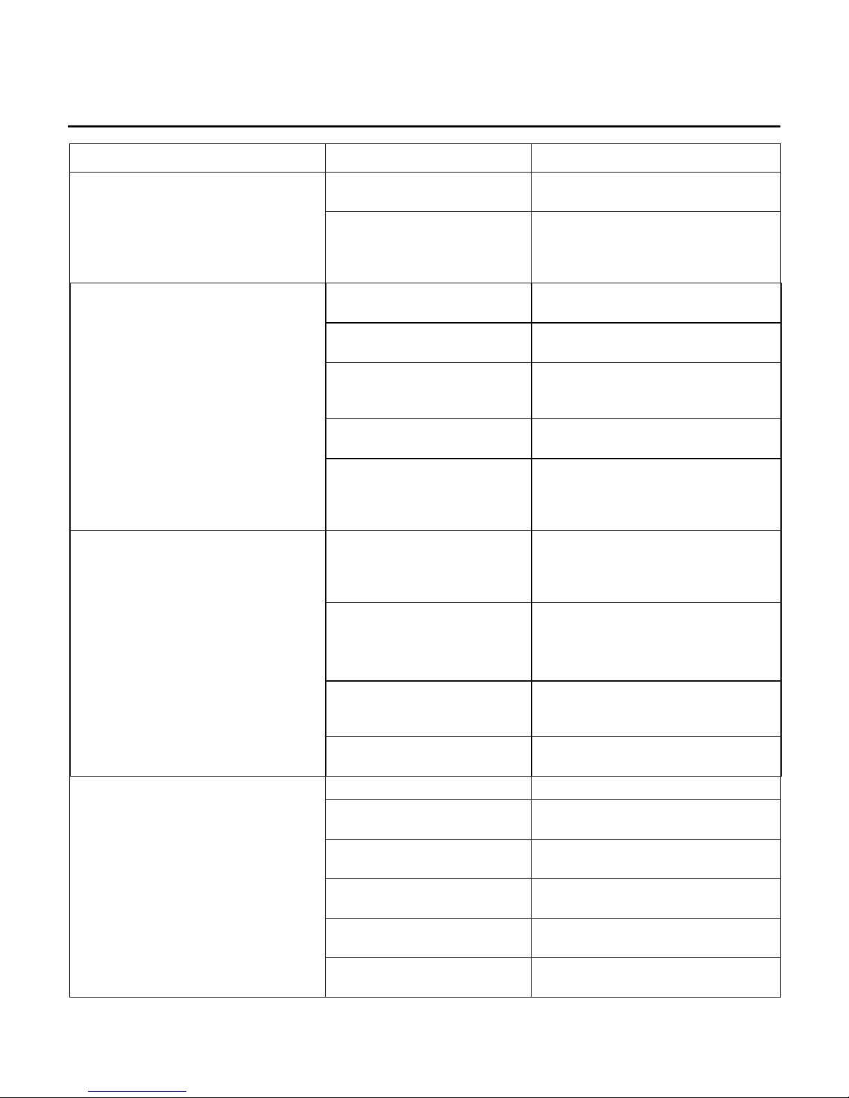
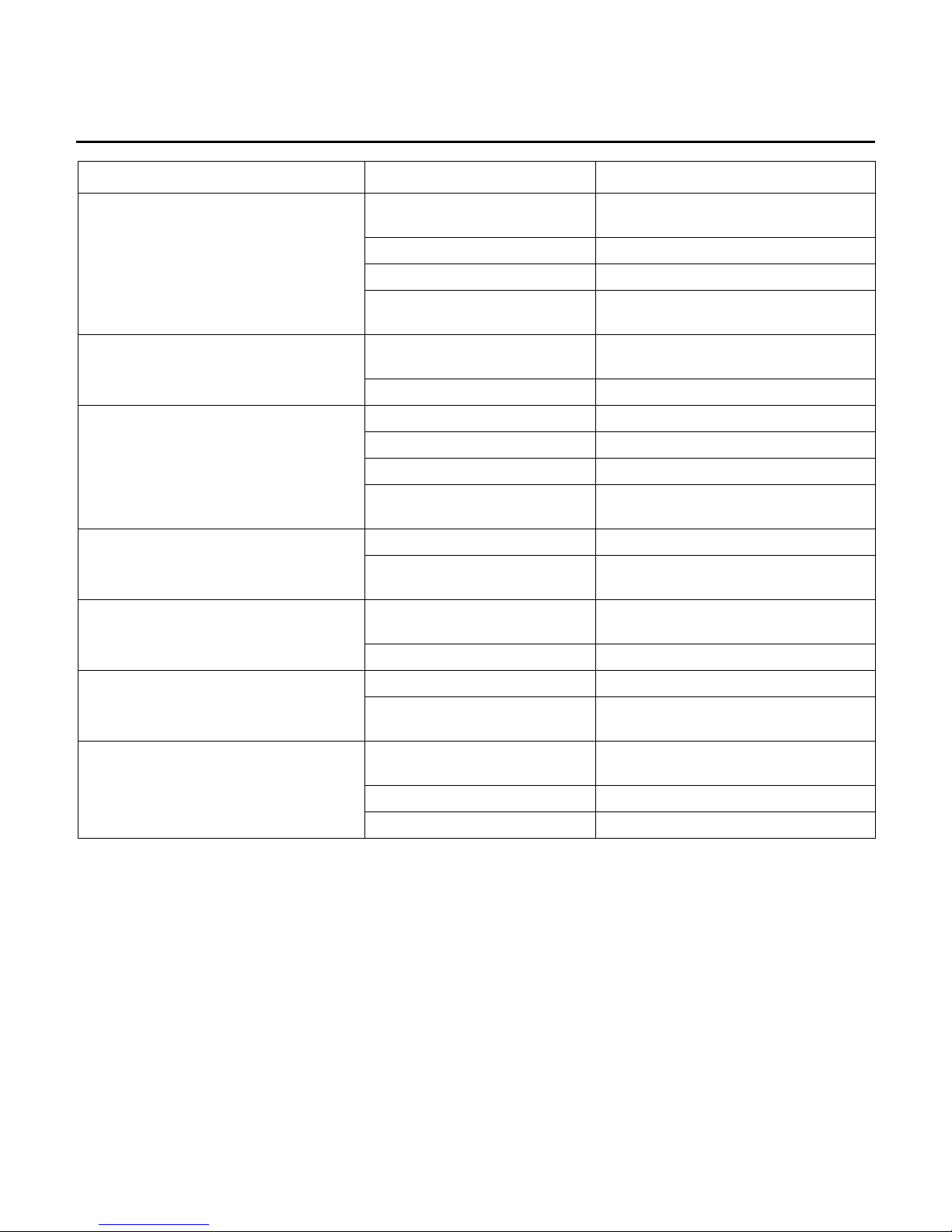
SYMPTOM PROBABLE CAUSE CORRECTIVE ACTION
No heart rate or, display reads (No
Heart Rate).
No heart rate reading Executive Diagnostic Mode to verify
performance of heart rate function.
Faulty cable connection Verify heart-rate cable is properly
connected.
Using an ohmmeter, verify continuity
at the main console cable. See wiring
diagram for pin location.
Malfunctioning
Handlebar/Lifepulse Grip
Assembly (include. Worn or
damaged heart rate lead)
Life Pulse handlebar Verify that the handlebar is
Handlebar/Lifepulse Grip
Assembly
Loose or malfunctioning heart
rate lead connection at Display
Console
Malfunctioning Display
Console
Wear or damage to grip Replace the handlebar assembly.
Channels do not change.
Sound does not change.
Faulty PCB Only one channel programmed Follow the setup procedures in the
No sound.
Key pad malfunction. Run Key pad test in diagnostics.
Interface PC board defective. Replace Interface PC board.
Key pad malfunction. Run Key pad test in diagnostics.
Interface PC board defective. Replace Interface PC board.
Faulty headphones. Replace headphones.
Faulty headphone jack
assembly.
Faulty cable to Headphone
jack assembly
Air/cable setting may not be
correct
Power applied prior to video
hookup
Replace Handlebar/Lifepulse
Assembly.
functioning. See diagrams.
Using an ohmmeter, verify continuity
between Lifepulse sensor and cable
connection. See wiring diagram for
pin location.
Dry wipe sensors.
Secure connection. Replace
malfunctioning Handlebar/Lifepulse
Grip Assembly
Test with substitute Display Console.
Replace malfunctioning Display
Console.
Replace if defective.
Replace if defective.
operator manual.
Replace headphone jack assembly.
Replace Headphone jack cable.
Follow the set up procedures in the
operators’ manual.
Power down, install video, and follow
channel instruction.
8
Lifecycle Recumbent Bikes LC95R, LC91R, LC85R, R9, R7, 95Ri, 93Ri, 90R, and 95Re
TROUBLESHOOTING GUIDE
SYMPTOM PROBABLE CAUSE CORRECTIVE ACTION
Unable to receive any channels when
using cable.
Snow and noise appear on the screen.
Screen is blank with audio beeps or
dark.
The wrong buttons activate when the
touch screen is touched.
screen is touched.
Screen does not turn ON and no
audio.
Air/cable setting may not be
correct.
Coax Cable may be bad. Replace Coax Cable.
Coax Cable may be unplugged Reconnect Cable.
Cable system may not be
producing clear signal
Air/cable setting may not be
correct.
Coax cable may be bad. Replace Coax cable.
LCD Back Light burned up. Replace LCD/Touch Screen.
Back Light power inverter bad Replace backlight inverter
LCD Screen failure Replace LCD/Touch Screen.
Problem on the single board
computer
Touch screen failure. Replace LCD/Touch Screen.Screen Does not respond to touch.
Problem with Single Board
Computer.
Touch Screen not calibrated
correctly
Touch Screen Damaged. Replace LCD/Touch Screen.
Touch Screen Damaged. Replace LCD/Touch Screen.No buttons activate when the touch
Failure On the single board
computer.
No power. Check Main Cable for 5 & 12VDC.
Faulty wire harness to console. Replace Wire Harness
LCD defective. Replace LCD\TOUCH screen
Follow the setup procedures in the
operator manual.
Notify installer.
Follow the setup procedures in the
operator manual.
Replace Single Board Computer.
Replace Single Board Computer.
Calibrate Touch Screen. Refer to
Diagnostics.
Replace the single board Computer.
Check wiring diagram pin locations.
9
Lifecycle Recumbent Bikes LC95R, LC91R, LC85R, R9, R7, 95Ri, 93Ri, 90R, and 95Re
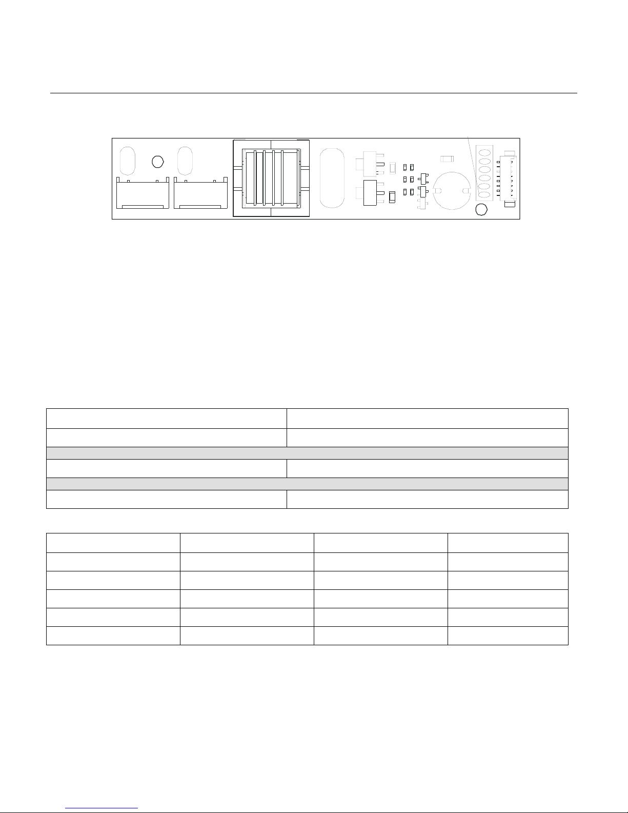
TROUBLESHOOTING GUIDE – TESTING THE INVERTER BOARD
Special Service Tools Required: Multi-meter
CAUTION! HIGH VOLTAGE ON CONNECTORS J2 AND J3
1.
J3
Remove the Integrated System Console from the Unit.
2. Remove Rear Cover from the Console Assembly.
3. Plug in Power Supply and Remote Control to the Console
4. Press the Power On Key on the Remote Control.
5. TEST NO. 1: Place the Red Lead from the multi-meter onto Test Point 1 and the Black Lead onto Test
Point 3. Voltage should be 12 Vdc (+/- .5V).
J2
Tes t Points
6
5
4
3
2
1
J1
6. TEST NO. 2: Place the Red Lead from the multi-meter onto Test Point 5 and the Black Lead to Test Point
3. Voltage should be 12 Vdc (+/- .5V)
PROBLEM SOLUTION
No Voltage on TP1 Replace Cable, Remote, or Main PC Board.
Voltage present on TP1 Replace the Inverter Board
Voltage on TP1 and TP2 but NO Voltage on TP5 Replace Cable between Inverter Board and Main PC Board
TEST POINT VOLTAGE DESCRIPTION PIN NUMBER
TP 1 & 2 12 Vdc VIN 1 & 2
TP 3 &4 0 Vdc Ground 3 & 4
5 12 Vdc Enable 5
5 0 Vdc Disable 5
6 Not Used Not Used 6/7/8
10

Lifecycle Recumbent Bikes LC95R, LC91R, LC85R, R9, R7, 95Ri, 93Ri, 90R, and 95Re
TROUBLESHOOTING GUIDE – TESTING THE POWER SUPPLY CABLE
Special Service Tools Required: Multi-meter
1. Unscrew the Retaining Nut securing the Power
Cable Plug. Remove the Cable.
2. Using a Multi-meter, touch the Red Lead to the
POSITIVE area on the Cable, which is the center
of the cable. Next touch the Black Lead to the
NEGATIVE area, which is the side of the inner
Cable. The voltage should read 12 Vdc.
Positive
Negative
Retaining nut
11

Lifecycle Recumbent Bikes LC95R, LC91R, LC85R, R9, R7, 95Ri, 93Ri, 90R, and 95Re
TROUBLESHOOTING GUIDE
Notes
12

Lifecycle Recumbent Bikes LC95R, LC91R, LC85R, R9, R7, 95Ri, 93Ri, 90R, and 95Re
SECTION IIA
DIAGNOSTIC MODES
FOR LED UNITS
Page
LC9500R ............................................................................................................................. 3
LC9100R Console............................................................................................................... 4
LC8500R Console............................................................................................................... 5
R9 Console ......................................................................................................................... 6
R7 Console ......................................................................................................................... 7
MAP..................................................................................................................................... 8
ENTRY LEVEL .................................................................................................................... 9
Test/Service - All LEDs And Keypad Test.......................................................................... 10
Test/Service - Walking LED Test ....................................................................................... 11
Test/Service - Miscellaneous 1 Test .................................................................................. 12
Test/Service - Miscellaneous 2 Test .................................................................................. 13
Test/Service - Port I/O Test................................................................................................ 14
Test/Service - Life Pulse Test ............................................................................................ 15
Test/Service - CSAFE Network Test .................................................................................. 16
Test/Service - EEPROM Test............................................................................................. 17
Test/Service - Telemetry Enable/Disable ........................................................................... 18
Test/Service - Language .................................................................................................... 19
Optional Settings - MAX Program Duration........................................................................ 20
Optional Settings - English/Metric Units............................................................................. 21
Optional Settings - WATT Display Enable/Disable............................................................. 22
Optional Settings - METS Display Enable/Disable............................................................. 23
Optional Settings - CAL/HR Display Enable/Disable.......................................................... 24
Optional Settings – WATTS Program Enable/Disable ....................................................... 25
Optional Settings - METS Program Enable/Disable........................................................... 26
Optional Settings - Statistics .............................................................................................. 27
Optional Settings – Entertainment Controls ....................................................................... 28
Optional Settings - Photo Shoot......................................................................................... 29
Notes.................................................................................................................................. 30
1

Lifecycle Recumbent Bikes LC95R, LC91R, LC85R, R9, R7, 95Ri, 93Ri, 90R, and 95Re
Notes
2

Lifecycle Recumbent Bikes LC95R, LC91R, LC85R, R9, R7, 95Ri, 93Ri, 90R, and 95Re
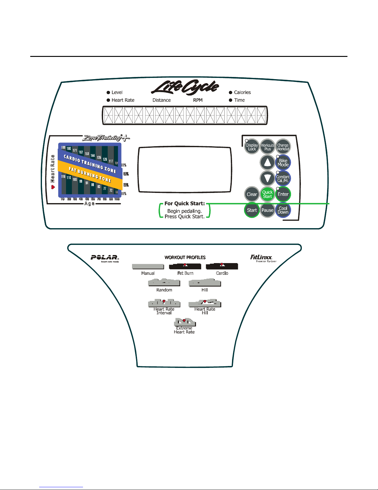
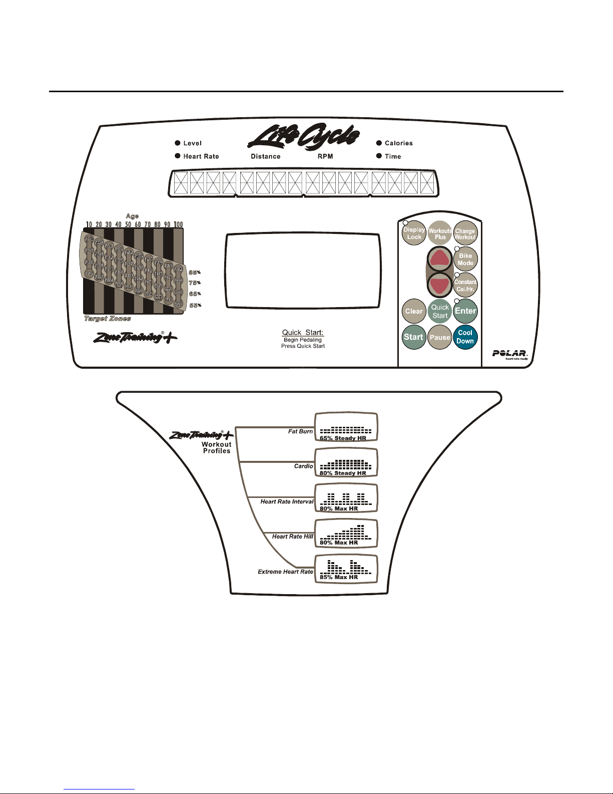
DISPLAY CONSOLE LC9500R
LC9500R
3
Lifecycle Recumbent Bikes LC95R, LC91R, LC85R, R9, R7, 95Ri, 93Ri, 90R, and 95Re
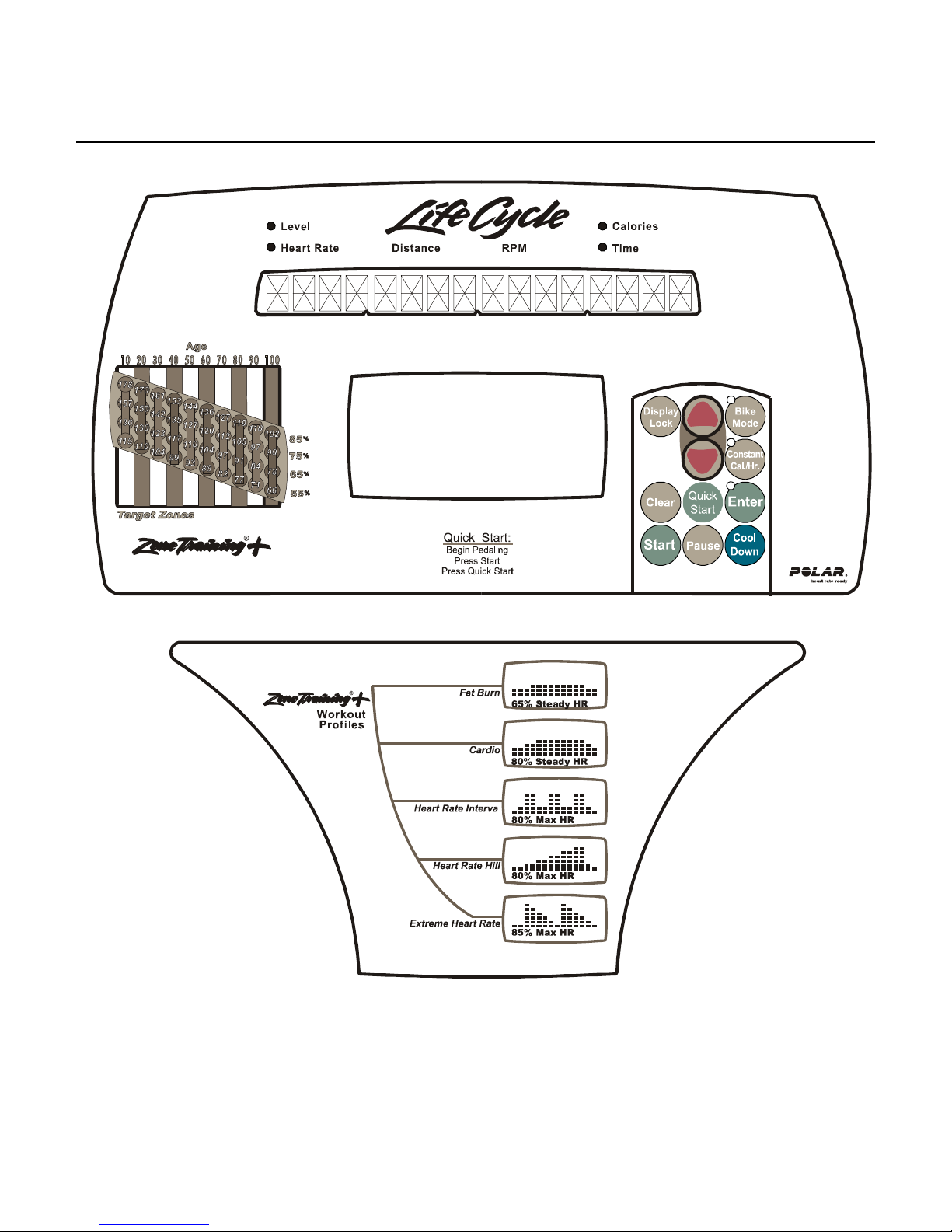
DISPLAY CONSOLE LC9100R
LC9100R
4
Lifecycle Recumbent Bikes LC95R, LC91R, LC85R, R9, R7, 95Ri, 93Ri, 90R, and 95Re
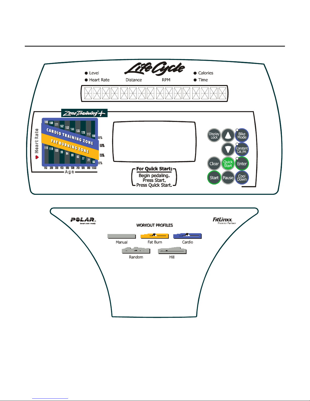
DISPLAY CONSOLE LC8500R
LC8500R
5
Lifecycle Recumbent Bikes LC95R, LC91R, LC85R, R9, R7, 95Ri, 93Ri, 90R, and 95Re
DISPLAY CONSOLE R9
R9
6
Lifecycle Recumbent Bikes LC95R, LC91R, LC85R, R9, R7, 95Ri, 93Ri, 90R, and 95Re
DISPLAY CONSOLE R7
R7
7

Lifecycle Recumbent Bikes LC95R, LC91R, LC85R, R9, R7, 95Ri, 93Ri, 90R, and 95Re
A
A
MAP
Test/service
Display Test
Walking Led
Port I/o Test
Language
All Led’s On
Keypad Test
Relay
Fld Kick
Units
lt. Voltage
lt Rpm
Entertainment
8
 Loading...