

Page 1

Life Fitness LCD Entertainment System
Customer Support Services
SERVICE MANUAL
Page 2

Life Fitness LCD Entertainment System
INTRODUCTION
HOW TO USE SERVICE MANUAL AND CONTACT CUSTOMER SUPPORT SERVICES
This service manual is applicable to Life Fitness LCD Entertainment System. Illustrations in this service manual
represent typical configurations and may differ slightly from actual equipment. The Service Manual provides safe and
efficient step-by-step service operations. This manual consists of:
TABLE OF CONTENTS
Section I
q TROUBLESHOOTING
Section II
q HOW TO...SERVICE AND REPAIR
Section III
q ELECTRONICS
Section IV
q MISCELLANEOUS
When an operating problem occurs, refer to troubleshooting guides to isolate the cause. When applicable, guides are
listed by problem symptom followed with suggestions of probable cause(s).
Once the source of problem is identified, consult the "How To..." guides for recommended repair procedures. "How
To..." sub-sections are organized by replaceable part or assembly name. For convenience, sub-section lists
recommended “Tools Required” to complete specific func tion. Refer to PARTS IDENTIFICATION to identify proper
name and number of part to order for repair of equipment.
A reproducible FAX order claim form is given in COMMUNICATING BY TELEFACSIMILE for convenient ordering of
service parts.
To order parts, cont act Life Fitness Customer Support Services.
Via FAX - 24 hrs. /day, 7 days/week.
Via telephone - Monday through Friday from 8:00 AM to 5:00 PM Central Standard Time.
Via post - At address cited.
To speed Life Fitness Customer Support Services response to your needs, please provide:
• Model number,
• Serial number,
• Symptom, and
• Part name and number
Before installing part, review "How To..." and follow step by step procedures recommended to install part safely and
efficiently. If you have questions or comments please telephone, FAX or, write us. We are:
LIFE FITNESS - CUSTOMER SUPPORT SERVICES
10601 Belmont Avenue; Franklin Park, IL 60131; U.S.A.
Telephone: 847.451.0036 Toll-free: 800.351.3737
FAX: 847.288.3702 Toll-free: 800.216.8893
i
Page 3

Life Fitness LCD Entertainment System
TABLE OF CONTENTS
SECTION I TROUBLESHOOTING PAGE
SCREEN WILL NOT TURN ON.................................................................................................. 3
CHANNELS DO NOT CHANGE ................................................................................................. 3
SOUND DOES NOT CHANGE ................................................................................................... 3
NO SOUND.............................................................................................................................. 3
UNABLE TO RECEIVE ANY CHANNELS WHEN USING CABLE ................................................. 3
SNOW AND NOISE APPEAR ON THE SCREEN........................................................................ 3
HOW TO…TEST THE INVERTER BOARD.................................................................................. 4
HOW TO…TEST THE POWER SUPPLY .................................................................................... 5
NOTES.................................................................................................................................... 6
SECTION II HOW TO REPLACE
TV ASSEMBLY ......................................................................................................................... 3
HEADPHONE JACK ................................................................................................................... 4
REMOTE CONTROL .................................................................................................................. 5
INVERTER BOARD ................................................................................................................... 6
MAIN PC BOARD ...................................................................................................................... 7
CONNECTOR BRACKET ........................................................................................................... 8
COAX/POWER CABLES (UPRIGHT BIKE)................................................................................... 9
COAX/POWER CABLES (RECUMBENT BIKE)............................................................................ 12
COAX/POWER CABLES (S TEPPER).......................................................................................... 14
COAX/POWER CABLES (CROSS-TRAINER - BLACK) ................................................................. 15
COAX/POWER CABLES (TREADMILL - SILVER) ......................................................................... 16
COAX/POWER CABLES (TR91, 95HR, 97HR - BLACK)................................................................ 19
NOTES ..................................................................................................................................... 20
SECTION III ELECTRONIC OVERVIEW AND WIRI NG BLOCK DIAGRAM
MAIN POWER CONTROL BOARD............................................................................................. 3
INVERTER BOARD PIN LAYOUT.............................................................................................. 4
ii
Page 4

Life Fitness LCD Entertainment System
TROUBLESHOOTING GUIDE
Notes:
2
Page 5

4
Page 6

Test Points
Life Fitness LCD Entertainment System
How To...Test the Inverter Board
Special Service Tools Required: Multi -meter
6
5
4
3
2
J3 J2
1. Remove the Entertainment System Console from the Unit.
2. Remove Rear Cover from the Console Assembly.
3. Plug in Power Supply and Remote Control to the Console
4. Press the Power On Key on the Remote Control.
5. TEST NO. 1: Place the Red Lead from the multi-meter onto Test Point 1 and the Black Lead onto Test Point 3.
Voltage should be 12 Vdc (+/- .5V).
6. TEST NO. 2: Place the Red Lead from the multi-meter onto Test Point 5 and the Black Lead to Test Point 3.
Voltage should be 12 Vdc (+/- .5V)
1
PROBLEM SOLUTION
J1
No Voltage on TP1 Replace Cable, Remote, or Main PC Board.
Voltage present on TP1 Replace the Inverter Board
Voltage on TP1 and TP2 but NO Voltage on TP5 Replace Cable between Inverter Board and Main PC Board
TEST POINT VOLTAGE DESCRIPTION PIN NUMBER
TP 1 & 2 12 Vdc VIN 1 & 2
TP 3 &4 0 Vdc Ground 3 & 4
5 12 Vdc Enable 5
5 0 Vdc Disable 5
6 Not Used Not Used 6/7/8
5
Page 7

Life Fitness LCD Entertainment System
Retaining
Nut
Positive
Negative
How To...Test the Power Supply
Special Service Tools Required: Multi -meter
1. Unscrew the Retaining Nut securing the Power Cable
Plug at the back of the Console Assembly and remove
the Cable from the Console.
2. Using a Multi-meter, touch the Red Lead to the
POSITIVE area on the Cable, which is the center of the
cable. Next touch the Black Lead to the NEGATIVE
area, which is the side of the inner Cable. The voltage
should read 12 Vdc.
Power
Cable
Retaining nut
6
Page 8

Life Fitness LCD Entertainment System
NOTES
7
Page 9

Life Fitness LCD Entertainment System
SECTION II
HOW TO…
SERVICE AND REPAIR GUIDE
1
Page 10

Life Fitness LCD Entertainment System
NOTES
2
Page 11

TV Console
Life Fitness LCD Entertainment System
How To Replace the TV Assembly
Special Service Tools Required: NONE
1. Disconnect three cables from the back of the
Console. Both the Power Cable and the Coax
Cable are screw on connectors. The Cable from
the Remote uses a connector that clips into the
receptacle connector.
2. Remove the four screws securing the TV
Console to the Support Frame.
3. Remove the TV Console Assembly.
4. Install a new TV Console Assembly in
reverse order.
5. For channel reprogramming refer to
Operation Manual.
Mounting
Screws (4)
Support
Frame
3
Page 12

TORX Screw
Remote
Door
Life Fitness LCD Entertainment System
How To... Replace the Headphone Jack
Special Service Tools Required: NONE
Note: The Headphone Jack can be removed without
removing the Remote Control from Unit.
1. Remove the TORX Screw from the base of the Remote
Control.
2. Swing the Door down which exposes the
Headphone Jac k.
3. Using a pair of long nose pliers, pull the
Headphone Jack out of the Remote Control.
4. Discard the faulty Headphone Jack.
5. Install new Headphone Jack in reverse order.
Control
4
Headphone
Jack
Page 13

Upright Bike
Treadmills
Recumbent
Stair Climber
Cross-Trainer
Life Fitness LCD Entertainment System
How To... Replace the Remote Control
Special Service Tools Required: NONE
Note: The Remote Control Unit can be removed without removing TV Assembly. Refer to the illustrations
above to identify Remote Control Location on each Unit. On Treadmills the remote is mounted between the
Life Pulse Sensor and the Cover on the left side of the Handlebar.
Bike
Remote
Control
Locations
Remote
Control
Treadmills
1. Cut the Wire Ties securing the Remote Control to the
equipment.
2. Remove the Cup Holders.
3. Remove the Console Assembly.
4. Unplug the Cable from the Remote at the back of the TV
Console.
5. Secure the Rem ote Control Assembly with Wire Ties and
cut off the excess.
6. Install new Remote at the locations shown above.
Cross-Traner
5
Page 14

Life Fitness LCD Entertainment System
How To... Replace the Inverter Board
Special Service Tools Required: NONE
CAUTION! Before replacing Circuit Board(s), ground yourself to the machine using an anti -static ground
strap.
1. Remove the TV Assembly. See “How To …” in this section.
2. Remove four screws securing the
Back Cover of the TV Console, and
then separate the two console
halves.
3. Lift bac k the Protective Cover
exposing the Inverter Board, and
then unplug the three cables.
4. Remove two Torx Screws securing the
Inverter Board from the PC board.
5. Remove the Inverter Board.
Note: If the protective cover needs
replacement, then do so at this time.
6. Install new Inverter Board in reverse
order.
7. Check for power………………
Note: Make sure to re -install the Inverter
Board Protective Cover.
Inverter Board
Protective Cover
Inverter
Board
Inverter Board
TORX Screws(2)
6
Page 15

Back Cover
Back Cover
Cable
LCD Ribbon
Life Fitness LCD Entertainment System
How To... Replace the Main PC Board
Special Service Tools Required: NONE
CAUTION! Before replacing Circuit Board(s), ground
yourself to the machine using an anti -static ground
strap.
1. Remove the TV Assembly. See “How To …” in this
section.
2. Remove four screws securing the back of the TV
Console, and then separate the two console halves.
3. Unplug five cables connected to the PC
board as follows:
• Power Cable
• Antenna Coax Cable
• Remote Cable
• Inverter Power Cable
• LCD Ribbon Cable
4. Remove four screws securing the Main PC Board to
the bracket and lift out the Main PC Board.
5. Install new Main PC Board in reverse order.
6. For channel re-programming refer to the Operation
Manual.
Power
Cable
Antenna
Coax Cable
Screws(4)
Inverter
Power
Cable
Cable
Remote
Main PC
Board
Phillips
Screws(4)
7
Page 16

Life Fitness LCD Entertainment System
Back Cover
Back Cover
Screw
How To... Replace the Connector Bracket
Special Service Tools Required: NONE
CAUTION! THIS PC BOARD CONTAINS STATIC SENSITIVE
COMPONENTS. MAKE CERTAIN YOU ARE PROPERL Y
GROUNDED USING AN ANTI-STATIC STRAP BEFORE
REPLACING CIRCUIT BO ARD. ALWAYS HANDLE THE
CIRCUIT BOARD FROM THE EDGES IF POSSIBLE TO AVOID
DAMAGING ELECTRONIC COMPONENTS.
1. Remove the TV Assembly. See “How To …” in this section.
2. Remove four screws securing the back of the TV Console,
and then separate the two halves.
3. Remove the two Torx Screws securing the
Connector Bracket.
4. Unplug three cables from the Main PC Board as
follows:
• Power Cable
• Coax Cable (75 Ohms)
• Remote Cable
5. Remove the Connector Bracket.
6. Install new Connector Bracket in reverse order.
Main PC
Board
Coax Cable
(75 Ohms)
Screws(4)
Power
Cable
8
TORX
Screw
Remote
Cable
Connector
Bracket
TORX
Page 17

Seat Post Covers
Life Fitness LCD Entertainment System
How To... Replace the COAX/Power Cables (Upright Bike)
Special Service Tools Required: NONE
1. Remove the Mounting Screw on the Right Side
Seat Cover and then remove the Seat Post
Covers.
2. Remove three screws from the Right Crank
Arm, and then remove the Right Crank Arm
from the Crank Hub with the Pedal attached.
3. To remove the Right Side Shroud,
remove eight screws as follows:
• Four screws at the bottom of the
Shroud
• One at the top rear of the Shroud. This
screw is secured into the Left Side
Shroud.
• Three screws, as shown, which secure
the Right Shroud to the Frame.
Seat Post
Cover
Screw
Shroud to
Frame Screw (3)
(12-15 in lbs)
9
Crank Hub
Screws(3)
(15-20 ft lbs)
Shroud-to-Shroud
Screws (5)
(12-15 in lbs)
Page 18

Crank Hub
Screws(3)
(15-20 ft lbs)
Screws(4)
Console Assembly
Life Fitness LCD Entertainment System
How To... Replace the COAX/Power Cables (Upright Bike) - Continued
Special Service Tools Required: NONE
4. Remove three screws from the left crank
hub, and then remove the left crank arm
from the crank shaft with pedal attached.
5. Remove the three Shroud Screws from
the upper half of the Left Side Shroud.
6. Remove four mounting screws from the back of
the Console at the Console Support.
7. Lift the Console up just enough to disconnect the
Main Wiring, and then remove the Console
Assembly with the Accessory Tray.
Plug
w/Accessory Tray
Left Shroud
Shroud Screw (3)
to Frame
(12-15 in lbs)
10
Phillip
Page 19

Torque
specified torque.)
Coax Cable
Main Console Cable
Life Fitness LCD Entertainment System
How To... Replace the COAX/Power Cables (Upright Bike) - Continued
Special Service Tools Required: NONE
8. Unplug the Main Console Cable from the Power Control Board
(Connector P2).
9. Remove the Mounting Screws securing the I-Beam Joint to the Console
Support Assembly and separate it from the I-Beam.
10. Remove four mounting screws securing the I-Beam Joint to the Frame,
and lift the Console Support Assembly and I-Beam out of the Frame.
11. Remove the side covers from the I-Beam Joint.
12. If replacing the Power Cable, then cut the Cable Ties securing the
Transformer to the Front Stabilizer.
13. Before removing any cables, attach a fish tape to the end of the COAX
Cable or Power Cable. Pull the old cable out from the bottom of the
Unit. Take off the old cable from the fish tape and attach the new cable.
Carefully pull the fish tape up and guide the new cable up until it comes
out through the top of the frame.
14. If the Power Supply was replaced, secure with Cable Tie to the
Stabilizer.
15. Install parts in reverse order.
Power Cable
I-Beam
Mounting
Screws
Polar Cable
Console Support
Mounting Screws(4)
Handlebar
Cover, RT
I-Beam Joint
HR Sensors
Cable
28-30 ft lbs
(A Torque Wrench
must be used in
order to ensure
Handlebar
Cover, LT
11
Page 20

Shroud Screrws(7)
End
Cap
End Cap
Screws(2)
Life Fitness LCD Entertainment System
How To... Replace the COAX/Power Cables (Recumbent Bike)
Special Service Tools Required: NONE
Torque 12-15 in lbs
Left Shroud
Crank Arm Screws(3)
Torque 15-20 ft lbs
Right Crank Arm
w/Pedal
1. Remove three screws from the Right Crank Hubs, and then remove the Crank Arms with Pedals attached.
2. Remove two screws from the End Cap at the end of the Frame, which allows access to the left and right side
Shroud Screws.
3. Remove the right side Shroud Screws, and then remove the Right Side Shroud.
12
Page 21

Main Wiring Cable
Power Cable
Life Fitness LCD Entertainment System
How To... Replace the COAX/Power Cables (Recumbent Bike) - Continued
Special Service Tools Required: NONE
4. Remove four Mounting Screws from the back of
the Console at the Console Support.
5. Lift the Console up just enough to disconnect the
10-pin Main Wiring Connector, and if equipped,
the 4-pin Heart Rate Cable.
6. Remove the Console from the Console Support.
7. Disconnect the COAX Cable or Power Cable from
the LCD.
8. Cut the Cable Ties securing the Transformer to
the Front Stabilizer.
9. Before removing any cables, attach a fish tape to
the end of the COAX Cable or Power Cable. Pull
the old cable out from the bottom of the Unit. Take
off the old cable from the fish tape and attach the
new cable. Carefully pull the fish tape up and
guide the new cable up until it comes out through
the top of the frame.
10. Secure the Transformer to the Front Right
Stabilizer using Cable Tie.
11. Install parts in reverse order.
Coax Cable
Console Support
Console
Heart Rate Cable
w/4-Pin Connector
w/10-Pin Connector
Console
Mounting
Screw(4)
13
Page 22

Right Shroud
Mono-Column
Jack Nut
Jack
Main Wiring Cable
10-Pin Connector
Heart Rate Cable
4-Pin Connector
Coax Cable
Power Cable
Console
Life Fitness LCD Entertainment System
How To... Replace the COAX/Power Cables (Stepper)
Special Service Tools Required: NONE
1. Remove four screws securing the Mono-Column Shroud.
2. Lift the Mono -Column Shroud up the Mono-Column and secure it up
out of the way.
3. Remove five screws from the Right Side Shroud, and then remove
the Shroud from the machine.
4. Remove four screws securing the Left Side Shroud. Carefully pull
the Shroud back just enough to reach in and disconnect The Power
Jack Lead Wire from the PCB Board, and then remove the Left Side
Shroud.
Shroud
Left Shroud
5. Remove four mounting screws securing the console
and tray assembly to the Console Support.
6. Disconnect the cables at the back of the console.
7. Before removing any cables, attach a fish tape to the
end of the COAX Cable or Power Cable. Pull the old
cable out from the bottom of the Unit. Take off the old
cable from the fish tape and attach the new cable.
Carefully pull the fish tape up and guide the new cable
up until it comes out through the top of the frame.
8. Reassemble in reverse order.
Power
Power
w/
w/
14
Console Support
Page 23

4 Pin HR Sensors cable
Power supply
Power supply
Life Fitness LCD Entertainment System
How To... Replace the COAX/Power Cables (Cross- Trainer - Black)
Special Service Tools Required: NONE
1. Remove the four Mounting Screws from under
the Console.
2. Lift the Console up enough to disconnect the
16-pin, 3-pin, and 4-Pin connectors (CT9500),
and then place the Console aside.
3. Before removing any cables, attach a fish tape
to the end of the COAX Cable or Power Cable.
Pull the old cable out from the bottom of the
Unit. Take off the old cable from the fish tape
and attach the new cable. Carefully pull the fish
tape up and guide the new cabl e up until it
comes out through the top of the frame.
4. Reinstall Console in reverse order.
16 PIN Main Cable
Power Cable
Coax Cable
Mounting Screws (4)
3 Pin Polar Cable
Ct95 Only
Transformer
Line cord
Coax Cable
15
Page 24

Life Fitness LCD Entertainment System
Console PC Board/
How To... Replace the COAX/Power Cables (Treadmill - Silver)
Special Service Tools Required: NONE
1. Remove eight screws from the back of the
Console, and lift the Bezel Assembly just enough
to unplug all cables connected at the top of the
PCB, then remove the Bezel Assembly.
2. Remove four mounting screws securing each
Accessory Tray, and lift out the Accessory Trays.
Overlay Bezel Assembly
Left Cup
Holder
Right Cup
Holder
16
Page 25

Inside Upright
Upright, RT
Motor
Cover
Life Fitness LCD Entertainment System
How To... Replace the COAX/Power Cables (Treadmill - Silver) - Continued
Special Service Tools Required: NONE
3. Remove the left and right inside Upright Covers.
4. Remove four screws from the Front Cover, and
then remove the Front Cover from the front of the
unit.
5. Remove four Motor Cover screws, and then lift
off the Motor Cover from between the Upright
Supports.
Upright, LT
Inside Upright
Cover, Left
Cover, Right
Front
Cover
Motor
Cover
17
Page 26

Power Supply
Line Cord
Wire Ties
Life Fitness LCD Entertainment System
How To... Replace the COAX/Power Cables (Treadmill - Silver) - Continued
Special Service Tools Required: NONE
6. Disconnect the COAX Cable or Power Cable from
the LCD.
7. Cut the cable Ties securing the Transformer to the
Treadmill Frame.
8. Before removing any cables, attach a fish tape to
the end of the COAX Cable or Power Cable. Pull
the old cable out from the bottom of the Unit. Take
off the old cable from the fish tape and attach the
new cable. Carefully pull the fish tape up and
guide the new cable up until it comes out through
the top of the frame.
9. Cable Tie the Transformer to the Fame.
10. Install all parts in reverse order.
Transformer
18
Page 27
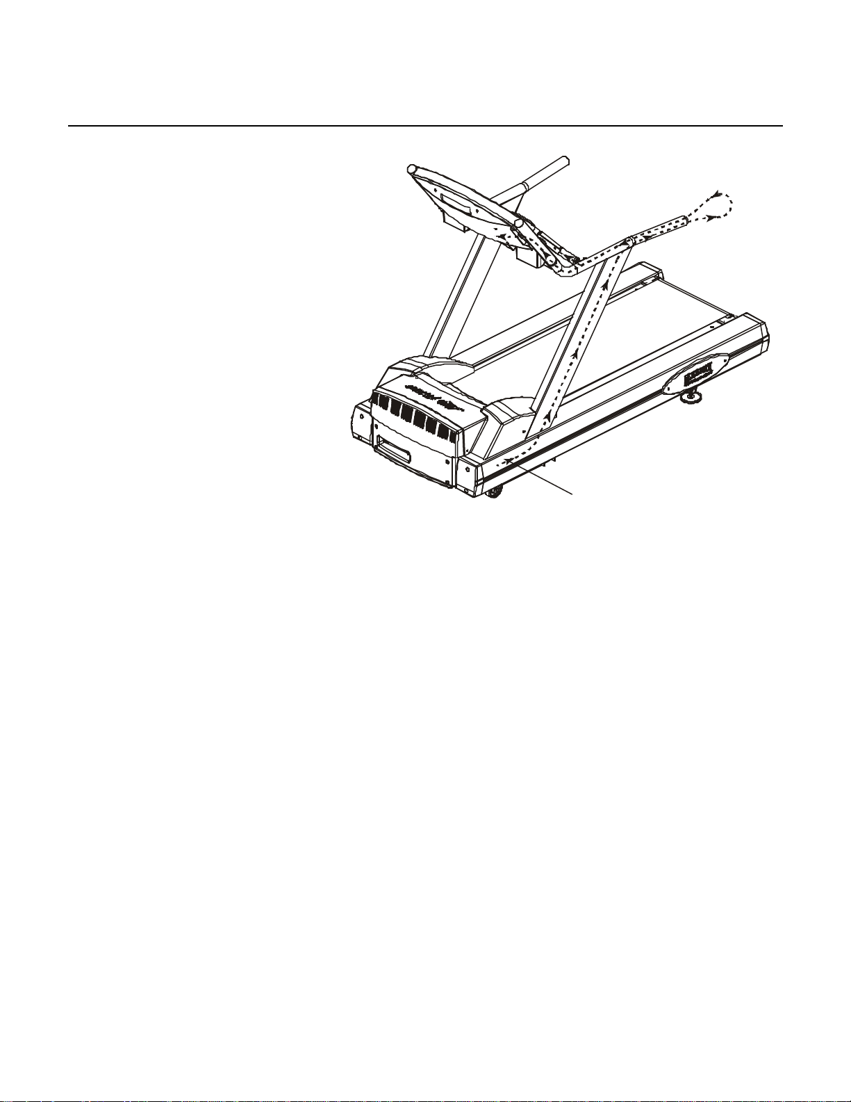
Life Fitness LCD Entertainment System
Cable
Routing
How To... Replace the COAX/Power Cables (TR91, 95HR, 97HR - Black)
Special Service Tools Required: NONE
1. Turn the unit power OFF at the
switch, and then unplug the line cord
at the wall outlet.
2. Remove eight screws from the back
of the console.
3. Disconnect all cable connectors from
the circuit board.
4. Remove six mounting screws
securing the display console to the
Tube Extensions, and then remove
the display console.
5. Remove the left Tube Extension from
the cables. Route out the cables from
the tube.
6. Remove eight screws from the
Handle Bar, and then remove the
handle bar.
7. Remove the Motor Cover and
disconnect the Main Wiring Harness Connector from the Wax Lift Board.
8. If equipped with a fan on the side frame, remove all cables connected to the Wax Lift Board and to the Motor
Controller.
9. Remove four screws holding in the Motor Controller, and then remove it.
10. Remove the two screws securing the Fan Bracket.
11. Remove three mounting bolts at the base of the left handrail support.
12. Lift off the left handrail while routing out the cable from the frame.
13. Remove the Left Handle Bar End Cap, and then pull out the Main Wiring Harness and discard.
14. Install the new Coax and Power Cable in reverse order. With the left handle bar end cap removed, route the
cable out the end of the handle bar, then re -route back out to the top of the handle bar.
19
Page 28

Life Fitness LCD Entertainment System
NOTES
20
Page 29

Life Fitness LCD Entertainment System
SECTION III
ELECTRONIC OVERVIEW
WIRING BLOCK DIAGRAM
AND
1
Page 30

Life Fitness LCD Entertainment System
NOTES
2
Page 31
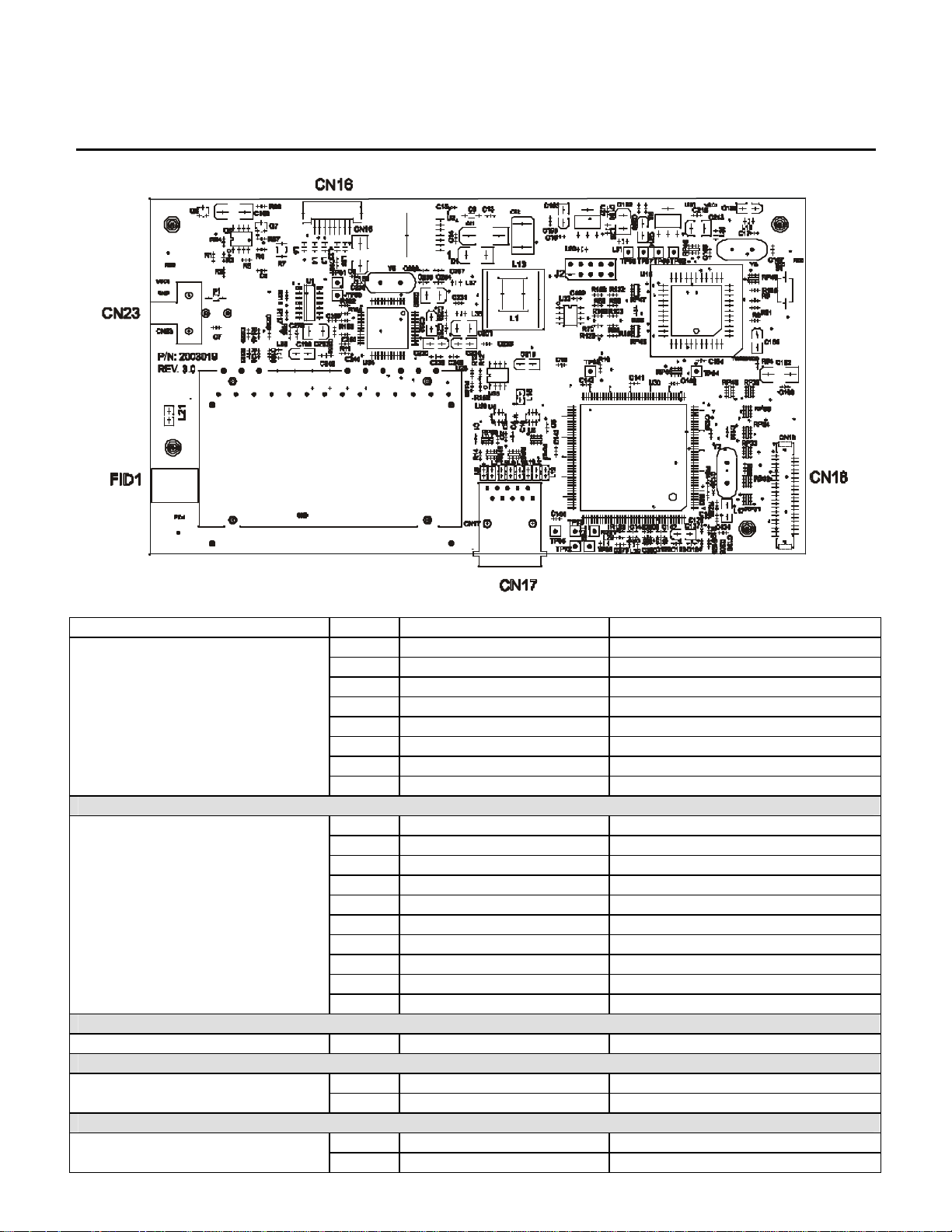
Life Fitness LCD Entertainment System
Main Power Control Board
CONNECTOR PIN FUNCTION VOLTAGE
CN16 – Inverter Power
CN17 – Remote Control and
Headphone Output
CN18 1-41 LCD Ribbon Cable Communication to LCD Screen
1 Ground Ground
2 Ground Ground
3 Vin 12 Volts DC
4 Vin 12 Volts DC
5 Enable 0-5 Volts DC
6 N/C N/C
7 N/C N/C
8 N/C N/C
1 - 2 - 3 - 4 - 5 - 6 - 7 - 8 - 9 - 10 - -
1 Vin 12 Volts DC CN23 Main Power Input
2 Ground Ground
1 - - FID1 Antenna Input
2 Ground Ground
3
Page 32

Life Fitness LCD Entertainment System
J1
Inverter
Inverter Board Pin Layout
Board
J3 J2
CONNECTOR PIN FUNCTION VOLTAGE
J1
J2
J3
1 Vin 12 Volts DC
2 Vin 12 Volts DC
3 Ground Ground
4 Ground Ground
5 Enable 0-5 Volts DC
6 N/C N/C
7 N/C N/C
8 N/C N/C
1 AC-out 1500 VAC Unload
550 VAC Loaded
2 AC-com -
1 AC-out 1500 VAC Unload
550 VAC Loaded
2 AC-com -
5
Page 33

Zone Trainer and Heart Rate Zone Training are trademarks of Brunswick Corporation. Any use of these trademarks, without the express
©2004 Brunswick Corporation. All rights reserved. Life Fitness is a registered trademark of Brunswick Corporation.
written consent of Brunswick Corporation, is forbidden.
M051-00K32-A036 – 02/04
 Loading...