

Page 1
8210 LAT PULLDOWN/LOW ROW
Part # 6776201
ASSEMBLY INSTRUCTIONS
Revision:7/9/981
Page 2
IMPORTANT NOTES
Please note:
* Thank you for purchasing the LIFE FITNESS 8210 LAT PULLDOWN/LOW ROW. Please read
these instructions thoroughly and keep them for future reference. This product must be assembled
on a flat, level surface to assure its proper function.
* We recommend cleaning your product (pads and frame) on a regular basis, using warm soapy
water. Touch-up paint can be purchased from your LIFE FITNESS customer service representative at (800) 328-9714.
There is a risk assumed by individuals who use this type of equipment. To minimize risk, please
follow these rules:
1. Inspect equipment daily. Tighten all loose connections and replace worn parts immediately.
Failure to do so may result in serious injury.
2. Do not allow minors or children to play on or around this equipment.
3. Exercise with care to avoid injury.
4. If unsure of proper use of equipment, call your local LIFE FITNESS STRENGTH distributor or
call the LIFE FITNESS STRENGTH customer service department at (800) 328-9714.
5. Consult your physician before beginning any exercise program.
Tools Required for Assembly
* Rubber mallet or hammer
* 3/4” wrench, 9/16” wrench
* Ratchet with 3/4” and 9/16” sockets
* 5/32”, 3/16”, 7/32” Allen wrenches
* Adjustable wrench
* Tape measure
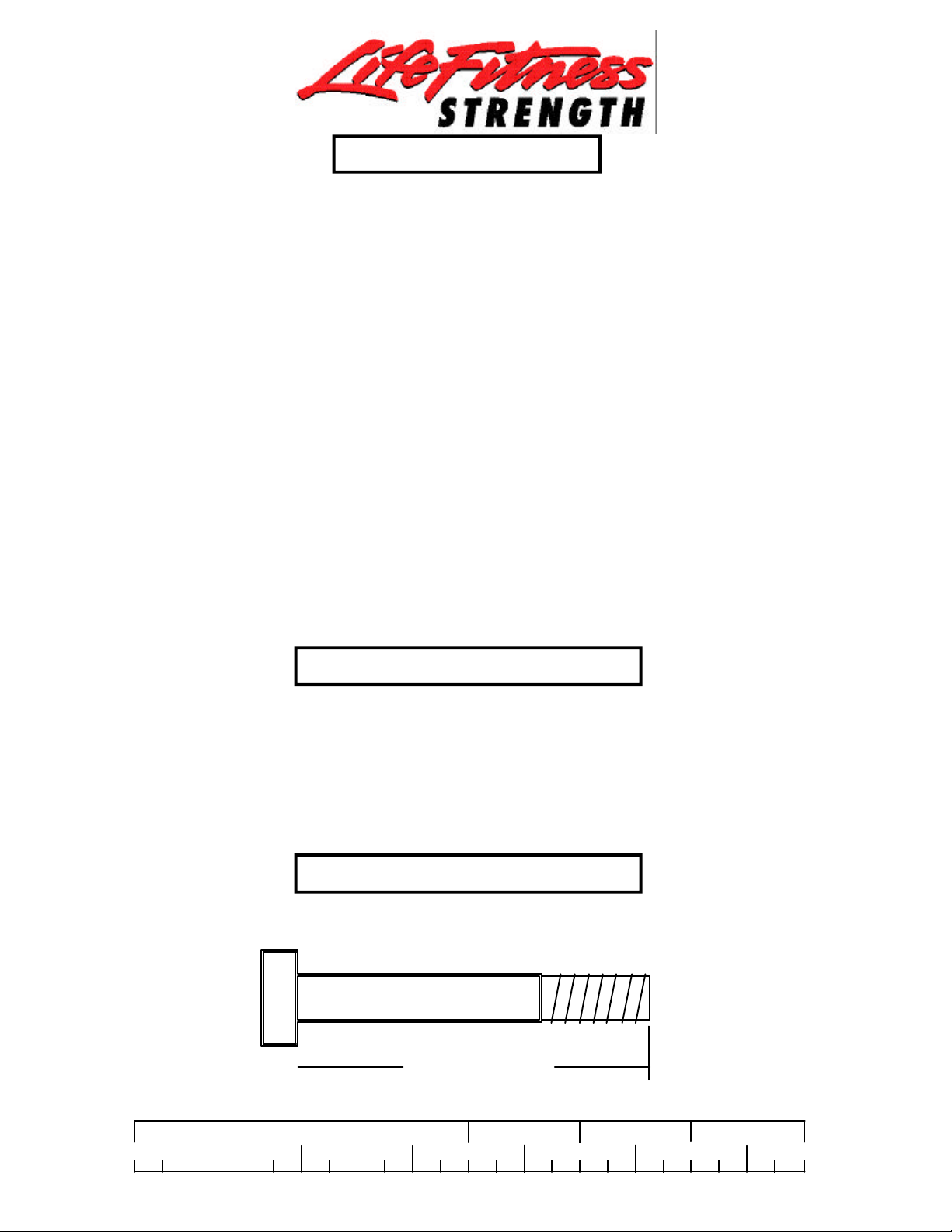
Bolt Length Ruler
NOTE: BOL T LENGTH IS MEASURED FROM THE UNDERSIDE OF THE HEAD OF THE BOL T.
BOLT LENGTH
BOLT LENGTH RULER:
1/2 1/2 1/2 1/2 1/2 1/2
0
1
2
3 4 5
2
6
Page 3
PARTS LIST
KEY
1
2
3
4
5
6
7
8
9
10
11
12
13
14
15
16
17
18
19
20
21
PART #
6775503
6775103
6774602
6778103
6774302
6792403
6777703
6489902
6275301
6678201
6781701
6781501
3116101
6772301
6523401
6677204
6764901
3102917
3102910
3102901
3102902
DESCRIPTION
BENCH FRAME
TOP BOOM
KNEE SUPPORT
UPRIGHT
FOOT SUPPORT
TOWER
TOWER BRACE
2 X 7-1/4” PLATE
LAT BAR
DOUBLE D CHROME HANDLE
112-3/4” LOW ROW CABLE
122-3/4” LAT CABLE
4-1/2” PULLEY
21-1/2” TUBE
GUIDE ROD
SEAT PAD
ROLLER PAD
1/2 X 4" BOLT
1/2 X 3" BOLT
3/8 X 1-1/4”
3/8 X 2-1/4" BOLT
QTY
1
1
1
1
1
1
1
2
1
1
1
1
7
1
2
1
2
12
2
1
3
KEY
22
23
24
25
26
27
28
29
30
31
32
33
34
35
36
37
38
39
40
41
42
PART #
3102922
3202401
3102502
3102501
3102801
3102802
6480301
6412001
3103801
3103302
3103304
6284501
6714601
6214401
6214501
3108002
3105301
6382301
6703801
6189501
6791102
DESCRIPTION
3/8 X 2-3/4” BOLT
3/8 X 1” BUTTON HEAD
1/2 “ WASHER
3/8" WASHER
1/2" LOCKNUT
3/8" LOCKNUT
3/8" FLANGE SPACER
3/8" SPRING PIN
5/16” SNAP HOOK
13/16” SHAFT COLLAR
1-5/16” SHAFT COLLAR
WEIGHT STACK SHAFT
HEAD PLATE
SELECTOR PIN
WEIGHT PLATE
WEIGHT STACK CUSHION
5/8” CAP PLUG
PLATE BUSHING (10 COUNT)
WEIGHT STACK LABELS LBS.
WEIGHT STACK LABELS (1-25)
SHROUD
QTY
7
5
12
9
13
8
8
1
2
2
2
1
1
1
20
2
2
4
1
1
1
3
Page 4
38
26
6
24
1
18 1/2 X 4”
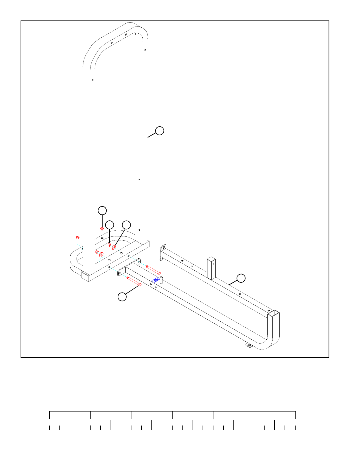
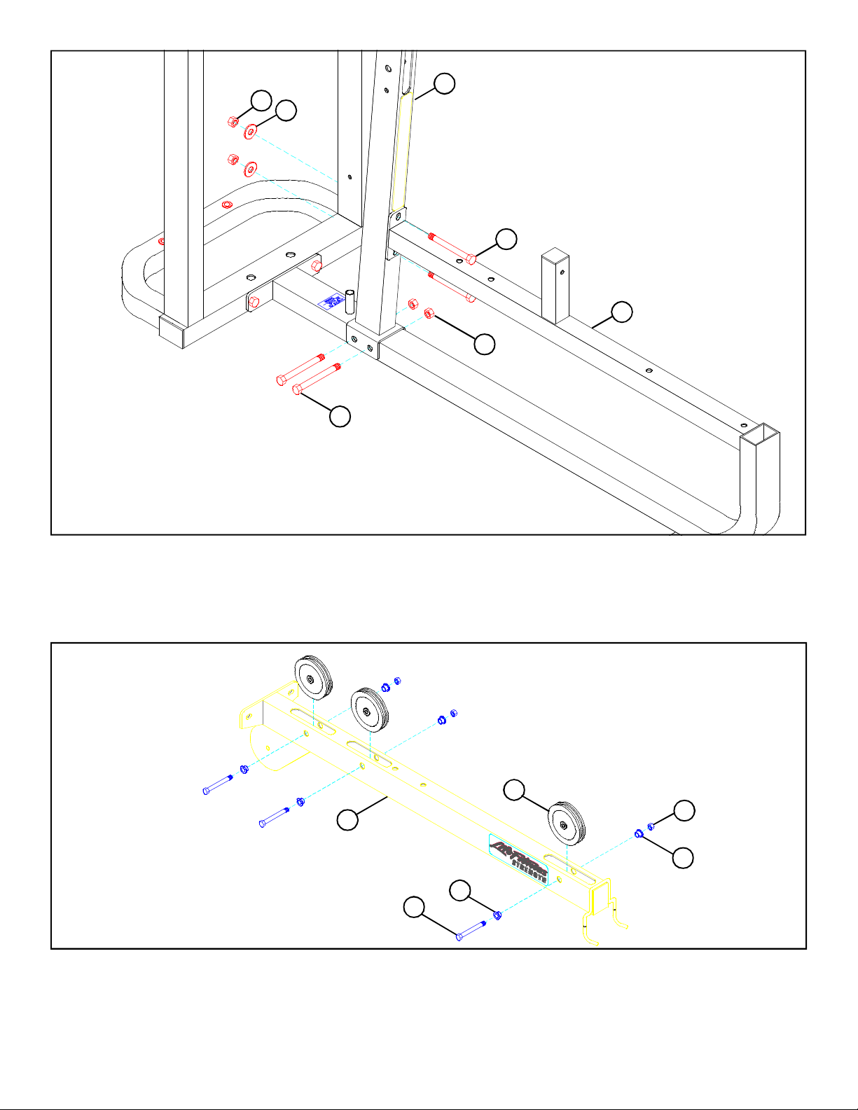
FIGURE 1
STEP 1:
• LOOSELY assemble the BENCH FRAME (1) to the TOWER (6) using two 1/2 X 4” BOLTS (18),
two 1/2” WASHERS (24), and two 1/2” LOCK NUTS (26) as shown in FIGURE 1.
• If the machine is not going to be bolted to the floor, insert two 5/8” CAP PLUGS (38) into the TOWER
(6) as shown in FIGURE 1.
1/2 1/2 1/2 1/2 1/2 1/2
0
1
2
3 4 5
4
6
Page 5
26
4
24
18 1/2 X 4”
1
26
18 1/2 X 4”
FIGURE 2
STEP 2:
• LOOSELY assemble the UPRIGHT (4) to the BENCH FRAME (1) using four 1/2 X 4” BOLTS (18),
two 1/2” WASHERS (24), and four 1/2” LOCK NUTS (26) as shown in FIGURE 2.
13
2
28
3/8 X 2-3/4” 22
27
28
FIGURE 3
STEP 3:
• SECURELY assemble three 4-1/2” PULLEYS (13) to the TOP BOOM (2) using three 3/8 X 2-3/4”
BOLTS (22), six 3/8” FLANGE SPACERS (28), and three 3/8” LOCK NUTS (27) as shown in FIGURE 3.
5
Page 6

26
18 1/2 X 4”
24
6
1/2 X 4” 17
24
2
26
4
FIGURE 4
STEP 4
• LOOSELY assemble the TOP BOOM (2) to the TOWER (6) and the UPRIGHT (4) using four 1/2 X 4”
BOLTS (18), four 1/2” WASHERS (24), and three 1/2” LOCK NUTS (26) as shown in FIGURE 4.
• Securely tighten all loose frame connections made to this point.
19 1/2 X 3”
24
5
3/8 X 2-3/4” 22
26
25
16
1
FIGURE 5
STEP 5:
• SECURELY assemble FOOT SUPPORT (5) to the BENCH FRAME (1) using two 1/2 X 3” BOLTS
(19), two 1/2” WASHERS (24), and two 1/2” LOCK NUTS (26) as shown in FIGURE 5.
• SECURELY assemble SEAT PAD (16) to the BENCH FRAME (1) using two 3/8 X 2-3/4” BOLTS
(22) and two 3/8” WASHERS (25) as shown in FIGURE 5.
1/2 1/2 1/2 1/2 1/2 1/2
0
1
2
3 4 5
6
6
Page 7

14
3
17
32
FIGURE 6
STEP 6:
• SECURELY assemble two ROLLER PADS (17) to the KNEE SUPPORT (3) using one 21-1/2” TUBE
(14) and two 1-5/16” SHAFT COLLARS (32). SECURELY tighten set screws on SHAFT COLLARS
(32). See FIGURE 6.
FIGURE 7
29
3
1
STEP 7:
• SECURELY assemble the 3/8” SPRING PIN (29) to the SPRING PIN HOUSING on the KNEE
SUPPORT (3) as shown in FIGURE 7.
• Pull back on SPRING PIN and slide KNEE SUPPORT (3) over square tube on BENCH FRAME (1) as
shown in FIGURE 7.
7
Page 8

23 3/8 X 1” BUTTON HEAD CAP SCREW
1
FIGURE 8
STEP 8:
SECURELY assemble one 3/8 X 1” BUTTON HEAD CAP SCREW (23) into the threaded hole on the
BENCH FRAME (1) as shown in FIGURE 8.
39
36
FIGURE 9
STEP 9:
• Snap two WEIGHT PLATE BUSHINGS (39) into the top of all twenty WEIGHT PLATES (36) as
shown in FIGURE 9.
1/2 1/2 1/2 1/2 1/2 1/2
0
1
2
3 4 5
6
8
Page 9

FIGURE 10
STEP 10
• Insert the two GUIDE RODS (15) into the base
of the TOWER (6) as shown in FIGURE 10.
Lubricate the GUIDE RODS (15) with a slicon
or teflon spray that is available at most hardware
stores.
• Slide two WEIGHT STACK CUSHIONS (37)
down over the GUIDE RODS (15). See FIGURE 10.
• Using EXTREME CARE slide twenty
WEIGHT PLATES (36) down over the GUIDE
RODS (15) with the key-hole facing as shown
in FIGURE 10.
• Securely assemble the WEIGHT STACK
SHAFT (33) to the HEAD PLATE (34) using
one 3/8 X 1-1/4” BOLT (20) and one 3/8”
WASHER (25). (Note: The bolt hole in the
HEAD PLATE (34) should be on top.)
31
15
34
25
20 3/8 X 1-1/4”
33
36
4140
• Carefully Slide the HEAD PLATE ASSEMBLY
(33 & 34) down over the GUIDE RODS (15)
onto the weight stack as shown in FIGURE 10.
• Slide two 13/16” SHAFT COLLARS (31) over
the GUIDE RODS (15) as shown in FIGURE
10.
• Apply one set of WEIGHT STACK LABELS LBS. OR 1-25 (40) (41) to each WEIGHT
PLATE (36) as shown in FIGURE 10..
37
6
9
Page 10

6
FIGURE 11
26
24
18 1/2 X 4”
7
31
15
STEP 11:
• Place TOWER BRACE (7) over the GUIDE RODS (15) as shown and SECURELY assemble
TOWER BRACE (7) to the TOWER (6) using two 1/2 X 4” BOLTS (18), two 1/2” WASHERS (24),
and two 1/2” LOCK NUTS (26) as shown in FIGURE 11.
• Slide the 13/16” SHAFT COLLARS (31) to the top of the GUIDE RODS (15) and SECURELY tighten
the SHAFT COLLAR (31) set screws. See FIGURE 11.
27
STEP 12:
13
• LOOSELY assemble two 2 X 7-1/4” PLATES (8) to
two 4-1/2” PULLEYS (13) using two 3/8 X 2-1/4”
BOLTS (21), four 3/8” WASHERS (25), and two 3/8”
3/8 X 2-1/4” 21
8
25
LOCK NUTS (27). See FIGURE 12.
FIGURE 12
1/2 1/2 1/2 1/2 1/2 1/2
0
1
2
3 4 5
10
6
Page 11

FIGURE 13
12
2
7
PULLEY
BLOCK
ASSEMBLY
STEP 13:
• Route threaded end of the 122-3/4” LAT CABLE (12) around pulleys in TOP BOOM (2) and PULLEY
BLOCK ASSEMBLY. Route 122-3/4” LAT CABLE (12) down through hole in TOWER BRACE (7)
as shown in FIGURE 13.
FIGURE 14
2
3/8 X 2-1/4” 21
13
12
27
STEP 14:
• SECURELY assemble one 4-1/2” PULLEY (13) between the plates of the TOP BOOM (2) using one
3/8 X 2-1/4” BOLT (21) and one 3/8” LOCK NUT (27) as shown in FIGURE 14. (NOTE: Make
sure the cable runs in the groove of the PULLEY.)
11
Page 12

12
33
34
FIGURE 15
STEP 15:
• Screw the treaded end of the 122-3/4” LAT CABLE (12) approximately 1” into the end of theWEIGHT STACK SHAFT (33) of the HEAD PLATE (34) and tighten jam nut securely.
1/2 1/2 1/2 1/2 1/2 1/2
0
1
2
3 4 5
12
6
Page 13

PULLEY
BLOCK
ASSEMBLY
28
4
27
25
3/8 X 2-3/4” 22
13
11
FIGURE 16
STEP 16:
• Route the threaded end of the 112-3/4” LOW ROW CABLE (11) through the UPRIGHT (4) as shown,
then SECURELY assemble one 4-1/2” PULLEY (13) to the UPRIGHT (4) and over the top of the
cable using two 3/8 X 2-3/4” BOLTS (22), two 3/8” FLANGE SPACERS (28), two 3/8” WASHERS
(25), and two 3/8” LOCKNUTS (27). (NOTE: The LOW ROW CABLE (11) should be routed over
the retaining bolt as shown in FIGURE 16.)
• Route threaded end of the 112-3/4” LOW ROW CABLE (11) around the bottom pulley of the PULLEY
BLOCK ASSEMBLY as shown in FIGURE 16.
13
Page 14

42
6
11
FIGURE 17
1
STEP 17:
• Screw the threaded end of the 112-3/4” LOW ROW CABLE (11) into threaded housing on the base of
BENCH FRAME (1) and tighten jam nut securely.
• Slide the SHROUD (42) between the TOWER (6) as shown in FIGURE 17.
• SECURELY tighten the bolts of the PULLEY BLOCK ASSEMBLY.
1/2 1/2 1/2 1/2 1/2 1/2
0
1
2
3 4 5
14
6
Page 15

3/8 X 1”
BUTTON HEAD
CAP SCREW
23
6
FIGURE 18
STEP 18:
• SECURELY assemble the SHROUD (42) to the TOWER (6) using four 3/8 X 1” BUTTON HEAD
CAP SCREWS (23) as shown in FIGURE 18.
15
Page 16

30
30
9
10
35
FIGURE 19
STEP 19:
• Attach LAT BAR (9) & DOUBLE D CHROME HANDLE (10) to ball ends of cables using two 5/16”
SNAP HOOKS (30). See FIGURE 19.
• Insert the SELECTOR PIN (35) into the WEIGHT STACK as shown.
• If the HEAD PLATE (34) does not sit on top of the first WEIGHT PLATE (5), push the head plate
down, insert the SELECTOR PIN (35) and perform several repetitions on the machine. This will relax
the cable system and prevent the HEAD PLATE (34) from lifting up.
• If after completing previous step the HEAD PLATE (34) still does not sit on top of the first WEIGHT
PLATE (36) or if there is excess slack in the cable system, adjust the threaded end of the CABLE
accordingly and retighten the jam nut.
Thank you for purchasing the LifeFitness 8210 LAT PULLDOWN/LOW ROW. If unsure of proper use
of equipment, call your local LifeFitness distributor or call the LifeFitness customer service department
at (800) 328-9714.
16
 Loading...