

Life Fitness GYM SYSTEM G5 CABLE MOTION User Manual

G5 CABLE MOTION
™
GYM SYSTEM
USER GUIDE
WARNING:
Read and follow all directions for each step to insure proper
assembly of this product.
CLASS H
PART # 8289201 REV. A
VERSION: LFG5-003
DATE: 08-16-07

2
TABLE OF CONTENTS
Safety Statement . . . . . . . . . . . . . . . .2 Assembly Instructions . . . . . . . . . . . . . .7
Gym Dimensions. . . . . . . . . . . . . . . . .3 General Maintenance . . . . . . . . . . . . . .19
Components List . . . . . . . . . . . . . . . . .4 Warranty Statement/Notes . . . . . . . . . .20
Hardware . . . . . . . . . . . . . . . . . . . . . .6 Contact Information. . . . . . . . . . . . . . . .21
IMPORTANT SAFETY INFORMATION
THERE IS ARISK ASSUMED BY INDIVIDUALS WHO USE THIS TYPE OF EQUIPMENT. TO
MINIMIZE RISK FOLLOW THESE RULES!
1. Before using, read all the warnings and instructions on the use of this machine including the wall
chart and instructional DVD. Use only for intended exercise. DO NOT modify the machine.
2. Obtain a medical exam before beginning any exercise program.
3. Keep body and clothing free of all moving objects.
4. Inspect the machine before use. DO NOT use it if it appears damaged. DO NOT attempt to fix a
broken or jammed machine. Notify your authorized Life Fitness dealer before use and have
repairs made by an authorized service technician.
5. Be certain that weight pin is completely inserted. Use only the pin provided by the manufacturer. If
unsure, call your authorized Life Fitness dealer.
6. Never pin the weights or prop plate into an elevated position. DO NOT use the machine if found in
this condition. DO NOT attempt to fix. Notify your authorized Life Fitness dealer.
7. Inspect cables and their connections before using machine. Pay particular attention to the cable
ends. DO NOT attempt to fix. Notify your authorized Life Fitness dealer before use and have
repairs made by an authorized service technician.
8. Make sure all spring loaded pull pins are fully engaged in the adjustment position before use.
9. Children and pets must not be allowed near this machine. Supervise teenagers.
Please note:
* Thank you for purchasing the Life Fitness G5 Cable Motion Gym System. Please
read these instructions thoroughly and keep them for future reference. This product
must be assembled on a flat, level surface to assure its proper function.
* DO NOT securely tighten any frame connections until the entire frame has been
assembled, unless otherwise stated.
NOTE: In a continual effort to improve our products, specifications are subject to change.
© 2007 Life Fitness, a division of Brunswick Corporation. All rights reserved.
Life Fitness is a trademark of Brunswick Corporation.
www.LifeFitness.com

3
GYM DIMENSIONS
Resistance Ratio: 1:2
Machine Weight: 500 pounds

4
COMPONENTS LIST
ITEM NO. QTY. PART NO. DESCRIPTION
1 1 8188301 FRONT UPRIGHT ASSEMBLY
2 1 8210501 FOOT PLATE WITH MATS ASSEMBLY
4 1 8349801 RIGHT UPRIGHT ASSEMBLY
5 1 8349901 LEFT UPRIGHT ASSEMBLY
6 2 8264701 GUIDE ROD ASSEMBLY
8 1 8317801 FRONT SHROUD ASSEMBLY
9 1 8317701 MOUNTING BRACKET
11 2 8264801 FLOATING PULLEYS ASSEMBLY
12 1 8262501 TOP PLATE ASSEMBL Y
13 1 8344601 RIGHT BOTTOM PLATE ASSEMBLY
14 1 7963701 SELECTOR PIN, 80/20, ASSEMBLY
15 1 8288301 MAIN TOP COVER WITH INSERTS ASSEMBLY
16 1 8235801 TOP BACK COVER
17 1 8235701 TOP FRONT COVER
22 2 8264701 GUIDE ROD
23 2 8264301 WEIGHT STACK CUSHION
25 1 8349701 UPPER SWIVEL PULLEYS ASSEMBLY
8350601 UPPER RIGHT PULLEY ASSEMBLY
8350701 UPPER LEFT PULLEY ASSEMBLY
26 1 8350301 LOWER LEFT PULLEYASSEMBLY
27 1 8350201 LOWER RIGHT PULLEYASSEMBLY
28 1 8364401 SIDE TOP LEFT COVER
29 1 8364501 SIDE TOP RIGHT COVER
30 1 8344501 LEFT BOTTOM PLATE
32 1 7777301 TOUCH UPPAINT, PLT
36 2 7642301 BUMPER, CM/MJ, PLUG
37 6 7672601 QUICK CONNECT
38 2 8140701 SHORT HANDLE ASSEMBLY
39 2 8140702 MEDIUM HANDLE ASSEMBLY
40 2 8140703 LONG HANDLE ASSEMBLY
41 1 7745801 FOOT STRAP
42 2 8286101 GUIDE CABLE
43 1 8285902 UPPER CABLE (LONG) ASSEMBLY
44 2 8285901 LOWER CABLE (SHORT) ASSEMBLY
45 1 8289201 USERS GUIDE
46 15 7935301 WEIGHT PLATE, 10LB, CASTEEL
48 1 745201 WALL CHART
49 1 8289001 DVD
50 1 8259201 BACK THIGH HOLD CLAMP
51 1 8259101 FRONT THIGH HOLD CLAMP
52 1 8263001 THIGH HOLD TUBE
53 2 7424701 SHORT ROLLER PAD
54 1 8263701 TULIP STYLE KNOB
55 1 8350001 RIGHT SUPPORT LEG
56 1 8350101 LEFT SUPPORT LEG

5
COMPONENTS LIST
HARDWARE
ITEM NO. QTY. PART NO. DESCRIPTION
57 14 3102514 3/8” WASHER
58 4 3256203 M10 X 30MM SCREW
59 8 3256211 M10 X 70MM SCREW
60 4 3241313 M12 X 80MM SCREW
61 8 3102507 1/2” WASHER
62 4 3242005 M12 HEX NYLOCK NUT
63 2 3240502 M10 X 50 HEX TENSION SCREW
64 2 7634401 GUIDEROD RETAINER
65 4 3236501 M4 X 0.7MM ZINC PHILLIPS PAN HEAD
66 2 3253901 M10 X 20MM SCREW
67 2 3232421 RETAINING RING
68 4 3223401 10-32 X 3/4” PHILLIPS PAN HEAD
69 2 3241709 M6 X 60MM SCREW
70 2 3102508 1/4” WASHER
71 4 3242002 M10 HEX NYLOCK NUT
72 9 3241201 M4 ZINC PHILLIPS PAN HEAD
74 2 3226001 #6 x 3/8” (9.5mm) BLACK PHILLIPS PAN HEAD SCREW
REQUIRED TOOLS
* ADJUSTABLE WRENCH
* EXTERNAL SNAP RING PLIERS
* 4mm ALLEN WRENCH
* 7mm ALLEN WRENCH
* 13mm WRENCH
* 17mm WRENCH
* 8mm ALLEN WRENCH
* 19 mm WRENCH
* PHILLIPS SCREW DRIVER
6
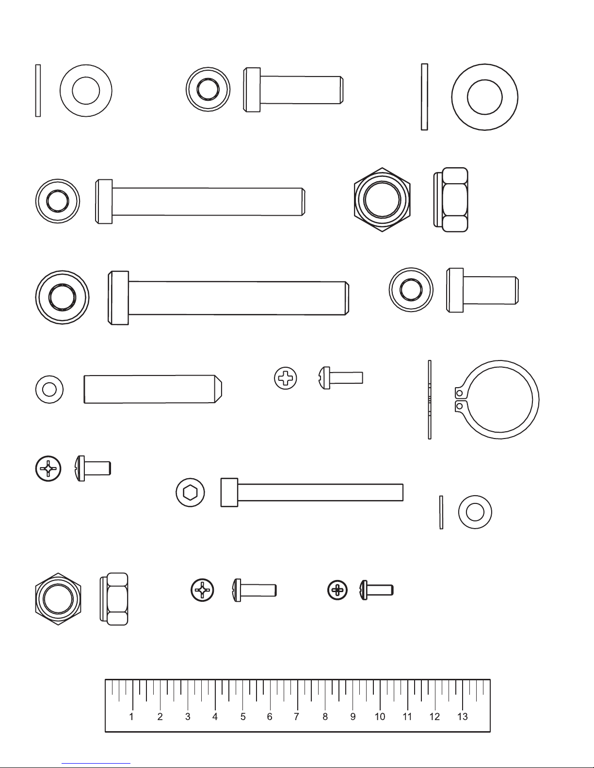
HARDWARE:
Centimeters
3/8” WASHER (#57)
M10 X 70MM SCREW (#59)
M10 X 30MM SCREW (#58)
M12 X 80MM SCREW (#60)
1/2” WASHER (#61)
M12 NYLOCK NUT (#62)
M10 X 20MM SCREW (#66)
M10 HEX TENSION SCREW (#63)
#10 x 3/4” BRONZE
PHILLIPS PAN HEAD
SCREW (#68)
M10 NYLOCK NUT (#71)
M4 LARGE HEAD ZINC
PHILLIPS PAN HEAD
SCREW (#65)
M6 x 60MM SCREW (#69)
M4 ZINC
PHILLIPS PAN HEAD
SCREW (#72)
RETAINER RING (#67)
1/4” WASHER (#70)
#6 x 3/8” BLACK
PHILLIPS PAN HEAD
SCREW (#74)
7
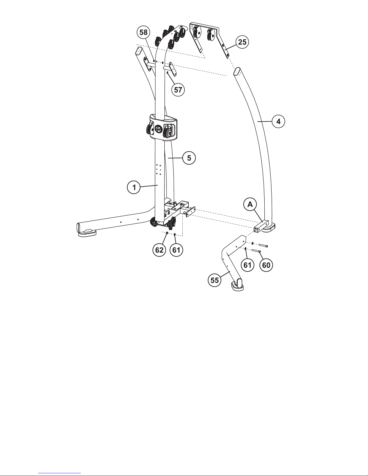
STEP 1:
Slide the RIGHT SUPPORT LEG (55) over the MOUNTING TUBE (A) of the RIGHT UPRIGHT (4). Loosely secure
the RIGHT SUPPORT LEG (55) and RIGHT UPRIGHT (4) to the FRONT UPRIGHT (1) using two M12 x 80mm
SCREWS (60), four 1/2” WASHERS (61), and two M12 HEX NYLOCK NUTS (62) as shown.
With the UPPER PULLEYASSEMBLY (25) oriented as shown, insert the UPPER PULLEYASSEMBLY (25) into the
top of the RIGHT UPRIGHT (4) and secure together the RIGHT UPRIGHT (4), FRONT UPRIGHT (1), and UPPER
PULLEY ASSEMBLY (25) using two M10 x 30mm SCREWS (58) and two FLAT 3/8” WASHERS (57).
Repeat the above steps to assemble the LEFT UPRIGHT (5) and LEFT SUPPORT LEG (56) to the FRONT
UPRIGHT (1).
NOTE: THE TOP PULLEY WELDMENT ATTACHES TO THE INSIDE OF THE UPRIGHT SIDES AND THE ORIENTATION SHOULD BE AS SHOWN.
 Loading...