

Page 1
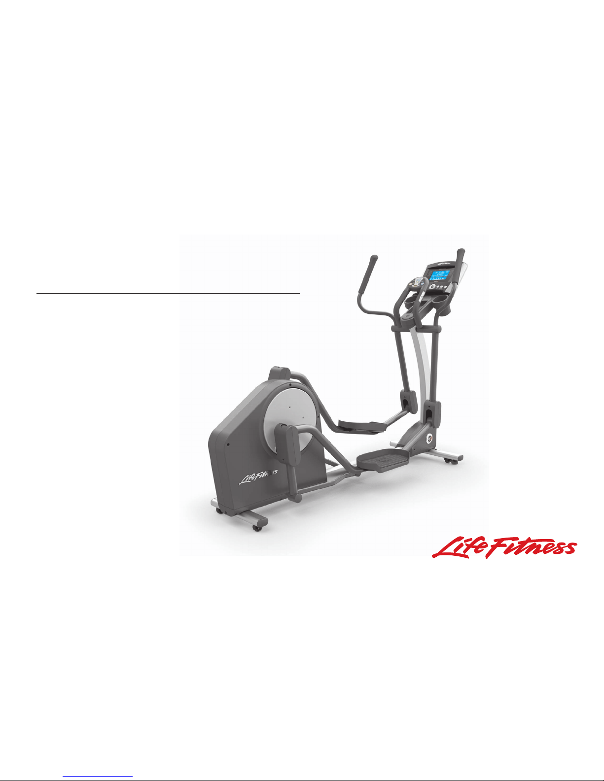
X 3 TOTAL-BODY ELLIPTICAL CROSS-TRAINER
BASE USER MANUAL
Page 2

CORPORATE H
EADQUARTERS
5100 North River Road
Schiller Park, Illinois 60176 • U.S.A.
www.lifefitness.com
INTERNATIONAL O
FFICES
8592001 Rev C-3
09/08
LIFE FITNESS ASIA PACIFIC LTD
Room 2610, Miramar Tower
132 Nathan Road
Tsimshatsui, Kowloon
HONG KONG
LIFE FITNESS ATLANTIC BV
LIFE FITNESS BENELUX
Bijdorpplein 25 - 31
2992 LB Barendrecht
THE NETHERLANDS
LIFE FITNESS DO BRAZIL
Av. Dr. Dib Sauaia Neto 1478
Alphaville, Barueri, SP
06465-140
BRAZIL
LIFE FITNESS VERTRIEBS GMBH
Dückegasse 7-9/3/36
1220 Vienna
AUSTRIA
LIFE FITNESS IBERIA
C/Frederic Mompou 5,1º 1º
08960 Sant Just Desvern (Barcelona)
SPAIN
LIFE FITNESS EUROPE GMBH
Siemensstrasse 3
85716 Unterschleissheim
GERMANY
LIFE FITNESS ITALIA S.R.L.
Via Crivellin 7/N
37010 AFFI Verona
ITALY
LIFE FITNESS LATIN
AMERICA and CARIBBEAN
5100 North River Road
Schiller Park, Illinois 60176
U.S.A.
LIFE FITNESS UK LTD
Queen Adelaide
Ely, Cambs CB7 4UB
UNITED KINGDOM
LIFE FITNESS JAPAN
Nippon Brunswick Bldg., #8F
5-27-7 Sendagaya
Shibuya-Ku, Tokyo
JAPAN 151-0051
Page 3

1.INTRODUCTION
1.1 WELCOME / SAFETY / C
AUTION
Thank you for purchasing a Life Fitness Total-Body Elliptical Cross-Trainer. Before using this product, please
read this user manual in its entirety to ensure that you have the knowledge to safely and properly operate all of
the features of your Cross-Trainer. We hope you achieve the product experience that you expect, but if you do
have any service issues, please go to the How to Obtain Product Service section which will provide information
on obtaining product service.
FCC Warning - Possible Radio / Television Interference
NOTE: This equipment has been tested and found to comply with the limits for a Class B digital device, pursuant to part
15 of the FCC rules. These limits are designed to provide reasonable protection against harmful interference in a residential installation. This equipment generates, uses and can radiate radio frequency energy, and if not installed and used
in accordance with the user manual, may cause harmful interference to radio communications. However, there is no
guarantee that the interference will not occur in a particular installation. If this equipment does cause harmful interference to radio or television reception, which can be determined by turning the equipment off and on, the user is encouraged to try to correct the interference by one or more of the following measures:
• Reorient or relocate the receiving antenna.
•
Increase the separation between the equipment and the receiver.
• Connect the equipment into an outlet on a circuit different from that to which the receiver is connected.
• Consult the dealer or an experienced radio/TV technician for help.
2
Page 4
Class HB (Home): Domestic use.
CAUTION: Any changes or modifications to this equipment could void the product warranty.
Any service, other than cleaning or user maintenance, must be performed by an authorized service representative.
There are no user-serviceable parts.
This Operation Manual describes the functions of the following products:
Life Fitness Total-Body Elliptical Cross-Trainer: X3
See Section 7, Specifications, in this manual for product-specific features.
Statement of Purpose: The Life Fitness Total-Body Elliptical Cross-Trainer is an exercise machine that combines lowimpact elliptical pedaling, where resistance is independent of speed, with push/pull arm motion to provide an efficient,
effective total body workout.
Health-related injuries may result from incorrect or excessive use of exercise equipment. The manufacturer
STRONGLY recommends seeing a physician for a complete medical exam before undertaking an exercise program, particularly if the user has a family history of high blood pressure or heart disease; or is over the age of
45; or smokes, has high cholesterol, is obese, or has not exercised regularly in the past year. The manufacturer
also recommends consulting a fitness professional on the correct use of this product.
If, at any time while exercising, the user experiences faintness, dizziness, pain, or shortness of breath, he or
she must stop immediately.
3
Page 5

1.2 TABLE OF
CONTENTS
1. Introduction . . . . . . . . . . . . . . . . . . . . . . . . . . . . . . . . . . . . . . . . . . . . . . . . . . . . . . . . . . . . . . . . . . . . . . . . . . . . .2
1.1 Welcome/Safety/Caution . . . . . . . . . . . . . . . . . . . . . . . . . . . . . . . . . . . . . . . . . . . . . . . . . . . . . . . . . . . . . .2
1.2 Table Of Contents . . . . . . . . . . . . . . . . . . . . . . . . . . . . . . . . . . . . . . . . . . . . . . . . . . . . . . . . . . . . . . . . . . .4
1.3 Important Safety Instructions . . . . . . . . . . . . . . . . . . . . . . . . . . . . . . . . . . . . . . . . . . . . . . . . . . . . . . . . . . .6
2. Assembly Instructions . . . . . . . . . . . . . . . . . . . . . . . . . . . . . . . . . . . . . . . . . . . . . . . . . . . . . . . . . . . . . . . . . . . . .9
3. Initial Setup . . . . . . . . . . . . . . . . . . . . . . . . . . . . . . . . . . . . . . . . . . . . . . . . . . . . . . . . . . . . . . . . . . . . . . . . . . . . .17
Where To Place The Total-Body Elliptical Cross-Trainer //How To Stabilize The Total-Body
Elliptical Cross-Trainer // Powering Up The Total-Body Elliptical Cross-Trainer // Mounting The Machine
4. Main Features . . . . . . . . . . . . . . . . . . . . . . . . . . . . . . . . . . . . . . . . . . . . . . . . . . . . . . . . . . . . . . . . . . . . . . . . . . .19
Contact Heart Rate // Accessories // Cushioned Pedal Insert
5. CoachZone™ . . . . . . . . . . . . . . . . . . . . . . . . . . . . . . . . . . . . . . . . . . . . . . . . . . . . . . . . . . . . . . . . . . . . . . . . . . .21
5.1 CoachZone™ Overview . . . . . . . . . . . . . . . . . . . . . . . . . . . . . . . . . . . . . . . . . . . . . . . . . . . . . . . . . . . . . . .21
5.2 CoachZone™ Descriptions . . . . . . . . . . . . . . . . . . . . . . . . . . . . . . . . . . . . . . . . . . . . . . . . . . . . . . . . . . . .23
5.3 ArmToner™ . . . . . . . . . . . . . . . . . . . . . . . . . . . . . . . . . . . . . . . . . . . . . . . . . . . . . . . . . . . . . . . . . . . . . . . .24
5.4 GluteToner™ . . . . . . . . . . . . . . . . . . . . . . . . . . . . . . . . . . . . . . . . . . . . . . . . . . . . . . . . . . . . . . . . . . . . . . .26
5.5 Timer . . . . . . . . . . . . . . . . . . . . . . . . . . . . . . . . . . . . . . . . . . . . . . . . . . . . . . . . . . . . . . . . . . . . . . . . . . . . .28
5.6 Resistance Level And Intensity Level . . . . . . . . . . . . . . . . . . . . . . . . . . . . . . . . . . . . . . . . . . . . . . . . . . . . .28
5.7 CoachZone™ Settings . . . . . . . . . . . . . . . . . . . . . . . . . . . . . . . . . . . . . . . . . . . . . . . . . . . . . . . . . . . . . . . .29
4
Page 6

6. Service & Product Maintenance . . . . . . . . . . . . . . . . . . . . . . . . . . . . . . . . . . . . . . . . . . . . . . . . . . . . . . . . . . .30
6.1 Troubleshooting . . . . . . . . . . . . . . . . . . . . . . . . . . . . . . . . . . . . . . . . . . . . . . . . . . . . . . . . . . . . . . . . . . .30
No Power // Hand Pulse Sensors Not Working Or Not Accurate // Total Body Arms Feel Loose // Noise From
Pedals // Noise With Increased Speed // Start-Up Resistance Seems Very Difficult // Can't Feel A Resistance
Change At The Beginning Levels
6.2 Preventative Maintenance Tips . . . . . . . . . . . . . . . . . . . . . . . . . . . . . . . . . . . . . . . . . . . . . . . . . . . . . . .32
The Safety Of The Total-Body Elliptical Cross-Trainer Can Be Maintained Only If The Equipment Is Examined
Regularly For Damage Or Wear. If Maintenance Is Required, Keep The Equipment Out Of Use Until
Defective Parts Are Repaired Or Replaced. Pay Special Attention To Parts That Are Subject To Wear
Outlined In The Preventative Maintenance Schedule.
6.3 How To Obtain Product Service . . . . . . . . . . . . . . . . . . . . . . . . . . . . . . . . . . . . . . . . . . . . . . . . . . . . . . .33
7. Specifications . . . . . . . . . . . . . . . . . . . . . . . . . . . . . . . . . . . . . . . . . . . . . . . . . . . . . . . . . . . . . . . . . . . . . . . . .34
8. Warranty Information . . . . . . . . . . . . . . . . . . . . . . . . . . . . . . . . . . . . . . . . . . . . . . . . . . . . . . . . . . . . . . . . . . . .35
What Is Covered // Who Is Covered // How Long Is It Covered // Who Pays Shipping And Insurance For Service //
What We Will Do To Correct Covered Defects // What Is Not Covered // What You Must Do // User Manual //
Product Registration // How To Get Parts And Service // Exclusive Warranty // Changes In Warranty
Not Authorized // Effect Of U.S. State Laws // Warranty Periods
© 2008 Life Fitness, a division of Brunswick Corporation. All rights reserved. Life Fitness is a registered trademark of Brunswick
Corporation. Any use of these trademark, without the express written consent of Life Fitness is forbidden.
5
Page 7
1.3 IMPORTANT
SAFETY INSTRUCTIONS
Read all instructions before using the Total-Body Elliptical Cross-Trainer.
SAFETY WARNING: The safety of the product can be maintained only if it is examined regularly for damage and wear. See Preventative Maintenance section for details.
• Before using this product, it is essential to read this ENTIRE operation manual and ALL instructions. The Total-Body
Elliptical Cross-Trainer is intended for use solely in the manner described in this manual.
• Always follow the console instructions for proper operation.
• Close supervision is necessary when used by or near children, invalids or disabled persons.
• Never insert objects into any opening in the Total-Body Elliptical Cross-Trainer. If an object should drop inside, carefully
retrieve it. If the item is beyond reach, contact Customer Support Services.
• Never place liquids of any type directly on the unit, except in an accessory tray. Containers with lids are recommended.
• Do not use the Total-Body Elliptical Cross-Trainer outdoors, near swimming pools or in areas of high humidity.
• Keep all loose clothing, shoelaces, and towels away from the Total-Body Elliptical Cross-Trainer pedals.
• Keep the area around the Total-Body Elliptical Cross-Trainer clear of any obstructions, including walls and furniture.
• Use caution when mounting or dismounting the Total-Body Elliptical Cross-Trainer. While exercising, always hold onto
the user arms or stationary handlebar.
• Never operate a Life Fitness product if it has been dropped, damaged, or even partially immersed in water. Contact
Life Fitness Customer Support Services.
• Keep the power cord away from heated surfaces. Do not pull the equipment by the power cord or use the power cord
as a handle.
• Do not run the power cord on the floor under or along side of the Total-Body Elliptical Cross-Trainer.
6
Page 8
• Wear shoes with rubber or high-traction soles. Do not use shoes with heels, leather soles, cleats or spikes. Do not
use the Total-Body Elliptical Cross-Trainer in bare feet.
• Do not tip the Total-Body Elliptical Cross-Trainer on its side during operation.
• Keep hands and feet away from all moving parts.
• To ensure proper functioning of this product, do not install attachments or accessories that are not provided or rec-
ommended by Life Fitness.
• Use this product in a well-ventilated area.
• Use this product on a solid, level surface.
• Make sure that all components are fastened securely.
The heart rate hand pulse sensors provide an approximate heart rate value. The sensors are not medical
devices and should not be used in any type of medical application.
SAVE THESE INSTRUCTIONS FOR FUTURE REFERENCE.
DANGER - To reduce the risk of electrical shock:
• Always unplug this appliance from the electrical outlet immediately after using and before cleaning.
SAFETY WARNING: To reduce the risk of burns, fire, electric shock, or injury to persons:
• An appliance should never be left unattended when plugged in. Unplug from outlet when not in use, and before put-
ting on or taking off parts.
• Do not operate under blanket or pillow. Excessive heating can occur and cause fire, electric shock, or injury to per-
sons.
7
Page 9

8
• Close supervision is necessary when this appliance is used by, on, or near children, invalids, or disabled persons.
• Use this appliance only for its intended use as described in this manual. Do not use attachments not recommended
by the manufacturer.
• Never operate this appliance if it has a damaged cord or plug, if it is not working properly, if it has been dropped or
damaged, or dropped into water. Return the appliance to a service center for examination and repair.
• Do not carry this appliance by supply cord or use cord as a handle.
• Keep the cord away from heated surfaces.
• Never operate the appliance with the air openings blocked. Keep the air openings free of lint, hair, and the like.
• Never drop or insert any object into any opening.
• Do not use outdoors.
• Do not operate where aerosol (spray) products are being used or where oxygen is being administered.
• To disconnect, turn all controls to the off position, then remove plug from outlet.
SAVE THESE INSTRUCTIONS FOR HOUSEHOLD USE.
Page 10
2.ASSEMBLY INSTRUCTIONS
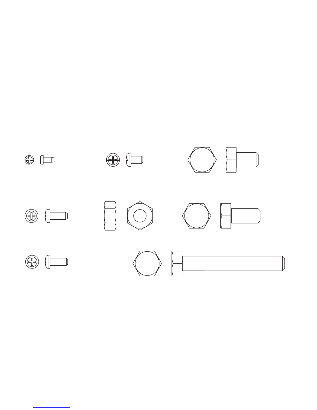
Parts List:
9
M3.5X8mmBlack Zinc
Phillips Head Screw (Qty. 6)
M5 X 12mm Black
Phillips Head Screw (Qty. 4)
M5 X 12mm Clear
Zinc Phillips Head Screw (Qty. 8)
M5 X 8mm Black
Phillips Head Screw (Qty. 4)
M10 Hex Nut (Qty. 2)
M10 X 15mm Silver Hex Head Bolt (Qty. 4)
M10 X 20mm Clear Zinc Hex Head Bolt (Qty. 3)
M10 X 70mm Silver Hex Head Bolt (Qty. 3)
Page 11
10
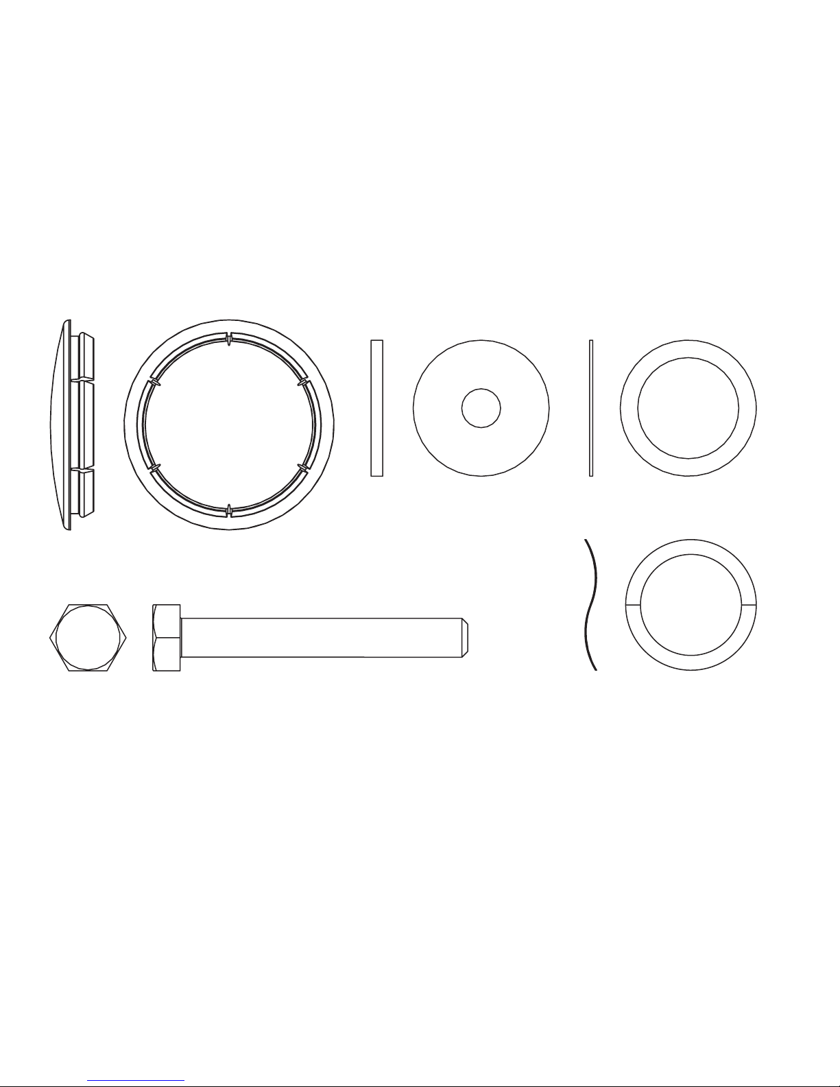
Flat W
asher 10mm ID
(Qty. 2)
Large Flat W
asher (Qty. 2)
M10 X 74mm Black Hex Head Bolt (Qty. 2)
Wave W
asher (Qty. 2)
Plastic End Cap (Qty. 2)
Page 12
Tools Needed:
17mm Socket Wrench, Phillips Screwdriver, Rubber Mallet
Step 1 Packaging
Parts: None
Remove all packaging and place main components to the side of the box. Break box down in each of the four
corners.
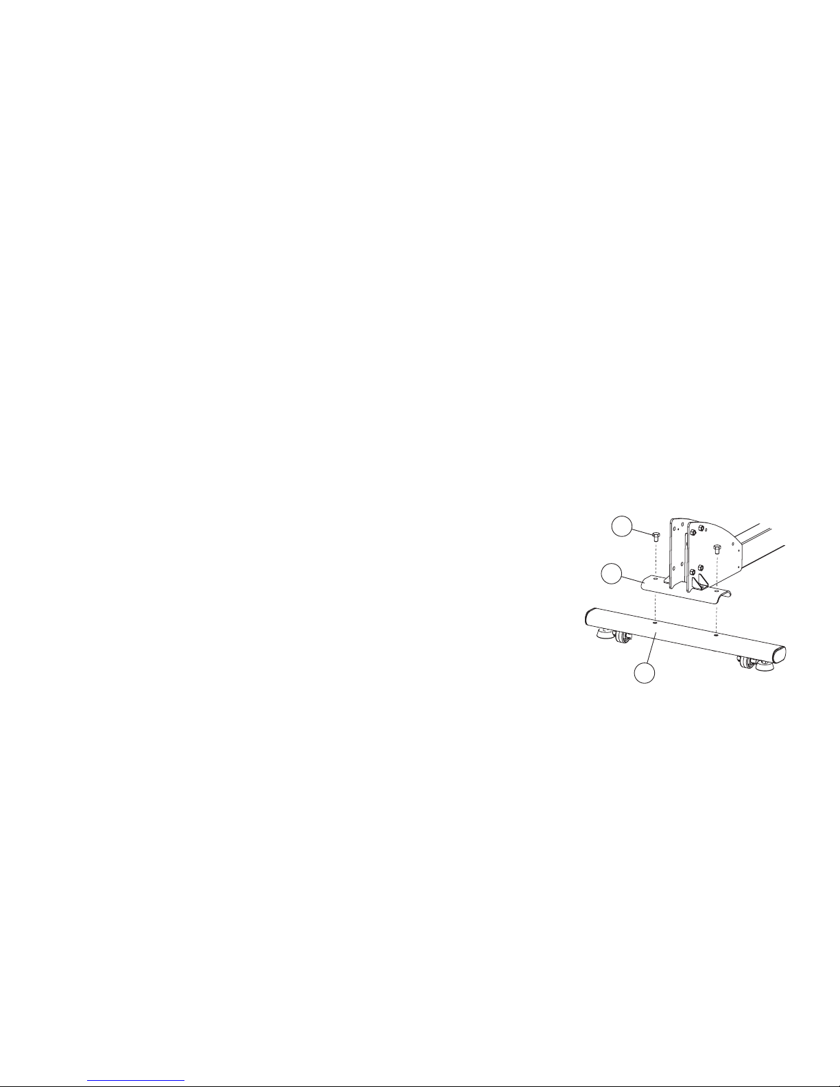
Step 2 Assemble the Stabilizer
Parts: Hardware Bag #1 (2, M10 X 15mm Silver Hex Head Bolts)
Tools: 17mm Socket Wrench
Assemble the stabilizer tube (foot) (A) to the bottom base brackets (B) of
the product using two M10 X 15mm Silver Hex Head Bolts (C).
11
C
A
B
Page 13
12
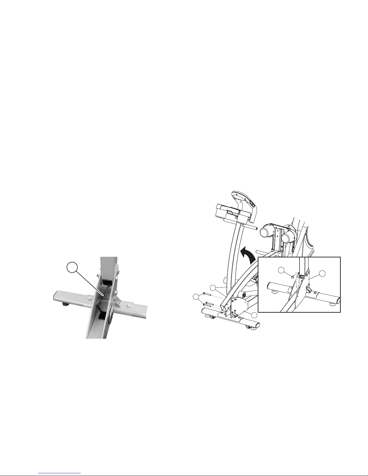
Step 3 Assemble the Console Upright
Parts: Hardware Bag #2 (3, M10 X 70mm Silver Hex Head Bolts)
(1, M10 X 20mm Clear Zinc Hex Head Bolt)
Tools: 17mm Socket Wrench
The console upright tube (D) is pre-assembled with one bolt so that you can simply lift the upright into place by
pivoting upward. Hold the upright in place and install three M10 X 70mm Silver Hex Head Bolts (E) into the
side of the main bracket (F). Install one M10 X 20mm Clear
Zinc Hex Head Bolt (G) into the front of the bracket.
CAUTION: Do not pinch wires when assembling the
upright.
Step 4 Connect Base Wiring
Parts: None
Connect the two plugs (H) at the base of the upright.
E
D
F
G
F
H
Page 14
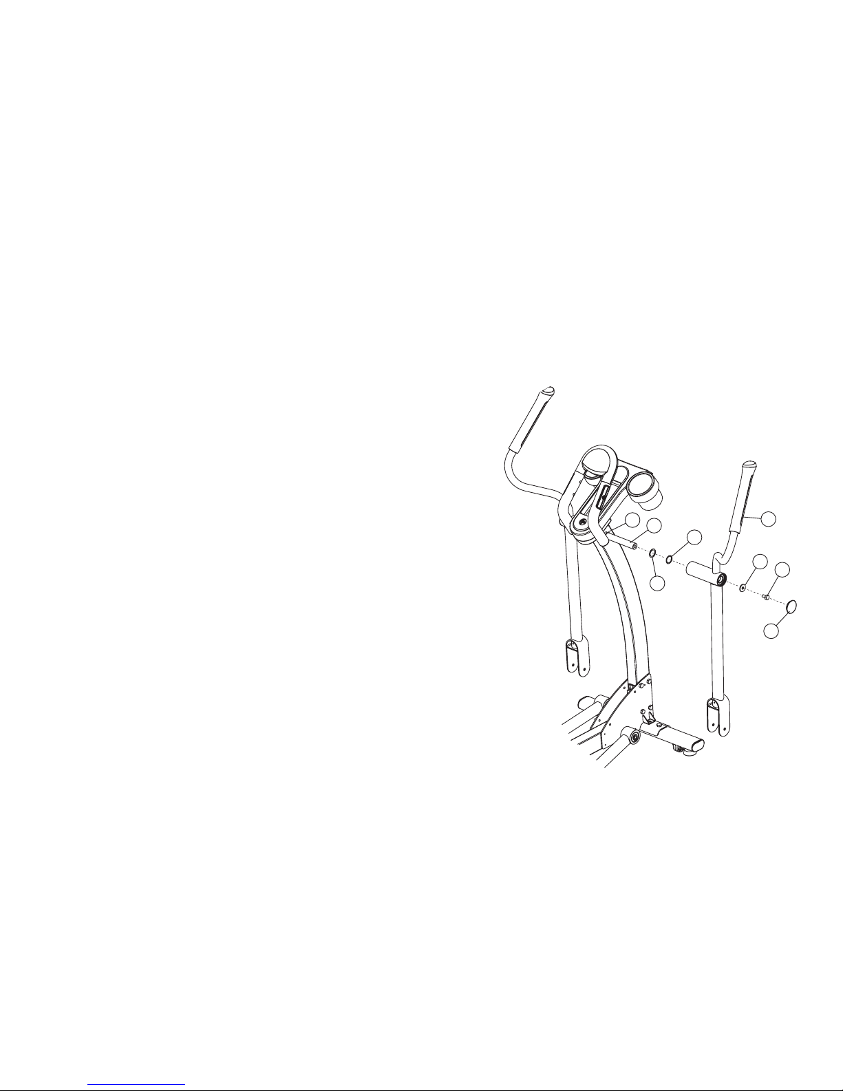
Step 5 Assemble the Rocker Arms
Parts: Hardware Bag #3 (2, Wave Washers, 2 Large Flat Washers)
(2, Flat Washers)
(2, M10 x 20mm Clear Zinc Hex Head Bolts)
(2 Plastic End Caps)
Tools: 17mm Socket Wrench, Phillips Screwdriver, Rubber
Mallet
Slide one large Flat Washer (I) and one Wave Washer (J)
onto the user right pivot shaft (K). Slide the washers fully
over the pivot shaft until seated against the pre-installed stop
ring (L).
Locate the user right rocker arm assembly (M) marked with an
“R”. With the top handgrip facing the front of the unit, slide the right
rocker arm assembly onto the user right pivot shaft until seated
against the washers.
Secure the rocker arm assembly to the pivot shaft using one Flat
Washer (N) and one M10 X 20mm Clear Zinc Hex Head Bolt (O).
Tighten the bolt securely. Repeat the procedure for the left rocker
arm assembly.
Use a rubber mallet to tap the round end of the Plastic End Caps (P)
into the side of the rocker arms.
13
N
O
P
J
L
K
I
M
Page 15
14
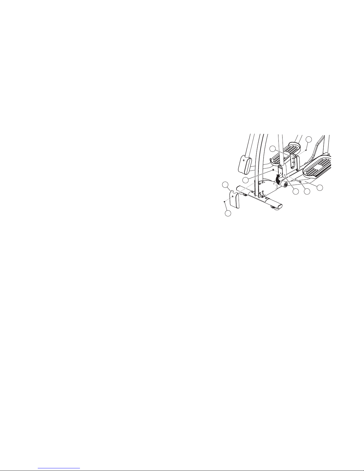
Step 6 Assemble Moving Arms to Pedal Arms; Pedal / Moving Arm
Joint Pivot Covers
Parts: Hardware Bag #4 (2, M10 X 74mm Black Hex Head Bolts)
(2, M10 Hex Nuts)
(4, M5 X 8mm Black Phillips Screws)
Tools: 17mm Socket Wrench, Phillips Screwdriver
Lift the front end of the user left pedal lever (Q) to meet the left
rocker arm clevis (R). Secure the pedal lever to the rocker arm
clevis using one M10 X 74mm Hex Head Bolt (S) and one M10
Hex Nut (T). Tighten the bolt and nut securely. Repeat the procedure for the right pedal lever and rocker arm clevis.
Attach the left side lower pivot covers (U) over the moving arm/pedal
arm pivot point. Snap the cover together over the moving arm/pedal arm pivot
point and use two M5 X 8mm Black Phillips Screws (V) to attach. Repeat for right side.
Note: Left and right covers are identical.
U
Q
R S
Y
Y
U
T
Page 16
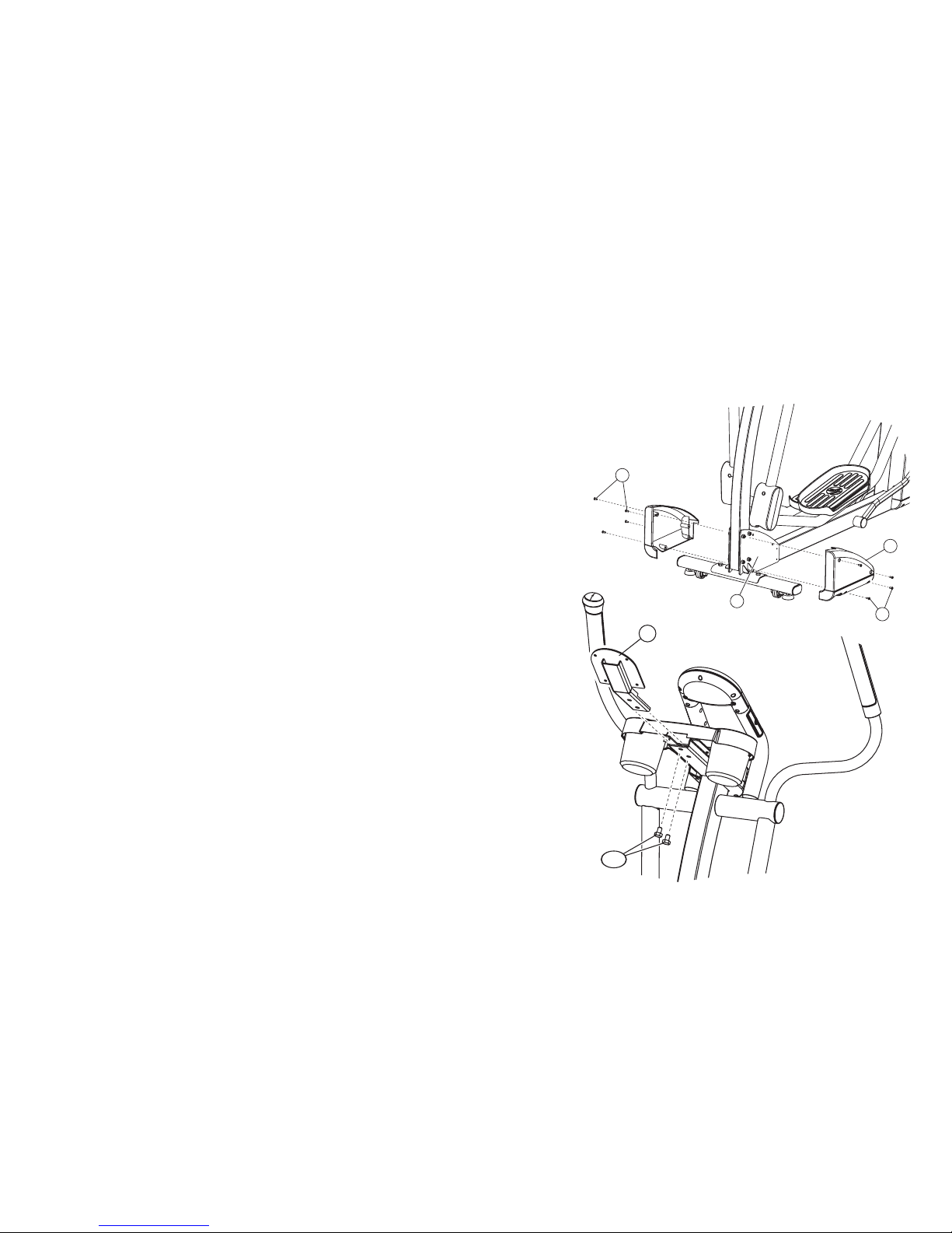
Step 7 Assemble Front Base Shroud; Console Bracket to the Upright
Parts: Hardware Bag #5 (8, M5 X 12mm Black Phillips Head Screws)
(2, M10 X 15mm Silver Hex Head Bolts)
Tools: Phillips Screwdriver, 17mm Socket Wrench
Position the left side base shroud (W) over the metal bracket (X)
and screw in with four M5 X 12mm Black Phillips Head Screws
(Y). Repeat for the right side base shroud.
Slide the console bracket (Z) into the upright. Use two M10 X
15mm Silver Hex Head Bolts (A1) to attach the console bracket
to the upright.
Note: Avoid pinching the console wires.
15
Z
A1
W
Y
Y
X
Page 17
16
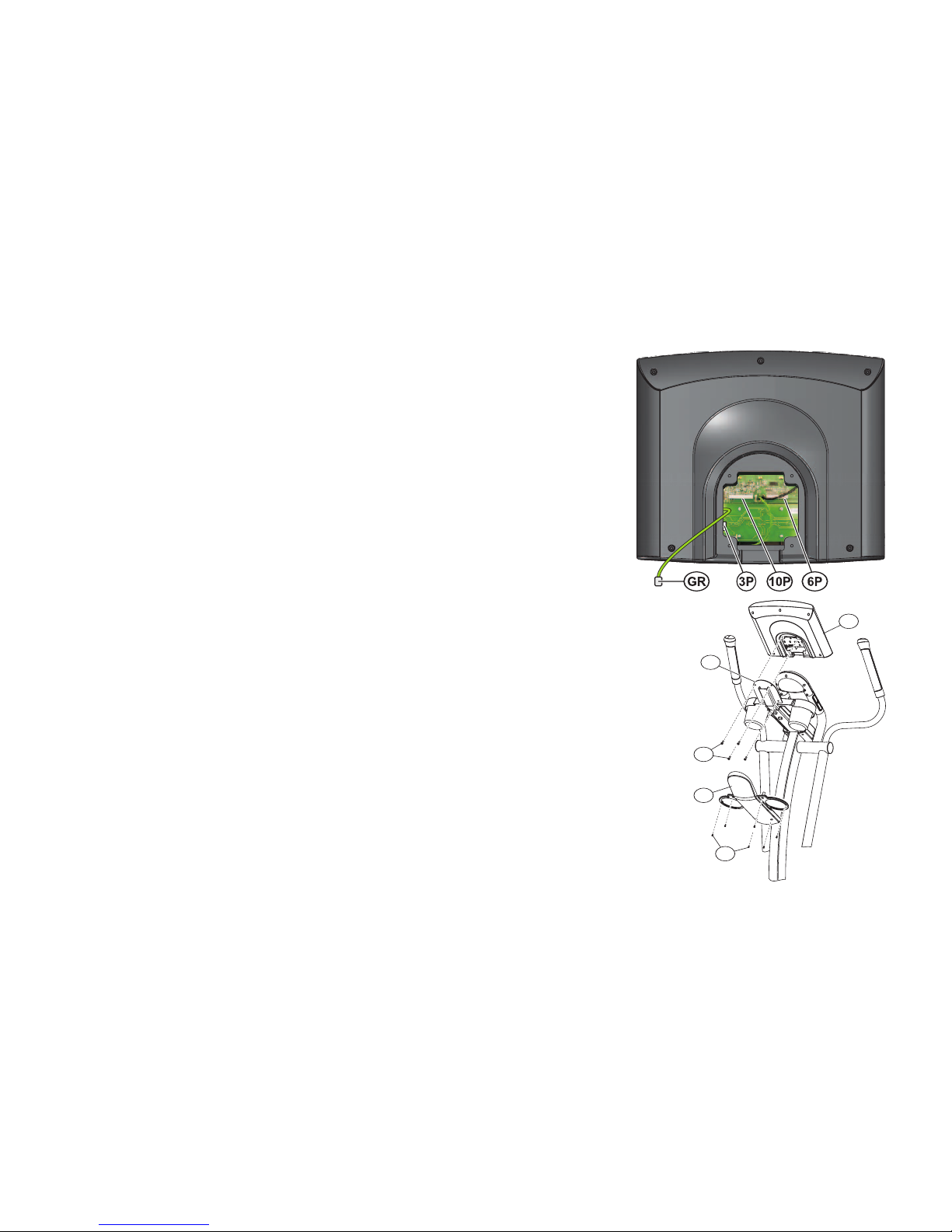
Step 8 Connect all Console Wiring; Console to Console Bracket;
Back Plastic Shell
Parts: Hardware Bag #6 (4, M5 X12mm Black Phillips Screws)
(6, M3.5 X 8mm Black Zinc Screws)
Tools: Phillips Screwdriver
Position the console (B1) close to the console bracket (C1) and follow the below
instructions to connect all wiring.
Plug cables into the back of the display console:
1. Plug the 10-pin connector at the end of the upper wire harness into the 10-
pin connector (10P) in the back of the display console. Make sure the connector snaps into place.
2. Plug the 3-pin connector at the end of the heart rate cable into the 3-pin con-
nector (3P) in the back of the display console. Make sure the connector
snaps into place.
3. Plug in the flat 6-pin (6P) connector for the CoachZone.
4. Push excess cable(s) into the opening of the upright tube assembly.
5. Plug the spade connector attached to the console plate into the connector (GR) lead-
ing from the back of the display console.
Line up the four holes in the console bracket with the four holes in the back of the display
console. Attach the display console using four M5 X 12mm Black Phillips Screws (D1). Be
careful not to pinch cables between the console and the console bracket. Be sure to get
each screw started before fully tightening.
Note: To avoid stripping, do not overtighten the screws.
Attach the plastic shell (E1) that covers the steel bracket in the back of the console using
six M3.5 X 8mm Black Zinc Screws (F1).
Step 9 Plug In the Unit
Parts: Electric Cord
Plug the black cord into the back of the machine and into a household electrical outlet.
E1
F1
D1
B1
C1
Page 18
17
3.INITIAL SETUP
Read the entire User Manual before setting up the Total-Body Elliptical Cross-Trainer.
WHERE TO PLACE THE
TOTAL-BODY ELLIPTICAL CROSS-TRAINER
After following all safety instructions move the Total-Body Elliptical Cross-Trainer to the
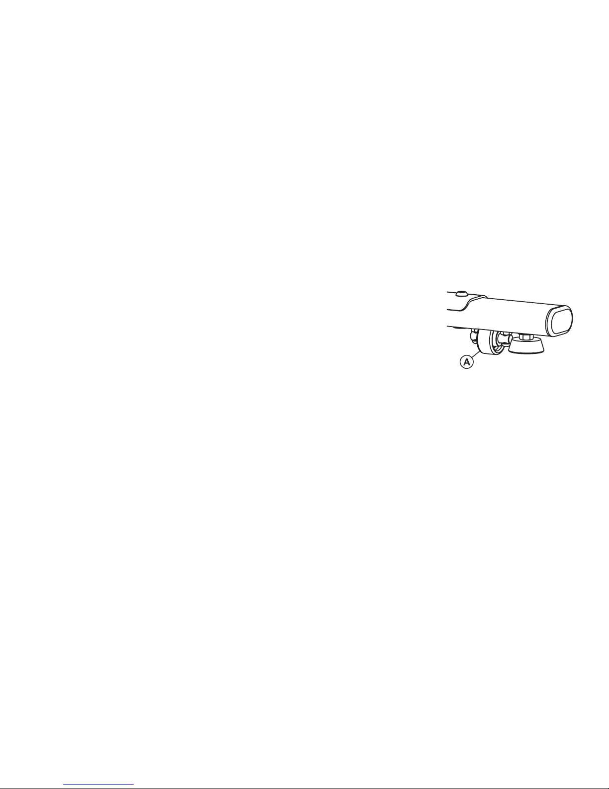
place where it will be used. See specifications for full dimensions if needed. The TotalBody Elliptical Cross-Trainer is equipped with front and rear wheels so that it is simple to
push or pull the Total-Body Elliptical Cross-Trainer to its final destination. To use the
wheels make sure that the levelers are twisted up far enough so that all wheels (A) can
engage with the floor. Once the Total-Body Elliptical Cross-Trainer is properly positioned,
allow enough space in the front of the Total-Body Elliptical Cross-Trainer for the movement of the pedal levers. Also be sure to allow space on the side so that it is easy to
mount the Total-Body Elliptical Cross-Trainer from the side.
CAUTION: Make certain you have plenty of room for the swing of the moving arms.
CAUTION: Place the Total-Body Elliptical Cross-Trainer in a dry place. Do not place in highly humid areas, like near
swimming pools, as rust and corrosion may occur.
HOW TO STABILIZE THE TOTAL-BODY ELLIPTICAL CROSS-TRAINER
Once the cross-trainer is positioned in the room lower the levelers on the front stabilizer to contact the floor. The levelers
will keep the Total-Body Elliptical Cross-Trainer fixed to the floor while using it.
CAUTION: Do not use the Total-Body Elliptical Cross-Trainer without the levelers touching the floor.
After placing the Total-Body Elliptical Cross-Trainer where it will be used, check the stability. If there is even a slight rock-
ing motion, or the unit is not stable the levelers will need to be adjusted. Determine which leveler is not resting firmly on
the floor. To adjust the levelers downward twist the rubber portion of the leg counterclockwise. To adjust the levelers
upward twist the rubber portion of the leg clockwise.
Page 19
18
POWERING UP THE TOTAL-BODY ELLIPTICAL CROSS-TRAINER
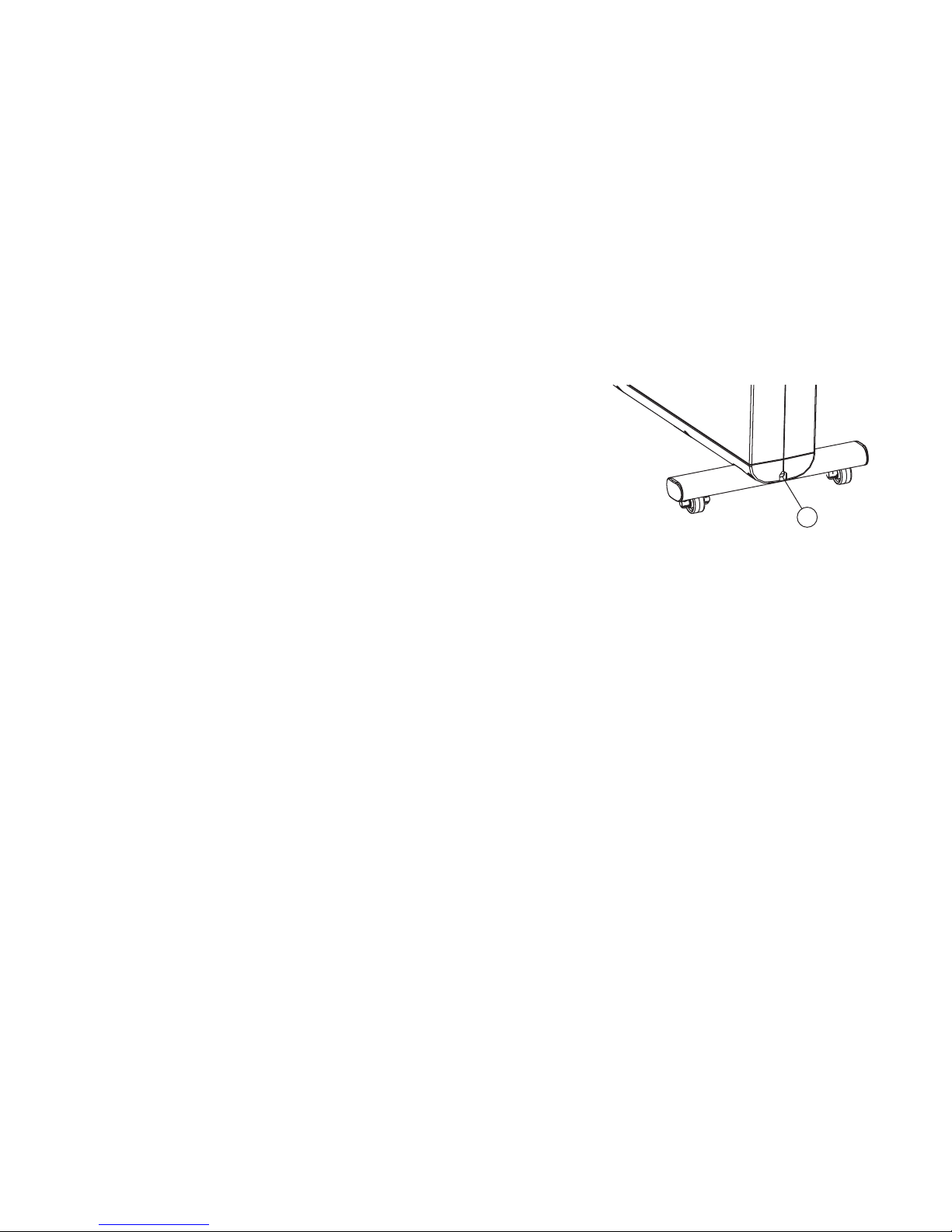
Your Life Fitness Total-Body Elliptical Cross-Trainer may come with either a U.S.
power supply or one of several international power supplies. Insert the appropriate power adapter jack into the connector (B) on the back of the Total-Body
Elliptical Cross-Trainer. Then insert the plug into the wall outlet. Make sure the
cord is placed so it doesn't bind and will not be walked on. Then check that the
main LCD display lights up, and press a button on the CoachZone to make sure
it is powered. If not, recheck the plug and the wall connections and make sure
the wall outlet has power.
MOUNTING THE MACHINE
When mounting the machine it is recommended that the pedal closest to you is in its lowest position. This can be done by
pushing the arms to rotate the pedal until it is centered to the side of you at its lowest position. If you are standing to the left
side of the machine, when facing the console, place your left foot on the pedal closest to you and then swing your right leg
over to the right pedal. Use the stationary handlebar to stabilize yourself.
B
Page 20

19
4.MAIN FEATURES
CONT ACT HEART RATE
The X3 includes hand pulse sensors on the stationary handlebar that are a built-in heart rate monitoring system. During a
workout grasp the hand pulse sensors to monitor your heart rate. If your console comes equipped with a heart rate chest
strap we recommend using it during workouts and using the hand pulse sensors to only occasionally monitor your heart
rate when not using the chest strap. In addition, to utilize heart rate controlled workouts the chest strap must be used. For
the most accurate reading, use a comfortable grip. The console will show a heart rate reading after 15 to 20 seconds.
Hand pulse sensors can work differently with different body types. With some individuals it can be very difficult to extract a
heart rate reading. Follow the tips below to improve the heart rate reading:
· Remove your hands from the heart rate sensors and wait for the heart rate display to clear. Grasp sensors again.
· Make sure hands are fully contacting the sensors.
· Dry hands periodically during use.
· Limit movement.
· Clean hand pulse sensors.
Note: The heart rate hand pulse sensors provide an approximate heart rate value. The sensors are not medical devices
and should not be used in any type of medical application.
Page 21
ACCESSORIES
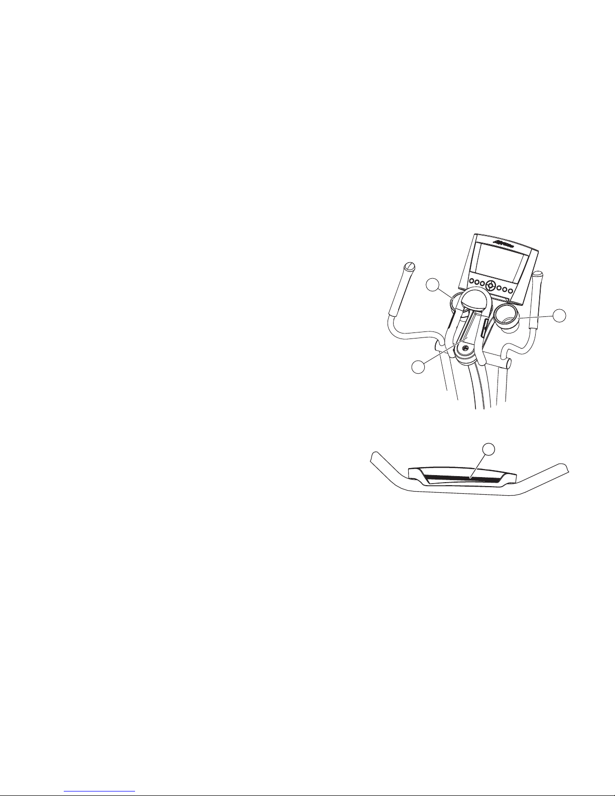
The X3 comes standard with two water bottle holders (C) and an accessory tray (D).
CUSHIONED PEDAL INSERT
The X3 comes equipped with a cushioned pedal insert (E) for increased
comfort during workouts.
20
C
C
D
E
Page 22

21
5.COACHZONE™
5.1 COACHZONE
™ OVERVIEW
The CoachZone is designed to provide extra workout variety and motivation through additional instruction and feedback.
The ArmToner and GluteToner workout enhancements help users target specific muscle groups and break the workout
into manageable increments. The appropriate muscle groups that you should be using will illuminate when you perform
specific movements. The UP/DOWN level arrow keys are a convenient way for users to change difficulty levels.
USING THE COACHZONE™
• Select a workout from the main console display.
• Begin workout.
• At any point during a workout, choose a CoachZone workout enhancement: ArmToner or GluteToner.
• Follow the coaching instructions displayed on the LED.
Page 23
22
A
A
F
C
E
E
D
D
B
B
Page 24

5.2 COACHZ
ONE™ DESCRIPTIONS
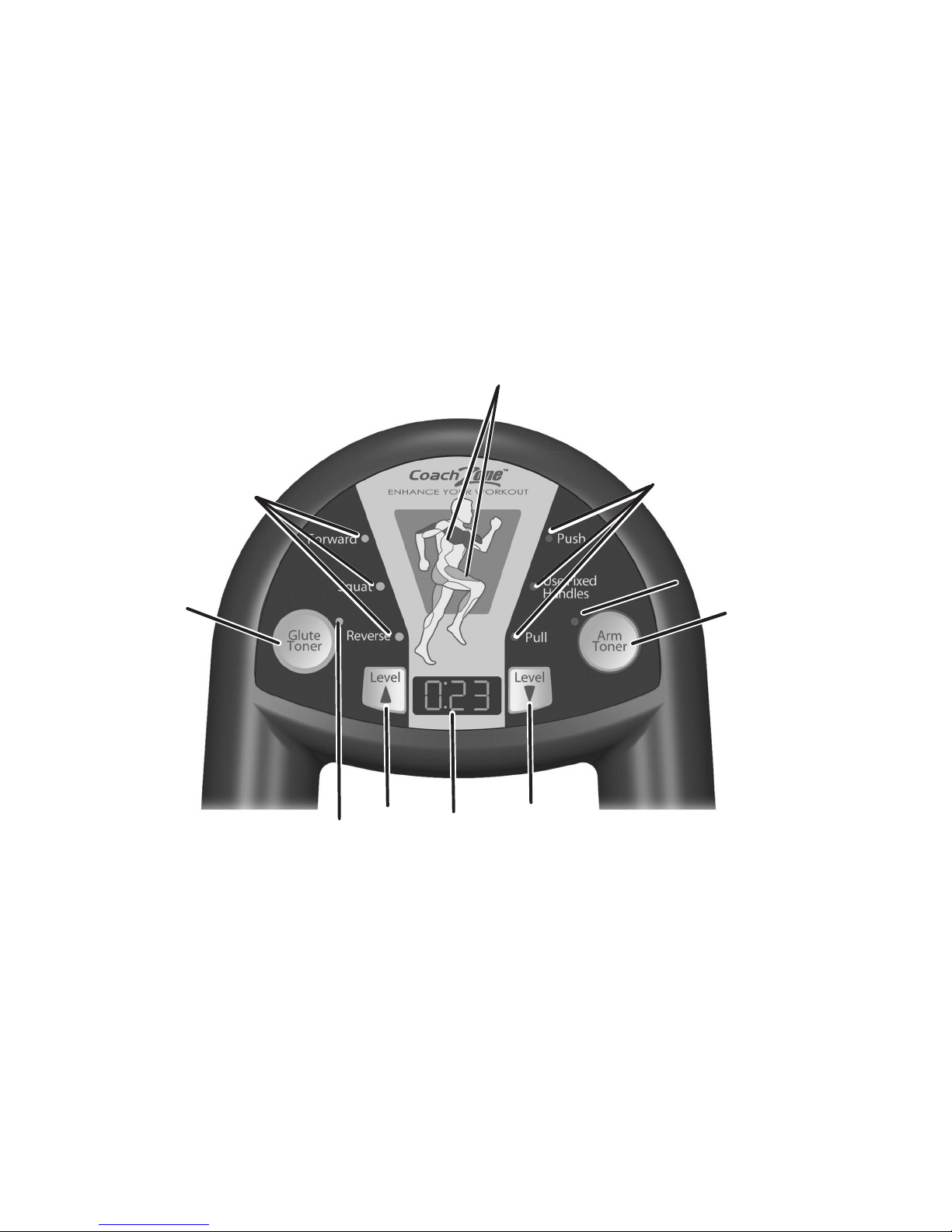
This section lists and describes the functions for the keys and LEDs on the CoachZone.
A. WORKOUT ENHANCEMENT SELECTON KEYS:
Select the ArmToner or GluteToner to concentrate on specific upper body or lower body muscles.
B. SELECTION INDICATOR LEDs:
A light next to the selected workout enhancement will illuminate.
C. MUSCLE INDICATOR LEDs:
The Muscle Indicator LEDs show you which muscles should be utilized while performing specific movements. The
bicep, chest, tricep, quad, calf, hamstring, and/or glutes will illuminate depending on your selection.
D. COACH INDICATOR LEDs:
The Coach Indicator LEDs prompt you to focus on one or more of the following movements: forward, squat, reverse,
push, use fixed handles, or pull.
E. UP/DOWN LEVEL KEYS:
Press the UP/DOWN Level Arrow Keys to increase or decrease either the resistance or difficulty level.
F. TIMER
The amber LED timer displays a count down of time remaining for workout intervals (ranging from 15-60 seconds).
Note: The CoachZone timer acts independently of the console timer.
23
Page 25

5.3 ARMT
ONER™
The ArmToner selection utilizes a pre-programmed series of prompts and intervals focused on upper-body muscles.
ACTIV ATE A
RMTONER
Press the ArmToner key during any workout to activate the selection.
PAUSE ARMTONER
Press the ArmToner key once while using the ArmToner selection. PAU will display on the CoachZone Timer. Press the
ArmToner key again to resume. The CoachZone automatically shuts off if the ArmToner key isn’t pressed within 5 minutes.
STOP ARMTONER
Press and hold the ArmToner key while using the ArmToner selection. The timer and coaching will cease. The CoachZone
automatically shuts down after 5 minutes of non-use.
DISPLAY CHANGES
The following blue coach indicator LEDs will activate and prompt you to focus on certain upper body movements: push,
pull, and use fixed handles. The corresponding blue muscle indicator LEDs will illuminate to display the muscles utilized.
See the ArmToner Coach and Muscle Indicator Chart on the next page for additional information.
24
Page 26
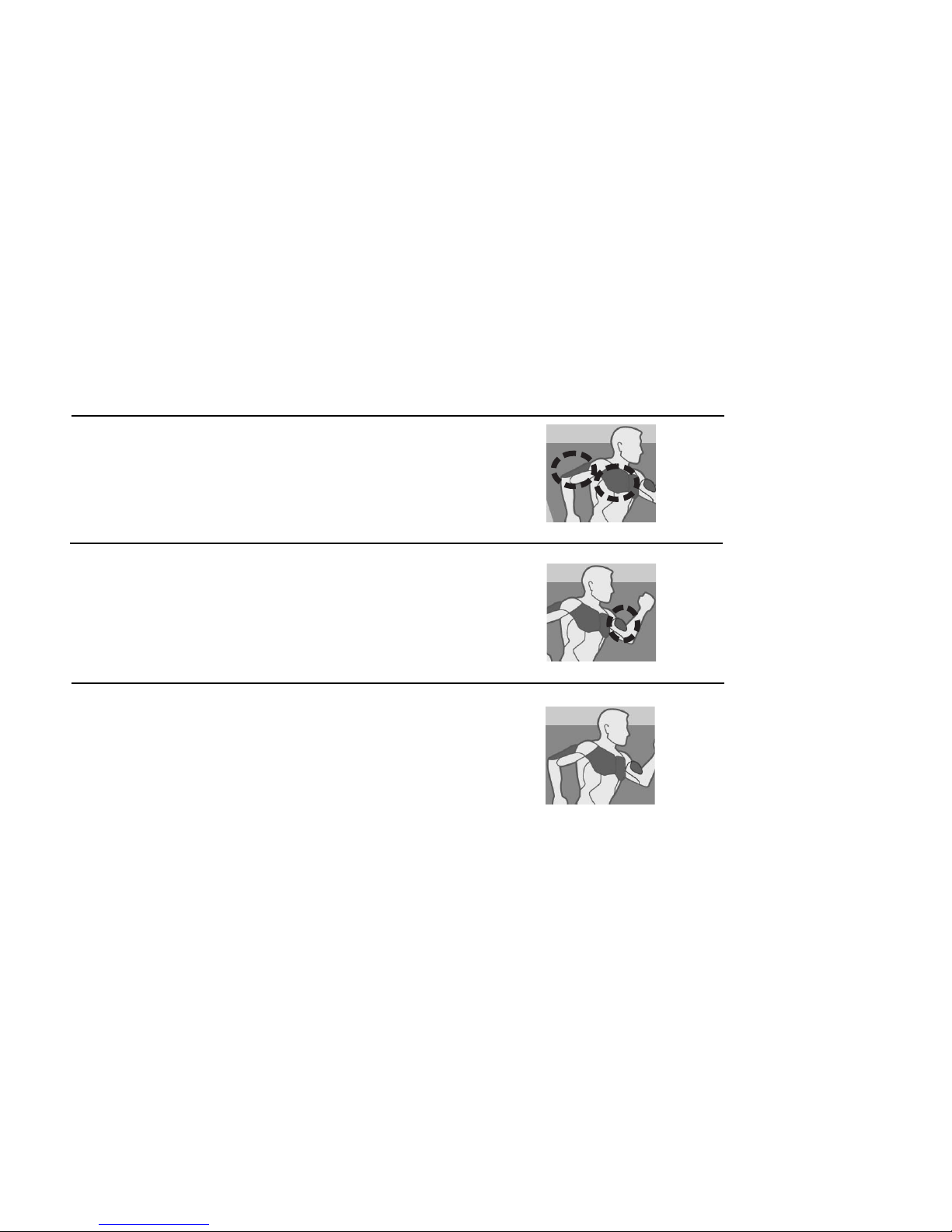
ArmT oner™ Coach and Muscle Indicator Chart
Coach Indicator Muscle Indicator
Push Chest; Tricep
Pull Bicep
Use Fixed Handles Upper body gets a rest
Note: Upper body motions will always work in conjunction with lower body movements.
25
Page 27

5.4 GLUTET
ONER™
The GluteToner selection utilizes a pre-programmed series of prompts and intervals focused on lower body muscles and
glutes.
ACTIV ATE
GLUTETONER
Press the GluteToner key during any workout to activate the selection.
PAUSE GLUTETONER
Press the GluteToner key once while using the GluteToner selection. PAU will display on the CoachZone Timer. Press the
GluteToner key again to resume.
STOP GLUTETONER
Press and hold the GluteToner key while using the GluteToner selection. The timer and coaching will cease. The
CoachZone automatically shuts down after 5 minutes of non-use.
DISPLAY CHANGES
The following amber coach indicator LEDs will activate and prompt you to focus on certain lower body movements: forward,
reverse, and squat. The corresponding amber muscle indicator LEDs will illuminate to display the muscles utilized. See the
GluteToner Coach and Muscle Indicator Chart on the next page for additional information.
26
Page 28
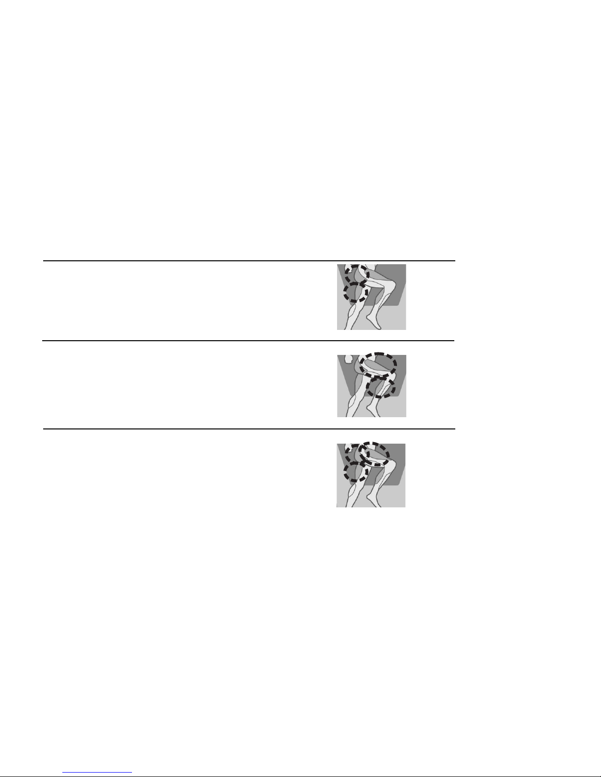
GluteT oner™ Coach and Muscle Indicator Chart
Coach Indicator Muscle Indicator
Forward Hamstring; Glute
Reverse Quad; Calf
Squat Glute; Quad; Hamstring
Note: The squat motion should only be done while pedaling in reverse and holding the fixed or stationary handles.
27
Page 29

5.5 TIMER
The amber LED timer breaks workouts into manageable increments by displaying a count down of the time remaining on
specific movements. When the timer reaches zero, the Coach LEDs will change. Slow your movement to a complete
stop, and begin the next interval.
5.6 RESISTANCE L
EVEL &INTENSITY LEVEL
KEY PRESS
The Resistance Level UP/DOWN Arrow Keys only function after a user selects and begins a workout using the X3 main
console. The UP/DOWN Level Arrow Keys control the brake resistance level (1-20) during a Quick Start or Manual workout.
The UP/DOWN Level Arrow Keys control the overall difficulty level (1-20 with corresponding ranges) during the following
workouts: Random, Hill, EZ Incline, and Sports Training.
MAIN CONSOLE DISPLAY CHANGES
The digital reading for the actual resistance or difficulty level changes on the main console display when a user presses the
UP/DOWN Level Arrow Keys on the CoachZone.
28
Page 30

5.7 COACHZ
ONE™ SETTINGS
The CoachZone allows the user to change certain settings.
AUDIO ADJUSTMENT INSTRUCTIONS
A beeping sound occurs whenever the timer reaches zero or a new program is selected. The user can turn off the beeping sound by pressing and holding the GluteToner key for seven seconds. A beep will sound to confirm the change in
settings.
Note: Settings can only be changed when the CoachZone is idle. They cannot be changed while using a workout
enhancement.
ATTRACT DISPLAY
The user can choose to have an attract screen shown in place of the default dark sleep display. It will repeatedly show a
sequence of lights and a countdown from 5 to 0. The attract screen setting can be enabled or disabled by pressing and
holding the GluteToner and ArmToner keys simultaneously for five seconds. The Coach LEDs will flash to confirm the
change in setting.
Note: Settings can only be changed when the CoachZone is idle. They cannot be changed while using a workout
enhancement.
29
Page 31

6.SERVICE &PRODUCT MAINTENANCE
6.1 TROUBLESHOOTING
NO POWER
Check to see that the power cord is fully plugged into the back of the Total-Body Elliptical Cross-Trainer and into the wall.
Make sure the power cord is fully seated into the back of the Total-Body Elliptical Cross-Trainer.
HAND P
ULSE SENSORS NOT WORKING OR NOT ACCURATE
Hand pulse sensors can work differently with different body types. With some individuals it can be very difficult to extract a
heart rate reading. Follow the tips below to improve the heart rate reading:
• Remove your hands from the heart rate sensors and wait for the heart rate display to clear. Grasp sensors again.
• Make sure hands are fully contacting the sensors.
• Dry hands periodically during use.
• Limit movement.
• Clean hand pulse sensors.
• May need to wait longer for heart rate to display.
Note: The heart rate hand pulse sensors provide an approximate heart rate value. The sensors are not medical devices and
should not be used in any type of medical application.
Warning: Chest strap heart rate reading overrides contact heart rate.
30
Page 32

TOTAL BODY ARMS FEEL LOOSE
Remove the moving arm pivot covers and check to make certain the bolt holding the total body arms in place is fully
tightened. If the total body arms still feel loose, you may need to disassemble the total body arms and make sure all of
the proper hardware from the assembly instructions was used.
NOISE FROM PEDALS
Some noise from the pedals is normal. It will vary depending on the weight of the user. Check accessible hardware
beneath pedal to make certain it is tight.
NOISE WITH INCREASED SPEED
It is normal for any mechanical device to become louder as speed increases.
START-UP RESISTANCE SEEMS VERY DIFFICULT
Turn the unit off and then on again.
CAN'
T FEEL A RESISTANCE
CHANGE AT THE BEGINNING LEVELS
The resistance curve of the Total-Body Elliptical Cross-Trainer is designed so that you can feel a greater difference in
resistance at higher levels.
31
Page 33

32
6.2 PREVENTATIVE
MAINTENANCE TIPS
The safety of the Total-Body Elliptical Cross-Trainer can be maintained only if the equipment is examined regularly for
damage or wear. If maintenance is required, keep the equipment out of use until defective parts are repaired or
replaced. Pay special attention to parts that are subject to wear outlined in the Preventative Maintenance Schedule.
The following preventative maintenance tips will keep the Total-Body Elliptical Cross-Trainer operating at peak performance.
• Locate the Total-Body Elliptical Cross-Trainer in a cool, dry place.
• Clean the top surface of the pedals when needed.
• Use a 100% cotton cloth, lightly moistened with water or a mild liquid cleaning product, to clean the product.
Other fabrics, including paper towels, may scratch the surface of the product. Do not use ammonia or acidbased cleaners. At no time should cleaner be applied directly to the machine.
• Long fingernails may damage or scratch the surface of the console or CoachZone; use the pad of the finger to
press the keys.
Page 34

6.3 HOW TO
OBTAIN P
RODUCT SERVICE
1. Verify the symptom and review the operating instructions. The problem may be unfamiliarity with the product and its features and workouts.
2. Locate and document the serial number of the unit. The serial number plate is located on the rear stabilizer, below the
shroud.
3. Contact Customer Support Services via the Web at: www.lifefitness.com, or call the nearest Customer Support Services
group:
For Product Service within
the United States and Canada:
Telephone: (+1) 847.451.0036
FAX: (+1) 847.288.3702
Toll-free telephone: 800.351.3737
33
For Product Service
Internationally:
Life Fitness Europe GmbH
Telephone: (+49) 089.317.751.66
FAX: (+49) 089.317.751.38
Life Fitness (UK) LTD
Telephone: (+44) 1353.665507
FAX: (+44) 1353.666018
Life Fitness Atlantic BV
Life Fitness Benelux
Telephone: +31 (0) 180 64 66 66
FAX: +31 (0) 180 64 66 99
Life Fitness Italia S.R.L.
Telephone: (+39) 0457.237.811
FAX: (+39) 0457.238.197
Toll-free telephone: 800.438836
Life Fitness Vertriebs GmbH
Telephone: (+43) 1615.7198
FAX: (+43) 1615.7198.20
Life Fitness Asia Pacific Ltd
Telephone: (+852) 2891.6677
FAX: (+852) 2575.6001
Life Fitness Latin America
and Caribbean
Telephone: (+1) 847.288.3964
FAX: (+1) 847 288.3886
Life Fitness Brazil
Telephone: (+55) 11.7295.2217
FAX: (+55) 11.7295.2218
Life Fitness Japan
Telephone: (+81) 3.3359.4306
FAX: (+81) 3.3359.4307
Life Fitness Iberia
Telephone : (+34) 93 672 4660
FAX : (+34) 93 672 4670
Page 35

34
7.SPECIFICATIONS
Designed Use: Home
Max User Weight: 350 lbs / 159 kilograms
Resistance System: Eddy Current
Stride Length: 20 inches
CoachZone
™:Yes
Contact Heart Rate: Yes
Cushioned Pedal Insert: Yes
Accessories: 2 water bottle holders and 1 accessory tray
Power Supply: 120 Volt (U.S.), 220 Volt (Europe), 240+ Volt (Australia)
ASSEMBLED / WORKING DIMENSIONS
Length 81 inches / 206 centimeters
Width 30 inches / 76 centimeters
Height 59 inches / 150 centimeters
Weight 225 pounds / 102 kilograms
SHIPPING DIMENSIONS:
Length 81 inches / 206 centimeters
Width 21 inches / 53 centimeters
Height 32 inches / 81 centimeters
Weight 242 pounds / 110 kilograms
Page 36

35
8. WARRANTY INFORMATION
WHAT IS COVERED:
This Life Fitness consumer product ("Product") is warranted to be free of all defects in material and workmanship.
WHO IS COVERED:
The original purchaser or any person receiving a newly purchased Product as a gift from the original purchaser.
HOW LONG IS IT COVERED:
Residential: All electrical and mechanical components and labor are covered, after the date of purchase, as listed on the chart at the
end of this section.
Non-Residential: Warranty void (this Product is intended for residential use only).
WHO PAYS SHIPPING & INSURANCE FOR SERVICE:
If the Product or any warranted part must be returned to a service facility for repairs, Life Fitness will pay all shipping and insurance
charges during the warranty period (within the United States only). The purchaser is responsible for shipping and insurance charges
after the warranty has expired.
WHAT WE WILL DO TO CORRECT COVERED DEFECTS:
We will ship to you any new or rebuilt replacement part or component, or, at our option, replace the Product. Such replacement parts
are warranted for the remaining portion of the original warranty period.
WHAT IS NOT COVERED:
Any failures or damage caused by unauthorized service, misuse, accident, negligence, improper assembly or installation, debris
resulting from any construction activities in the Product's environment, rust or corrosion as a result of the Product's location, alterations or modifications without our written authorization or by failure on your part to use, operate and maintain the Product as set out
in your User Manual ("Manual"). All terms of this warranty are void if this Product is moved beyond the continental borders of the
United States of America (excluding Alaska, Hawaii and Canada) and are then subject to the terms provided by that country's local
authorized Life Fitness Representative.
Page 37

WHAT YOU MUST DO:
Retain proof of purchase (our receipt of the attached registration card assures registration of purchase information but is not required);
use, operate and maintain the Product as specified in the Manual; notify Customer Service of any defect within 10 days after discovery of the defect; if instructed, return any defective part for replacement or, if necessary, the entire Product for repair. Life Fitness
reserves the right to decide whether or not a product is to be returned for repair.
USER MANUAL:
It is VERY IMPORTANT THAT YOU READ THE MANUAL before operating the Product. Remember to perform the periodic maintenance requirements specified in the Manual to assure proper operation and your continued satisfaction.
PRODUCT REGISTRATION:
Register online at www.lifefitness.com/registration. Our receipt assures that your name, address and date of purchase are on file as a
registered owner of the Product. Failure to return the card will not affect your rights under this warranty. Being a registered owner assures
coverage in the event you lose your proof of purchase. Please retain your proof of purchase, such as your bill of sale or receipt.
HOW TO GET PARTS & SERVICE:
Simply call Customer Service at 1-800-351-3737 or (+1) 847-288-3300, Monday through Friday from 8:00 a.m. to 5:00 p.m. Central
Standard Time, and tell them your name, address and the serial number of your Product (consoles and frames may have separate
serial numbers). They will tell you how to get a replacement part, or, if necessary, arrange for service where your Product is located.
EXCLUSIVE WARRANTY:
THIS LIMITED WARRANTY IS IN LIEU OF ALL OTHER WARRANTIES OF ANY KIND EITHER EXPRESSED OR IMPLIED,
INCLUDING BUT NOT LIMITED TO THE IMPLIED WARRANTIES OF MERCHANTABILITY AND FITNESS FOR A PARTICULAR
PURPOSE, AND ALL OTHER OBLIGATIONS OR LIABILITIES ON OUR PART. We neither assume nor authorize any person to
assure for us any other obligation or liability concerning the sale of this Product. Under no circumstances shall we be liable under this
warranty, or otherwise, of any damage to any person or property, including any lost profits or lost savings, for any special, indirect,
secondary, incidental or consequential damages of any nature arising out of the use of or inability to use this Product. Some states do
not allow the exclusion or limitation of implied warranties or of liability for incidental or consequential damages, so the above limitations or exclusions may not apply to you. Warranties may vary outside the U.S. Contact Life Fitness for details.
36
Page 38
37
CHANGES IN WARRANTY NOT AUTHORIZED:
No one is authorized to change, modify or extend the terms of this limited warranty.
EFFECT OF U.S. STATE LAWS:
This warranty gives you specific legal rights and you may have other rights which vary from state to state.
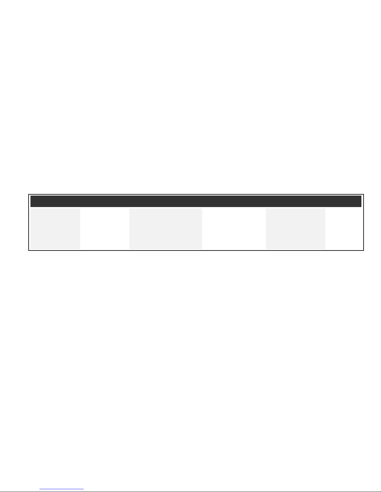
WARRANTY PERIODS:MODEL LIFETIME 7 YEARS 5 YEARS 3 YEARS 1 YEAR
MODEL LIFETIME 3 YEARS 2 YEARS 1 YEAR 6 MONTHS
X3 Frame Electrical Parts & Console Labor Cushioned
Mechanical Parts (All LCD displays & Pedal
(Base Unit) circuit boards) Insert
Note: Warranties outside the U.S. may vary.
Page 39

5100 N. RIVER ROAD, SCHILLER PARK, ILLINOIS 60176
LIFEFITNESS.COM
Life Fitness offers a full line of premier fitness equipment for the home.
TOTAL-BODY ELLIPTICAL CROSS-TRAINERS | TREADMILLS | LIFECYCLE®EXERCISE BIKES | GYM SYSTEMS
©2006 Life Fitness, a division of Brunswick Corporation. All rights reserved. Life Fitness is a registered trademark of Brunswick Corporation. 8592001 Rev C-3 (09.08)
 Loading...