

Lifecanvas Technologies SMARTLABEL Quick Installation Manual
SMARTLABEL
SCREW BEARING
Quick Installation Guide
Carefully remove SmartLabel, the SmartBox, and the SmartBox+ from the packaging and place
1
at the installation location. We recommend at least 8 inches of space around the devices for
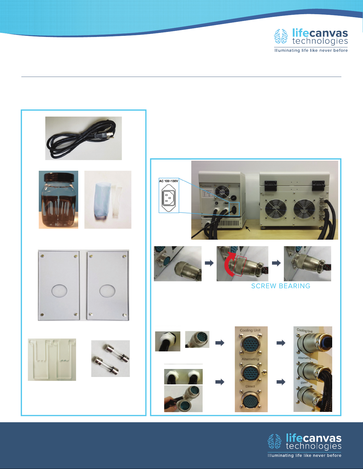
proper airfl ow, and a level surface. Locate the parts listed below.
Connect the cable originating from the ‘Cooling Unit’ port on
SmartBox+ to SmartLabel. Similarly, connect the cable from
the ‘Alternating’ port on SmartBox to SmartLabel. Do the
same for the ‘Direct’ cable. Attach the main power cable to
the rear side of SmartBox and plug it into an outlet with the
correct voltage requirements.
POWER CABLE (1)
SAMPLE CUPS (2)
AND MESH INSERTS
SAMPLE CHAMBER COVERS (2)
INSERT
POWER
CORD
ALIGN TABS AND
PLUG IN CABLE
SMARTBOX+
COOLING UNIT
SMARTBOX SMARTLABEL
SMARTBOX+
SCREW BEARING
LOCK NUT
CLOCKWISE
COMPLETELY.
SMARTLABEL
SAMPLE
CHAMBER
SPACERS (4)
INFO@LIFECANVASTECH.COM
LIFECANVASTECH.COM
SMARTBOX
ALTERNATING DIRECT
EXTRA FUSES (2)
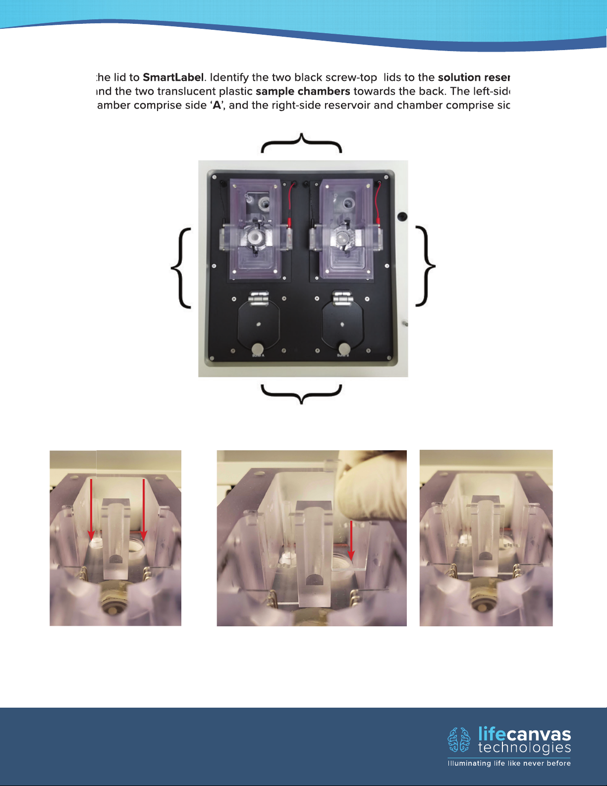
Open the lid to SmartLabel. Identify the two black screw-top lids to the solution reservoirs at the
SmartLabel
towards the back. The left-side reservoir
A
2
front, and the two translucent plastic sample chambers towards the back. The left-side reservoir
and chamber comprise side ‘A’, and the right-side reservoir and chamber comprise side ‘B’.
SAMPLE CHAMBERS
SIDE A
SIDE B
SOLUTION RESERVOIRS
Identify the two gaps in the
plastic (red arrows) located
halfway along the length of
the sample chamber.
INFO@LIFECANVASTECH.COM
LIFECANVASTECH.COM
Plastic spacers, which control the solution level in the front half of
the chamber where the sample cup is placed, need to be lowered
into place on each side of the chamber, as shown in the left image
above.
 Loading...