

Lifebreath 2500EFD User Manual
* LEAVE FOR HOMEOWNER
NOTE: Due to ongoing research and product development, specifications,
ratings and dimensions are subject to change without notice.
Installing Contractor
Telephone / Contact
Serial Number
Installation Date Model
TO BE COMPLETED BY CONTRACTOR AFTER INSTALLATION
CAUTION
Before
installation, careful consideration must be given to
how this system will operate if connected to any other piece
of mechanical equipment, i.e. a forced air furnace or air
handler, operating at a higher static. After
installation, the
compatibility
of the two pieces of equipment must be
confirmed by measuring the airflow’s of the Heat Recovery
Ventilator (HRV) Energy Recovery Ventilator (ERV) by
using the balancing procedure found in this manual.
It is always important to assess how the operation of any
HRV/ERV may interact with vented combustion equipment
(ie. Gas Furnaces, Oil Furnaces, Wood Stoves, etc.).
NEVER install a ventilator in a situation where its normal
operation, lack of operation or partial failure may result
in the backdrafting or improper functioning of vented
combustion equipment!!!
IMPORTANT - PLEASE READ THIS
MANUAL BEFORE INSTALLING UNIT
OPERATION AND
INSTALLATION MANUAL
TI-59
1203
For Models:
2500IFD
2500EFD

2
Introduction
These Heat Recovery Ventilators (HRVs) are designed
for commercial and industrial applications to provide
fresh air to a building while exhausting an equal
amount of stale air. During the winter months the
incoming cold fresh air is warmed by utilizing the heat
recovered from the stale air before it is exhausted to
the outdoors. During summer months when the indoor
space is air conditioned, the Heat Recovery Ventilator
will help in cooling the incoming fresh air with the stale
air that is being exhausted.
Table of Contents
Introduction .................................................................... 2
Select Correct HRV......................................................... 3
Specifications - Model 2500IFD .................................. 4
Specifications - Model 2500EFD ................................. 5
Options & Accessories ....................... 6
Operation Instructions ................................................... 7
Installation Tips ............................................................. 7
Remote Controls ........................................................... 8
User Adjustable Defrost ................................................ 8
Defrost Control .............................................................. 8
Fan Defrost ................................................................. 9
Location ...................................................................... 9
Mounting ..................................................................... 9
Drains ......................................................................... 12
Ducting ......................................................................... 12
Return and Supply ....................................................... 13
Air Flow Balancing ....................................................... 14
The Integrated HVAC System ...................................... 15
Electrical Connections ................................................. 15
Maintenance ................................................................ 15
Wiring Diagram ........................................................... 17
Ladder Diagram .......................................................... 18
Warranty .................................................................... 19
I F D
2500
Interior
mount
Fan
Defrost
E F D
2500
Exterior
(roof mount)
Fan
Defrost
3
MAKE UP HEAT REQUIREMENT at 1200 CFM (566L/s)
Nominal Nominal Nominal
Outdoor Temp. kW Req. for kW Req. for kW Req. for
C° F° 20°C (68°F) 25°C (77°F) 30°C (86°F)
Air Delivery Air Delivery Air Delivery
0 32 7 10 14
-10 14 10 14 17
-20 -4 12 15 19
-30 -22 15 19 22
-40 -40 17 21 24
Selecting the Correct Size HRV
Commercial and Institutional Requirements
For outdoor air requirements, ASHRAE has produced the Ventilation Standard 62-1989
that is used to determine acceptable ventilation rates. This standard is referenced directly or
used as “Good Engineering Practice” in most Code documents or design criteria.
Small restaurants, Donut Shops and Fast food stores
Seats 40
Employees 5
Total 45
ASHRAE requirement 20 cfm (10 L/s) per person
Ventilation required 45 x 20 = 900 cfm (450 L/s)
Bank
Customers 25
Staff 9
Total 34
ASHRAE requirement 20 cfm (10 L/s) per person
Ventilation required 34 x 20 = 680 cfm (320 L/s)
Bar or Tavern
Seats 50
Employees 7
Total 57
ASHRAE requirement 30 cfm (15 L/s) per person
Ventilation required 57 x 30 = 1710 cfm (855 L/s)
Bingo Hall
Customers 180
Staff 20
Total 200
ASHRAE requirement 30 cfm (15 L/s) per person
Ventilation required 200 x 30 = 6000 cfm (3000 L/s)
Classroom and School Portables
Seats 29
Teacher 1
Total 30
ASHRAE requirement 15 cfm (7.5 L/s) per person
Ventilation required 30 x 15 = 450 cfm (255 L/s)
Print Shop, Duplicating
Square footage of shop 2000 square ft
ASHRAE requirement 0.5 cfm / ft
2
(2.5 L/s - m2)
Ventilation required 2000 x 0.5 = 1000 cfm (500 L/s)
Beauty Salon
Customers 12
Employees 6
Total 18
ASHRAE requirement 25 cfm (12.5 L/s) per person
Ventilation required 18 x 25 = 450 cfm (255 L/s)
Swimming Pools
Refer to “Pool” Models Installation Manuals.
4
SPECIFICATIONS
AIR FLOW
2100 cfm (985 L/s) at 1.0"wg ESP
PERFORMANCE
70% effective at 2500 cfm (1172 L/s)
CORE
Modular aluminum sensible heat recovery core.
Plate-to-plate type. Slides out of either side of cabinet for
service.
MOTORS
Two single shaft PSC, 3-speed, 208/230V,5.1 amps,
1 ph, 1 hp
BLOWERS
Two direct-drive centrifugal blowers, one per air stream.
FILTERS
Two 18" X 24" 4-inch pleated filters in each air stream.
DUCT CONNECTIONS
Four 24" X 16" (610mm X 406mm)
CABINET
20 gauge powder coated galvanized steel (G60) for
superior corrosion resistance. 16 gauge galvanized
frame, insulated with1.5" fibreglass insulation to prevent
condensation.
DRAIN
Two stainless steel drain pans with 1/2" NPT drain
spouts.
MOUNTING
Unit to be set on support brackets hung by threaded rod
type apparatus. Brackets and rod not provided.
CONTROLS
24V terminal strip inside electrical box, to connect
optional remote controls (not included), obtain on/off and
high/low functions.
DEFROST
Factory set defrost time (user adjustable).
Supply motor is shut off while exhaust air defrosts core.
WARRANTY
15 year warranty on heat exchanger, and 2 years
on parts.
WEIGHT
700 lbs.
SHIPPING WEIGHT
1100 lbs.
All units conform to CSA and UL standards.
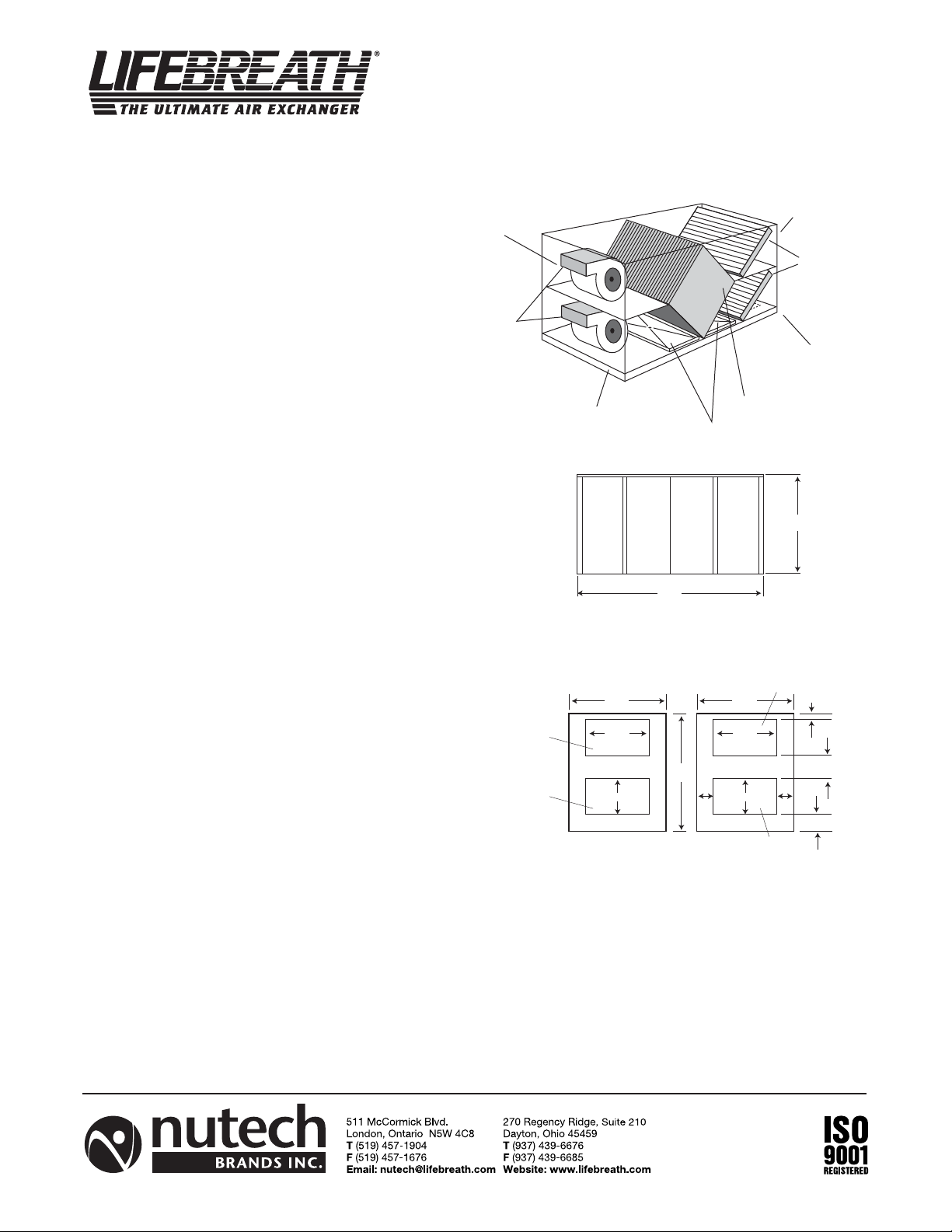
Model 2500IFD
DATE: ______________________________________________PROJECT: ______________________________________
MECHANICAL CONTRACTOR: _________________________________________________________________________
TI-91I
1203
Exhaust to Outside
Motors (2)
Exhaust to
Supply from Outside
Exhaust from Building
Supply to Building
Electrical
Service
Panel*
Heat
Exchanger
Service
Panel*
89.9"
SIDE VIEW
*NOTE: Removable service access panels on both sides of 2500IFD cabinet.
38.4"
outside
Supply to
building
24"
47"
16"
FRONT VIEW BACK VIEW
Heat Exchange Core
Drain Pans (2)
Filter
Service
Panel*
Supply from
outside
38.4"
24"
16"
Exhaust from
building
4" Filters
47"
2"
7"
6"
5
DATE: ____________________________________________PROJECT: ________________________________________
MECHANICAL CONTRACTOR:__________________________________________________________________________
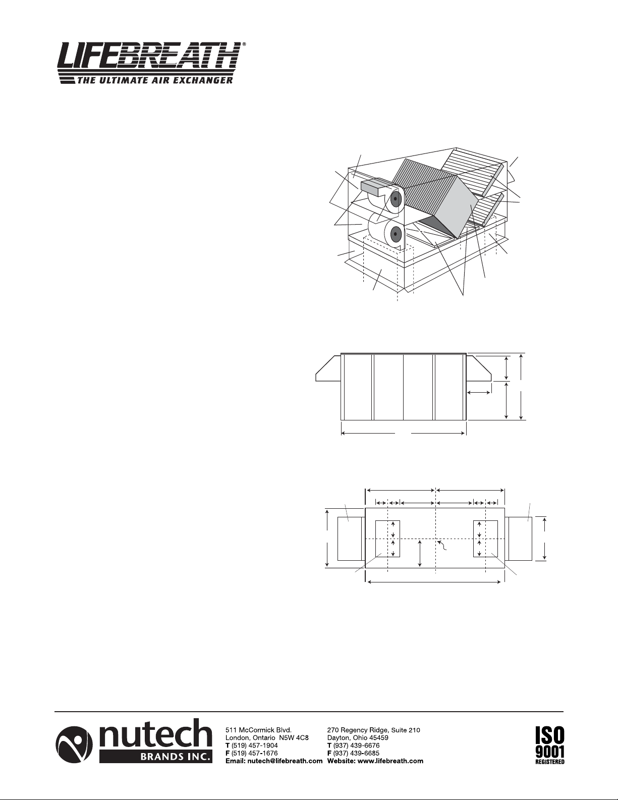
Model 2500EFD
(ROOFTOP)
TI-91E
1203
All units conform to CSA and UL standards.
SPECIFICATIONS
AIR FLOW
2100 cfm (985 L/s) at 1.0"wg ESP
PERFORMANCE
70% effective at 2500 cfm (1172 L/s)
CORE
Modular aluminum sensible heat recovery core.
Plate-to-plate type. Slides out of either side of cabinet
for service.
MOTORS
Two single shaft PSC, 3-speed, 208/230V,5.1 amps, 1 ph,
1 hp
BLOWERS
Two direct-drive centrifugal blowers, one per air stream.
FILTERS
Two 18" X 24" 4-inch pleated filters in each air stream.
DUCT CONNECTIONS
Four 24" X 16" (610mm X 406mm) to and from the building
under cabinet.
Four 28" X 18" (711mm X 457mm) hoods
included on side of cabinet with screens.
CABINET
20 gauge powder coated galvanized steel (G60) for
superior corrosion resistance. 16 gauge galvanized
frame, insulated with 1.5" fibreglass insulation to prevent condensation.
DRAIN
Two stainless steel drain pans with 1/2" NPT drain
spouts.
MOUNTING
Rooftop mounted on optional roof curb (Part No. 53-
2500)
CONTROLS
24V terminal strip inside electrical box, to connect
optional remote controls (not included), obtain on/off
and high/low functions.
DEFROST
Factory set defrost time (user adjustable).
Supply motor is shut off while exhaust air defrosts core.
WARRANTY
15 year warranty on heat exchanger, and 2 years on
parts.
WEIGHT
700 lbs.
SHIPPING WEIGHT
1100 lbs.
OPTIONAL CURB
WEIGHT 50 lbs.
Hoods (2)
c/w Bug Screen
Motors (2)
Roof Curb
*NOTE: Roof curb is one inch smaller than outside dimensions of cabinet.
*NOTE: Removable service access panels on both sides of 2500EFD cabinet.
38.4" 28"
Fresh Air
Supply
Exhaust
Hoods
Supply Duct
24"x16"
Electrical
Service
Panel*
Heat
Exchanger
Service
Panel*
89.9"
Filter
Service
Panel*
SIDE VIEW
44.95"
Hood Hood
8" 8"
12"
12"
21.8"
19.2"
89.9"
25"
Bottom duct
connections
16" X 24"
Centre
Point
44.95"
BOTTOM VIEW
Supply Hoods
Exhaust Duct
Heat Exchange Core
Drain Pans (2)
18"
18"
27"
8" 8"
12"
12"
4" Filters
24"x16"
47"
Stale Air
Return
6
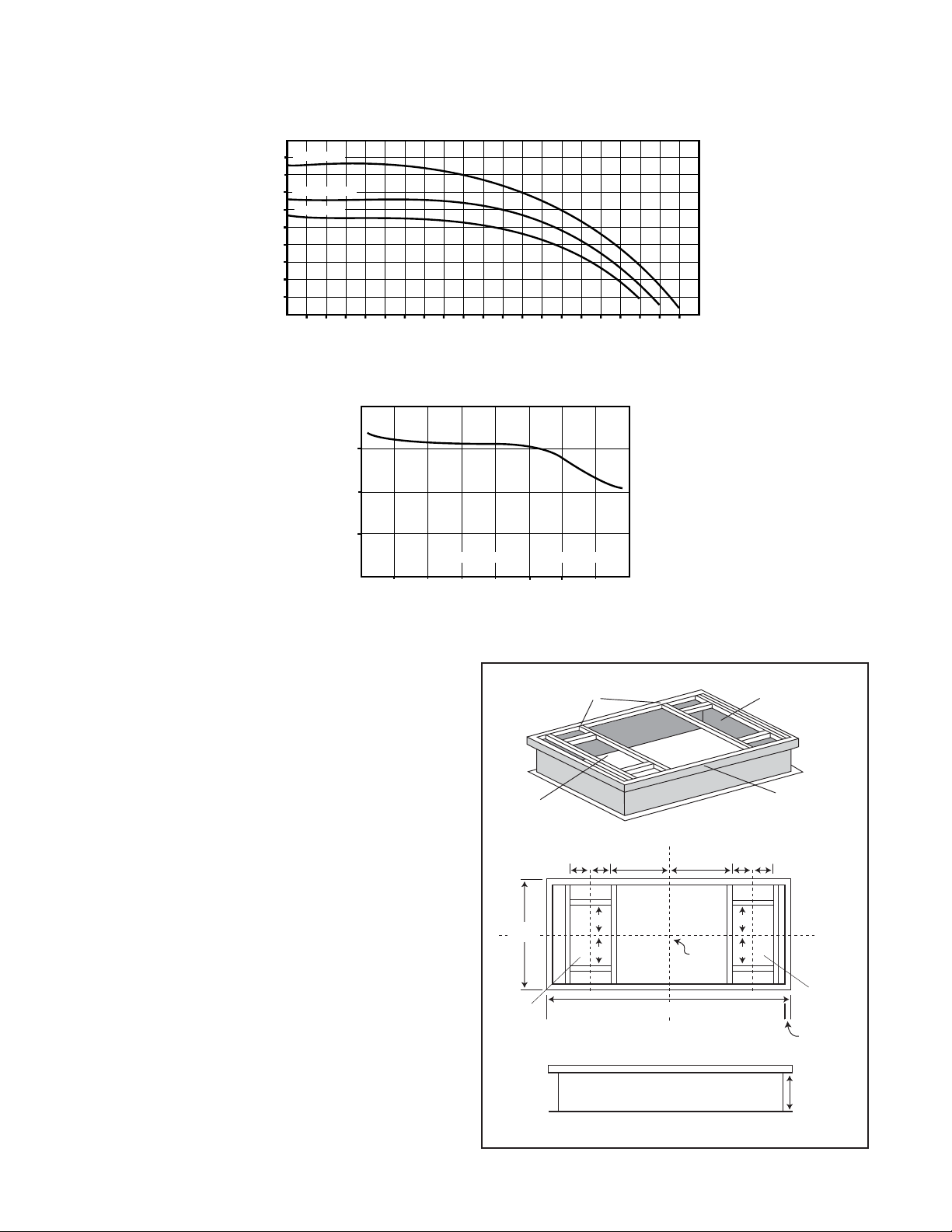
AIRFLOWS (Each Air Stream)
1316 (2800)
1175 (2500)
1034 (2200)
893 (1900)
752 (1600)
611 (1300)
470 (1000)
329 (700)
188 (400)
47 (100)
AIRFLOW L/s (CFM)
25
50 75 100 125 150 175 200 225 250 275 300 325 350 375
(
0.1
) (0.2) (0.3) (0.4) (0.5) (0.6) (0.7) (0.8) (0.9) (1.0) (1.1) (1.2) (1.3) (1.4) (1.5)
400 425 450 475 500 525 550
(1.6) (1.7) (1.8) (1.9) (2.0) (2.1) (2.2)
EXTERNAL STATIC PRESSURE IN PASCALS (in. W.C.)
70%
60%
50%
850
(1800)
944
(2000)
1039
(2200)
TEMPERATURE EFFECTIVENESS
AIRFLOW IN L/s (CFM)
NOTE: Exhaust Relative Humidity (RH) at 40%
EFFECTIVENESS
1133
(2400)
1228
(2600)
1322
(2800)
1416
(3000)
HIGH SPEEDHIGH SPEED
MEDIUM SPEEDMEDIUM SPEED
LOW SPEEDLOW SPEED
Performance
Options and Accessories
99-101: CRANK TIMER
Mechanical timer to activate high speed.
99-116: DEHUMIDISTAT VENTILATION CONTROL (DVC)
Turns unit on/off via slider switch and high/low via built-in
dehumidistat.
99-130: DEHUMIDISTAT
Activates high speed when indoor humidity
rises above set point on control.
99-140: 4" TECHGRILLE
99-141: 5" TECHGRILLE
99-142: 6" TECHGRILLE
99-148: 8" TECHGRILLE
Round, white, step-type diffusers.
53-2500: OPTIONAL ROOF CURB
Supports HRV on roof and connects
HRV to ducting below.
WEIGHT: 50lbs
Information about design-built electric make-up heat
coils available upon request.
Roof Curb (optional)
Part No. 53-2500
Duct Collar Supports
Return air
opening
8" 8"
36.5"
Fresh Air
Supply
12"
12"
21.8"
Bottom duct
connections
16" X 24"
Centre
Point
88.5"
TOP VIEW
Supply air
opening
Factory installed
perimeter wooden
nailer strip
8" 8"
25"
12"
12"
14"
Stale Air
Return
0.7"
SIDE VIEW
 Loading...