

Lifebreath 155MAX series, 155MAXRX series, 200MAX series, 95MAX series, 200MAXRX series Operation And Installation Manual
...
Operation and Installation Manual
Max Series
5 Speed Electronics
Lifestyle MAX Digital Control included
95MAX*
155MAX
155ECM*
155MAXRX
200MAX*
200MAXRX*
195DCS*
195ECM*
300DCS*
Residential Heat Recovery Ventilators (HRV)
*
This product earned the EERGY STAR by
meeting strict energy efficiency guidelines set by
atural Resources Canada and the US EPA. It
meets EERGY STAR requirements only when
used in Canada.
69-MaxSeries
1011
Table of Contents
CAUTION
WARNING
Max Series Electronics..................................................................2
Getting to Know your MAX Series HRV
Selecting the Ventilation Rate that is right for You
How the Dehmidistat Works
Glossary of Additional Information
Warranty........................................................................................3
The Lifestyle MAX Digital Control..............................................4
The Lifestyle MAX Programmable Control .................................5
Optional Timers ............................................................................6
Maintenance Routine for HRV .....................................................7
Technical Data - Model 95MAX ...............................................8-9
Technical Data - Model 155MAX ..............................................10
Technical Data - Model 155MAX RX........................................11
Technical Data - Model 155ECM ...............................................12
Technical Data - Model 200MAX ..............................................13
Technical Data - Model 200MAX RX .......................................14
Technical Data - Model 195DCS................................................15
Technical Data - Model 195ECM ...............................................16
Technical Data - Model 300DCS................................................17
Installation Methods....................................................................18
Installation Diagrams.............................................................19-21
Installation...................................................................................22
Drain Connection
Grilles .........................................................................................23
Grille Fittings .............................................................................24
Weatherhood Installation ............................................................25
Installation of the Main Control..................................................26
Installation and Operation 20/40/60/ Minute Timers
Installation of Mechanical Timers...............................................27
Interlocking the HRV to an Airhandler/Furnace Blower
Setting “Standby” when using a Main Control
Operating the HRV without a Main Control and Adding
Dry Contact Controls ..................................................................28
Balancing the Air Flows..............................................................29
Balancing the Air Flows with a Pitot Tube.................................30
Air Flow Balancing using the Door Ports ...................................31
Balancing Collar Instructions
Balancing Instruments and Kits ..................................................32
Troubleshooting your HRV System............................................33
Wiring Diagrams....................................................................34-35
IMPORTANT -
PLEASE READ THIS MANUAL BEFORE
INSTALLING UNIT.
• Due to ongoing research and product
development, specifications, ratings and
dimensions are subject to change without notice.
Before installation, careful consideration must be
given to how this system will operate if connected
to any other piece of mechanical equipment, i.e. a
forced air furnace or air handler, operating at a
higher static. After installation, the compatibility of
the two pieces of equipment must be confirmed, by
measuring the air flows of the HRV, by using the
balancing procedure found in this manual.
NEVER install a ventilator in a situation where its
no rmal operatio n, lack of operat io n or partial
failure may result in the backdrafting or improper
functioning of vented combustion equipment.
• Disconnect the power from the unit before
cleaning or servicing.
• To prevent electrical shock, it is extremely
important to confirm the polarity of the power line
that is switched by the safety (disconnect) switch.
The hot line (black) is the proper line for switching.
Use either a voltmeter or test lamp to confirm the
absence of a voltage between the disconnect
switch and ground (on the cabinet) while the door
is open. This procedure must be followed, as
dwellings are occasionally wired improperly.
Always enure the proper grounding of the unit.
• Do not apply electrical power to the unit until after
the completion of the installation (including the
installation of low voltage control wiring).
• Ensure the Installation and wiring is in
accordance with CEC, NEC, and local electrical
codes.
• Due to ongoing research and product
development, specifications, ratings and
dimensions are subject to change without notice.
•
Plug the unit into a standard designated (120 VAC)
electrical outlet with ground.
•The use of an extension cord with this unit is not
recommended. If the installation requires further
wiring, have a licensed electrician make all of the
electrical connections. The recommended circuit is a
separate 15 amp/120 volt circuit.
2

Getting to Know your MAX Series Heat Recovery Ventilator (HRV)
Thank you for purchasing a LIFEBREATH® Heat Recovery Ventilator
(HRV). The HRV provides fresh air to your home while recovering energy
from the air it exhausts.
There are numerous benefits to a properly installed, operated, and
maintained HRV:
• exhausts the stale, contaminated air, found in today’s tight buildings.
• recovers the majority of the energy contained in the exhausted stale air.
• uses the recovered energy to preheat or precool the fresh outdoor air
introduced into the house.
• distributes the fresh air throughout your home.
Selecting the Ventilation Rate that is right for You
The modes of operation and speeds are used to adjust your indoor
ventilation rate. Experiment with the ventilation levels in your home to
evaluate the ideal amount of ventilation to suit your home and personal
preferences. Your Lifebreath MAX SERIES HRV main control has
4 Modes of Operation* and 5 speeds on each mode.
I. CONTINUOUS VENTILATION
This mode of operation provides continuous ventilation within the home.
You may, for example, select Continuous Ventilation at a low speed (speeds
1 or 2) for normal operation and increase to a higher speed (speeds 3 to 5)
during increased activity levels, such as cooking and showering, etc.
II. 20 MINUTES ON, 40 MINUTES STANDBY
This mode of operation provides 20 minutes of ventilation each hour. You
can use this ventilation mode at low speed for low household activity levels
or when the home is unoccupied.
III. 20 MINUTES ON, 40 MINUTES RECIRCULATION *
Ventilates for 20 minutes and recirculates the household air every
40 minutes each hour. This mode is non-applicable if your HRV is
connected to a forced air system (the forced air system already circulates
household air).
IV. CONTINUOUS RECIRCULATION *
Continuously recirculates your household air (no ventilation). This mode is
non-applicable if your HRV is connected to a forced air system.
* If your HRV is connected to a forced air system, recirculation (modes III
and IV) is unavailable and non-applicable on all models.
RECIRCULATION - recirculates existing household air without
introducing fresh air. Recirculation Modes (III and IV) are
non-applicable if your HRV is connected to a forced air system, since your
forced air system already circulates the household air. Recirculation Modes
are unavailable on some models.
How the Dehumidistat Works
High indoor humidity levels, during the heating season, have become a
problem in many well insulated, tight homes. Excessive condensation on the
windows is a visual sign of high indoor humidity levels. High indoor
humidity levels can result in mold and mildew and the eventual degradation
of the building structure itself.
Your HRV reduces indoor humidity levels when the outdoor air is drier than
the indoor air. These conditions usually occur during the heating season
when outdoor temperatures are less than 15°C (59°F). During the heating
season, the operation of the HRV may reduce indoor humidity levels
sufficiently to eliminate the need for further dehumidification.
If your home requires further dehumidification, use the dehumidistat feature
located on the main control. This feature aggressively addresses high indoor
humidity levels by initiating high speed ventilation when the indoor
humidity levels rise above the adjustable set point on the control.
Refer to the main control instructions located in the Operation and
Installation Manual for instructions on how to set the dehumidistat.
The dehumidistat function should be set to OFF for all seasons except the
heating season, because a dehumidifying effect occurs only when the
outdoor air is dryer than the indoor air. Set the RH level to 80 to turn the
dehumidistat OFF. (Refer to the control instructions for information on how
to set the Dehumidistat).
DEHUMIDISTAT DISABLE - automatically disables the dehumidistat
function on the main control when outdoor temperatures exceed 15°C
(59°F) for a full 24 hour period. All other HRV features and functions
operate normally while the dehumidistat function is disabled.
DEHUMIDISTAT RE-EABLE - automatically re-enables the
dehumidistat function if either the outdoor temperature drops below 15°C
(59°F) for a full 24 hour period or if the HRV is reset (unplugged for 30
seconds).
Glossary and Additional Information
DEFROST MODE - To ensure reliable operation during cold weather, the
HRV automatically cycles through its defrost mode when the outdoor
temperatures drop below freezing.
HRV - a Heat Recovery Ventilator (HRV) is designed to provide fresh air
into a building while exhausting an equal amount of stale air. During the
winter months, heat recovered from the stale air, before it is
exhausted to the outdoors, warms the incoming cold fresh air. During the
summer months, when the indoor space is air conditioned, the HRV helps to
cool the incoming fresh air with the cool exhausted stale air.
MAITEACE ROUTIE - Homeowner maintenance should be
performed as per "Maintenance Routine for HRV" located in the
Operation and Installation Manual.
Warranty
Lifebreath MAX Series Heat Recovery Ventilators carry a Lifetime
Warranty on the heat recovery core and a 5 (five) year replacement
parts warranty.
OPERATIO AD ISTALLATIO MAUAL - Contains
instructions and important information regarding your HRV and controls.
You can download the manual at www.lifebreath.com
SELF-TEST - Each time the HRV is powered/energized, the self-test
function automatically initiates. The HRV cycles through the available
speeds and tests the damper motor operation. The HRV defaults back to the
previous operational mode and speed selection after the self-test
(approximately 60 seconds in duration).
STADBY (Speed 0) - The HRV is powered/energized and waiting for
ventilation to be initiated by either an external control (i.e. timer) or the
dehumidistat. Set the main control to speed 0 to set the HRV in standby.
TIMERS - These optional controls may be installed at specific exhaust
locations (bathrooms etc.) to initiate high speed ventilation.
.
Register for your warranty at:
www.lifebreath.com
or phone 1-855-247-4200 (toll free)
OTE: Airia will require the HRV Model and Serial Number(s) for
the registration of your HRV.
3
How the Dehumidistat Works
Your Lifestyle MAX Digital Control or the optional Lifestyle
MAX Programmable Control has an adjustable dehumidistat
which can be set to achieve a further dehumidification effect from
your HRV. High speed ventilation will be initiated upon exceeding
the dehumidistat set point regardless of the mode and speed of
operation. Once the humidity in the house is reduced, the HRV
will revert back to its previous setting.
We suggest operating the HRV for the first few days without use
of the dehumidis ta t f un ction to obser ve i f a fur th er
dehumidifi cation e ffect will b e required . The dehumidistat
operates in % of RH (relative humidity) with 80 being high and
20 being low. Set the Dehumidistat to 80% to disable. If, after a
few days, further dehumidification is required (the house is still
too humid), set the humidity level to a lower amount.
How to Synchronize the Humidity Setting
The Lifestyle Digital wall control has a feature that will allow it to
be synchronized with other humidity instruments in your home.
1. Turn off the control with the ON/OFF button.
2. Simultaneously press and release the ON/OFF button and the
3. Use the Up/Down buttons to adjust the Humidity Indicator on
The average person is comfortable between 30-50% RH. The
dehumidistat should be set to OFF for all seasons except the
heating season. OFF is achieved by setting the dehumidistat to 80.
4. Press the MODE button.
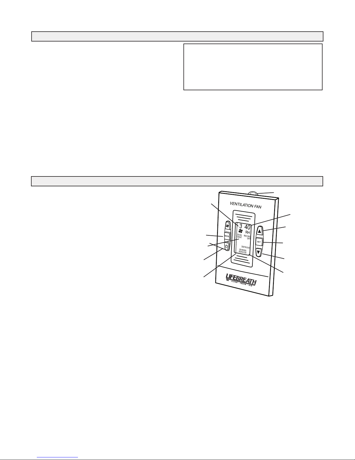
The Lifestyle MAX Digital Control (Included Wall Control)
Part # 99-DXPL01
The Lifestyle MAX Digital Control is fully digital and allows you to
easily control your home's ventilation.
Key Features
• 5 Speed Fan setting
• Electronic Dehumidistat
• Four Selectable Modes of Operation
20 min. ON / 40 min. off, 20 min. ON / 40 min. recirculate *
Continuous Ventilation, Continuous Circulation *
• 20 / 40 /60 High Speed override timer
• Service/Maintenance Reminder display
• Backlit LCD screen is easy to read
* Recirculation not available on all models
Setting the Control
1. Refresh the screen: use the ON/OFF button to turn the control OFF and
ON.
2. Press the SET button.
3. The “FAN” symbol flashes. SCROLL (by using the Up/Down arrows)
to select the desired fan speed (0, 1 or 2). Press the SET button.
4. “VENT”, “20/40”, “20/40 RECIRC”, “RECIRC”or “OFF” will flash.
SCROLL to select the desired mode of operation. Press SET button.
*R EC IR C is no t avai la bl e on al l models .
**Timers will not function when mode of operation is set to “OFF”.
Setting the Dehumidistat
1. Refresh the screen: use the ON/OFF button to turn the control OFF and
ON.
2. Press and release MODE until “RH” flashes.
3. SCROLL to the desired RH number. Press the MODE button.
20/40/60 Minute
High Speed
Override Button
20/40/60 Minute High Speed Timer
This function temporarily initiates high speed ventilation for 20, 40 or 60
minutes.
1. R efr esh th e sc ree n: u se t he O N/OFF but ton to turn the control
2. Press FAN button once for 20, two times for 40, three times for
Service Indicator
A ‘ SE RV IC E’ in di ca to r d isplays once every 4 m on ths. Re fe r to
"Maintenance Routine" in the Operation & Installation manual.
To reset the service indicator:
1. Refresh the screen: use the ON/OFF button to turn the control OFF and
2. Press and release the Up and Down buttons simultaneously. The
3. Press SET within the 5 seconds and the service indicator will reset.
Dehumidistat Notes:
The dehum id is ta t functio n wi ll b e disabled if o utdoor
temperatures exceed 15°C (59°F) for a 24 hour period.
The dehumidistat function will be re-enabled if the unit is
unplugged for 3 minutes or if the outdoor temperature drops
below 15°C (59°F) for a 24 hour period.
20/40/60 Minute High Speed override button.
the display screen to the number of degrees difference between
your humidity meas uring devi ce. Minus i s indicated b y
flashing.
nstruction card
I
Fan Speed
Indicator
Mode Select
Button
Mode
Indicator
ON/OFF
Button
High Speed
Override
Timer
Indicator
Connects to 3 wire 20 gauge
low voltage wire
OFF and ON.
60 minutes, and four times to cancel the timer.
ON.
“SERVICE” icon will flash for 5 seconds.
Humidity
Indicator
Up Button
Set button
Down Button
Service
Indicator
4
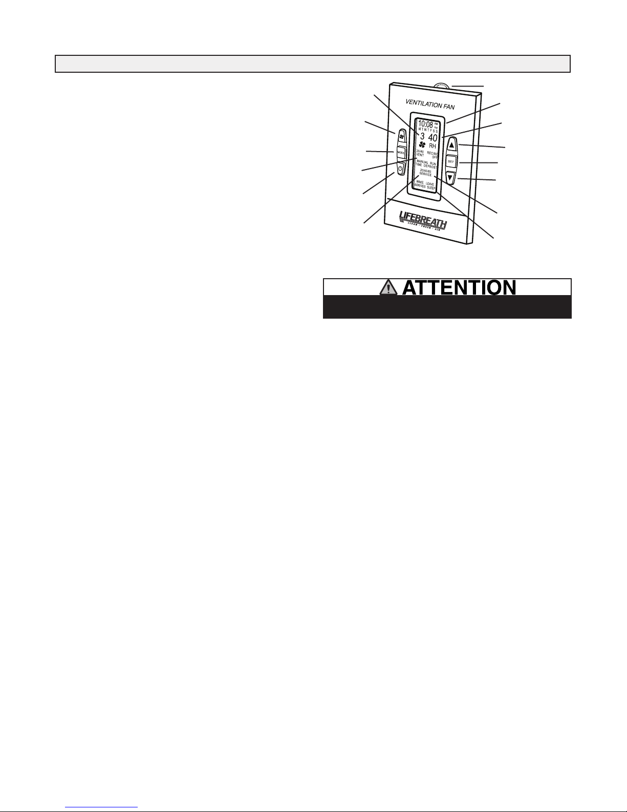
The Lifestyle MAX Programmable Control (Optional)
Part # 99-LS-01
The optional Lifestyle MAX Programmable Control is fully digital and
allows you to program when and how much fresh air will be entering your
home.
Key Features
• 24 / 7 programmable ventilation • 4 programmable events per day
• 5 Speed Fan setting • Electronic Dehumidistat
• Four Selectable Modes of Operation
20 min. ON / 40 min. off, 20 min. ON / 40 min. recirculate *
Continuous Ventilation, Continuous Recirculation *
• 20 / 40 /60 High Speed override timer
• Service/Maintenance Reminder display
• Easy to read Backlit LCD screen
Setting Date & Time
1. R efr esh the screen: use the ON/OFF button to tur n th e co ntr ol
OFF and ON.
2. Press and release the MODE button until "TIME" and "SET" appear
on the screen. Press SET Button.
3. The letter for the day of the week flashes. SCROLL (using Up/Down
arrows) to the correct day of the week. Press the SET button.
4. The hour and "AM" or "PM" flashes. SCROLL to the correct hour and
press the SET button.
5. The minutes will flash. SCROLL to the correct minute. Press the SET
button.
Programming Your Control
1. R efr esh the screen: use the ON/OFF button to tur n th e co ntr ol
OFF and ON.
2. Press and release the MODE button until "PROGRAM SET" appears
on the screen. Press SET.
3. Weekday letters (MTWTF) will flash. Press SET.
4. "WAKE" flashes. Press SET.
5. "AM" or "PM" flashes. SCRO LL to desired time (in 20 minute
intervals). Press SET.
6. The "FAN" symbol flashes. SCROLL to the desired fan speed (0-5).
Press SET.
7. “VENT”, “20/40”, “20/40 RECIRC*”, “RECIRC*”, “OFF” will flash.
SCROLL to the desired mode of operation. Press SET two times.
(Refer to Manual for an explanation of the modes of operation.)
8. "LEAVE" flashes. Press SET. Repeat steps 4 to 6 to program four
events per day.
9. “SS” (Saturday & Sunday) flashes. Press SET. Repeat steps 3 to 7 to
program the weekend events.
Programming Individual Weekday Events
After performing the MTWTF and SS programming functions, you can
program individual weekday events.
1. R efr esh the screen: use the ON/OFF button to turn th e co ntr ol
OFF and ON.
2. Press and release the MODE Button until "PROGRAM SET" appears
on the screen. Press SET.
3. Weekday letters (MTWTF) will flash. Scroll to the desired weekday
(M,T,W,T,F,S,S). Press SET.
4. “WAKE” flashes. Scroll to the desired event that you want to program
as a custom setting (“WAKE”, “AWAY”, “RETURN” or “SLEEP”.
Press SET.
5. Either “AM” or “PM” flashes. SCROLL to the desired time (available
in 20 minute intervals). Press SET.
6. “FAN” flashes. SCROLL to desired fan speed (0 - 5). Press SET.
7. “VENT”, “20/40”, “20/40 RECIRC*”, “RECIRC*” or “OFF” will
flash. SCROLL to the desired mode of operation. Press SET. (Refer to
Manual for explanation of operational modes.)
8. More weekday events are programmable by pressing SET and repeating
steps 4 to 7.
nstruction card
Fan Speed
Indicator
20/40/60 Minute
igh Speed
H
Override Button
Mode Select
utton
B
Mode
ndicator
I
ON/OFF
utton
B
High Speed
Override
Timer
ndicator
I
Connects to 3 wire 20 gauge
low voltage wire
I
ate & Time
D
umidity
H
Indicator
Up Button
et button
S
ecrease
D
Button
Service
ndicator
I
aytime
D
Event
rogram
P
Indicator
Only one main control can be installed on your system.
Running the Program
Upon completion of the programming, you must activate the program.
1. Refresh the screen: use the ON/OFF button to turn the control
OFF and ON.
2. Press MODE until the program indicates “PROGRAM” and “RUN”.
Manually Setting the Control
1. Refresh the screen: use the ON/ OFF button t o turn th e control
OFF and ON.
2. Press and release MODE until the program indicates "MANUAL" and
"RUN”. Press SET.
3. When the FAN symbol flashes, SCROLL (use the Up/Down arrows)
to the desired fan speed (0-5). Press SET.
4. V EN T, 20/40 , 2 0/40 R EC IRC*, RE CI RC* or OFF w ill flas h.
SCROLL to the desired mode of operation. Press SET.
NOTE: The control remains in the “MANUAL RUN” position until you
ch an ge b ac k to “P RO GR AM R UN ” (R ef er t o “Run ni ng th e
Programmed Setting ). *RECIRC is not available on all mod els.
**Timers will not function when mode of operation is set to “OFF”.
Setting the Dehumidistat
Refer to "How the Dehumidistat Works" in this manual before setting the
Dehumidistat.
1. R efr esh th e sc ree n: u se t he O N/OFF but ton to turn the control
OFF and ON.
2. Press and release MODE until "RH" and a number flashes.
3. SCROLL to the desired RH number. Press the MODE.
20/40/60 Minute High Speed Timer
This function temporarily initiates high speed ventilation for 20, 40 or
60 minutes.
1. R efr esh th e sc ree n: u se t he O N/OFF but ton to turn the control
OFF and ON.
2. Press the FAN button once for 20, twice for 40 and three times for
60 minutes and four times to cancel the timer.
Service Indicator
A ‘ SE RV IC E’ in di ca to r d isplays once every 4 m on ths. Re fe r to
"Maintenance Routine" in the Operation & Installation manual.
To reset the service indicator:
1. Refresh the screen: use the ON/OFF button to turn the control OFF and
ON.
2. Press and release the Up and Down buttons simultaneously. The
“SERVICE” icon will flash for 5 seconds.
3. Press SET within the 5 seconds and the service indicator will reset.
5
Optional Timers
%
80
2
0
Depending on the type of HRV installation, you may have timers
in areas such as restrooms. The timer will override the Operational
Mode (regardless of the setting) and initiate high speed ventilation.
Upon completion of the timer cycle, the HRV will return to your
selected Operational Mode and speed setting
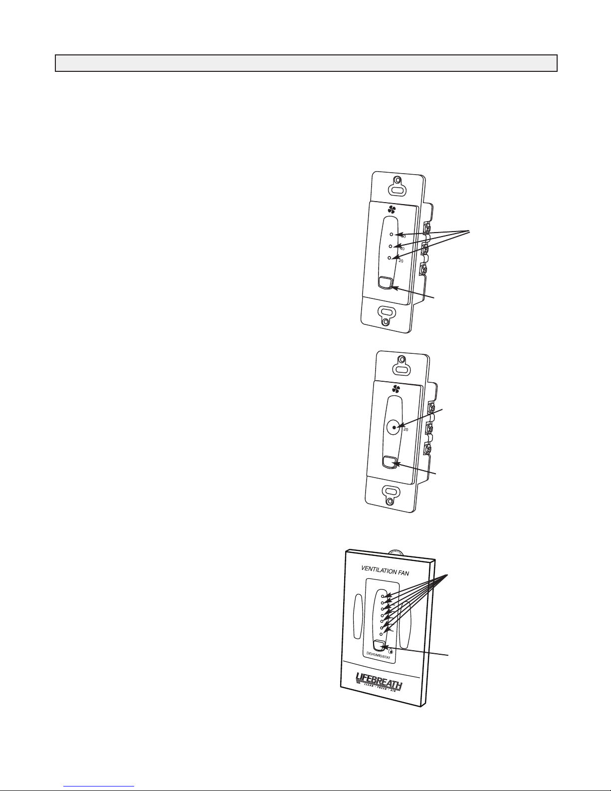
Lifestyle 20/40/60 Minute Timer
Part # 99-DET01
Initiates high speed ventilation for 20, 40 or 60 minutes. The
20/40/60 Minute Status Lights indicate high speed operation.
Lockout Mode is useful if you wish to disable the timer. Set
lockout by holding the Select Button for 5 seconds. Unlock by
holding for 5 seconds.
20 /40/60 Min ut e
Status Lights
Select Button
Lifestyle 20 Minute Timer
Part # 99-20M01
Initiates high speed ventilation for 20 minutes. The 20 Minute
Status Light indicates high speed operation.
Lockout Mode is useful if you wish to disable the timer. Set
lockout by holding the Select Button for 5 seconds. Unlock by
holding for 5 seconds.
Lifestyle Dehumidistat
Part # 99-DH-01
Initiates high speed ventilation when the moisture level in the
home exceeds the set point on the control. Once the humidity in
the house is reduced, the HRV will revert back to its previous
setting. The Dehumidistat should be set to OFF for all season
except the heating season.
Refer to "How the Dehumidistat Works" in this manual before
setting the Dehumidistat.
20 Minute
Status Lights
Select Button
Dehumidistat LEDs
Set to the desired humidity
level. High speed ventilation
will initiate when the indoor
moisture level exceeds the
set point on the control.
Dehumidistat
Adjust Button
6
Maintenance Routine for HRV
Electric shock hazard. Can cause
injury or death. Before attempting to
perform any service or maintenance,
turn the electrical power unit OFF at
disconnect switch(es). Unit may
have multiple power supplies.
WARNING
1. Inspect Exterior Hoods at least once a month.
Make sure exhaust and fresh air supply hoods are not blocked or
restricted by leaves, grass, or snow. In winter, it is especially
important to make sure snow is not blocking the hoods or that frost
has not built up on the wire mesh (bird screen).
WARIG: Blockage of hoods may cause an imbalance.
2. Clean Air Filters (clean twice a year)
The standard filters equipped with your HRV are removable and
washable.
a) open access door and slide core out.
b) remove filter clips if present.
c) once clips are removed, filters can be taken off the core to be
rinsed with water or a combination of mild soap and water. Do
not clean in the dishwasher.
d) to re-assemble, place clean filter(s) (wet or dry) back into their
positions against the core and return clips to their original
positions.
e) slide core back into its original position.
••
Do not use cleaning solutions for the HRV Core
•• SSooaakk aanndd rriinnssee tthhee HHRRVV ccoorree iinn wwaarrmm ssooaappyy wwaatteerr
•• DDoo nnoott uussee bblleeaacchh oorr cchhlloorriinnee
•• DDoo nnoott uussee aa pprreessssuurree wwaasshheerr oonn tthhee HHRRVV ccoorree
•• DDoo nnoott ppllaaccee tthhee HHRRVV ccoorree iinn aa ddiisshhwwaasshheerr
3. Clean Core Twice a Year
a) open access door.
b) carefully grip ends of core and pull evenly outward. Core may
be snug, but will slide out of the channel.
c) once removed from the cabinet remove filters.
d) install the clean filters.
e) install clean core.
ote: Core installation label on the outer end of the core.
To install the clean core:
a) first mount the bottom flange of the core guide into the bottom
H channel approximately 1/4” (6mm).
b) m ou nt t he left o r ri gh t side fla ng e of t he c ore guide
approximately 1/4” (6mm) followed by the other side.
c) mount the top flange of the core guide into the top H channel
approximately 1/4” (6mm).
d) with all four corners in place and the core straight and even,
push hard in the center of the core until the core stops at the
back of the cabinet.
OTE: Core will appear to stic k out from c abinet approximat ely
1/8” (3mm). This is designed this way so that the access door will fit
tight against the core.
4. Motors - Maintenance Free
5. Drain (condensate) Line - Clean once a year
Inspect drain line, drain spout and “P” trap for blockage, mold or
kinks. Flush with warm soapy water and replace if worn, bent or
unable to clean.
6. Clean Duct Work if Required
The duct work running to and from the HRV may accumulate dirt.
Wipe and vacuum the duct once every year. You may wish to
contact a Heating/Ventilation company to do this.
7. General Maintenance - Twice a Year
Wipe down the inside of the cabinet with a damp cloth to remove
dirt, bugs and debris that may be present.
8. Cleaning the Fans
Fans may accumulate dirt causing an imbalance and/or excessive
vibration of the HRV. A reduction in the air flow may also occur.
In new construction this may result within the first year due to
heavy dust and may occu r p eriodically afte r t hat over time
depending on the outdoor conditions.
• unplug the HRV and open the service door
• remove the core
• remove ducting (metal and/or flexible insulated type) from
the red and/or blue ports which are connected immediately
in-line with the fan assembly
• use a small brush, such as an old toothbrush or pipe cleaner,
and insert first
(a) through the large opening of the fan
assembly and then
(b) through the smaller opening in the end
of the fan assembly.
• scrub individual fan blades until clean. Avoid moving or
damaging balancing flat weight, clip is usually found on one
or more of the fan blades
• vacuum and wipe
• reassemble making sure ducting is reattached firmly and
insulation and moisture barrier are sealed and taped
Before attempting this task, thought should be given to having a
qualified service technician complete the service work.
7
Removable
Heat Recovery
Core
Drain Pan
Drain spout
FRONT TOP
minimum
18 inches (45 9 mm)
required for
service ac cess
Threaded
inserts (4 )
at corners
SUPPLY
Fresh air
from outside
5" round coll ar
SUPPLY
Fresh air
to building
6" round
(conv. to oval)
collar
EXHAUST
Stale Air
to outside
5" round coll ar
EXHAUST
Return air
from building
6" round (conv. to oval)
collar
18.5"
(470 mm)
18.5"
(470 mm)
16"
(406 mm)
SIDE
Hanging
straps (4)
24.5"
(622 mm)
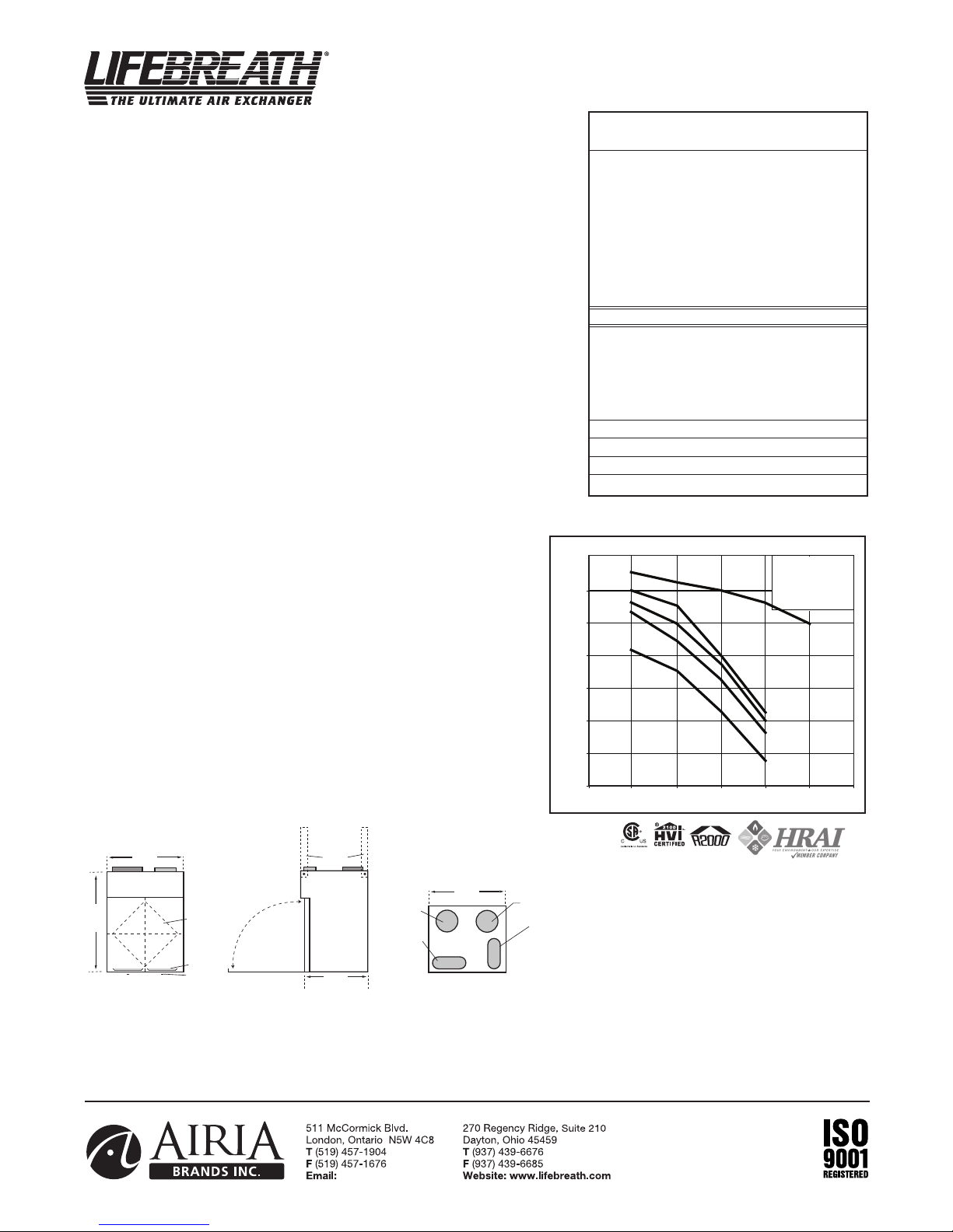
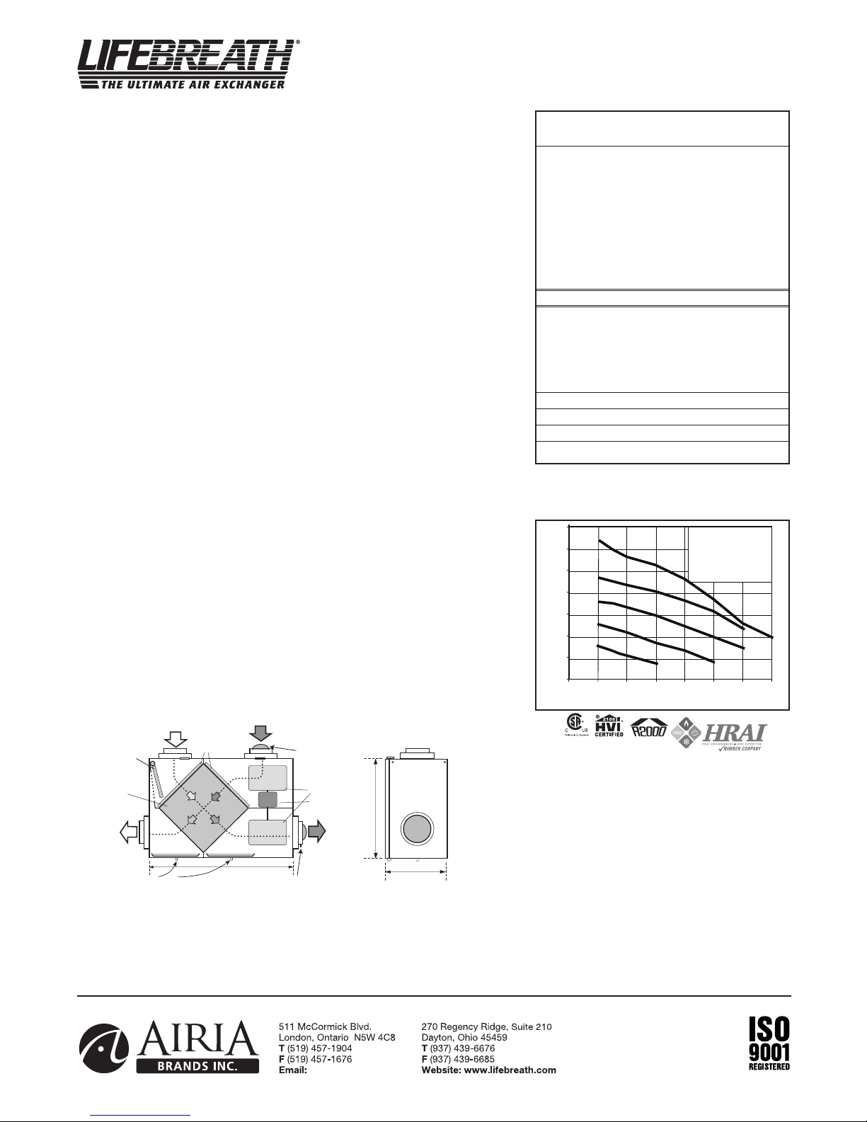
Model 95MAX
info@lifebreath.com
Static Pressure (in w.g.)
Air Flow (cfm)
Speed 5
Speed 4
Speed 3
Speed 2
Speed 1
20
30
40
50
60
70
0 0.1 0.2 0.3 0.4 0.5 0.6
80
4 - Medium High Speed
3 - Medium Speed
2 - Medium Low Speed
1 - Low Speed
5 - High Speed
ENGINEERING DATA
THERMALLY CONDUCTIVE, PATENTED ALUMINUM CORE
The cross-flow heat recovery core transfers heat between the two airstreams. It is easily
removed for cleaning or service.
MOTORS AND BLOWERS
Each air stream has one centrifugal blower driven by a common PSC motor. 5 speed fan
operation.
FILTERS
Washable air filters in exhaust and supply air streams.
MOUNTING THE HRV
Four threaded inserts at corners of the cabinet designed to accept the “S” hooks and
hanging straps supplied with the unit.
DEFROST
Recirculating defrost system.
CASE
Twenty gauge prepainted galvanized steel (G60) for superior corrosion resistance. Insulated
to prevent exterior condensation. Drain connections 2 - 1/2" (12 mm) OD.
WEIGHT 52 lbs. (23.6 kg) SHIPPING WEIGHT 56 lbs. (25.4 kg)
CONTROLS & ELECTRONICS
The Lifestyle MAX Digital Control (included with unit) can be wall mounted in a central
location of the home. (3 wire) 20 gauge wire (min.) 100' length
Electronic features include:
• 5 Speed Operation on each mode
• 4 user selectable operational modes: Continuous Ventilation, 20 ON/40 OFF,
20 ON/40 Recirculation, Continuous Recirculation
• Humidity Control through dehumidistat
• Adjustable Dehumidistat function built into the main wall control
• Built-in Relay for Interfacing to furnace
OPTIONAL PROGRAMMABLE CONTROL
99-LS-01 Lifestyle MAX Programmable Control - contains all the features of the
Lifestyle MAX Digital Control with 7/24 programmable ventilation, (3 wire)
20 gauge wire (min.) 100' length
OPTIONAL TIMERS
99-DET01 Lifestyle 20/40/60 Minute Timer - Initiates high speed ventilation for 20,
40, or 60 minutes, (3 wire) 20 gauge wire (min.) 100' length
99-20M01 Lifestyle 20 Minute Timer - Initiates high speed ventilation for 20 minutes,
(3 wire) 20 gauge wire (min.) 100’ length.
99-101 Mechanical Timer - Initiates High speed ventilation for up to 60 minutes,
(2 wire) 20 gauge wire (min.) 100' length
OPTIONAL ACCESSORIES
99-DH-01 Lifestyle Dehumidistat - Initiates high speed ventilation when the indoor
humidity level is above the set point. (3 wire) 20 gauge wire (min.) 100'
length
99-163 Duct Heater w/ Electronic SCR Thermostat, 1 Kw, 6” (150 mm)
99-185 Weatherhoods, Two - 5” (125 mm) c/w 1/4” (6 mm) mesh screen
Performance (
Net supply air flow in cfm (L/s) against external static pressure
.S.P
E
HVI certified)
(external static pressure) [cfm (L/s)]
0.1" (25 Pa) 76 (36)
@
@ 0.2" (50 Pa) 73 (34)
@ 0.3" (75 Pa) 70 (33)
@ 0.4" (100 Pa) 66 (31)
@ 0.5" (125 Pa) 60 (29)
Max. Temperature Recovery 88%
Sensible Effectiveness
@ 60 cfm (28 L/s) 32°F (0°C) 88%
*Sensible Efficiency
@ 60 cfm (28 L/s) 32°F (0°C) 75%
*Sensible Efficiency
@ 61 cfm (29 L/s) -13°F (-25°C) 68%
VAC @ 60HZ 120
WATTS / Low speed. 59
WATTS / High speed 89
Amp rating 0.9
*Sensible Efficiency – thermal **Latent Efficiency – moisture
ote: Effectiveness - based on temp. differential between the 2 airstreams
Efficiency – takes into account all power inputs
DIMENSIONS 95MAXinches (mm)
Date: ___________________________________________
Tag: _____________________Qty:___________________
Project: _________________________________________
Engineer: _______________________________________
8
All units conform to CSA and UL standards.
WARRANTY
Units carry a LIFETIME warranty on the heat
recovery core and a 5 year replacement parts
warranty.
Contractor: ______________________________________
Supplier: ________________________________________
Quote#: _________________________________________
Submitted by: ____________________________________
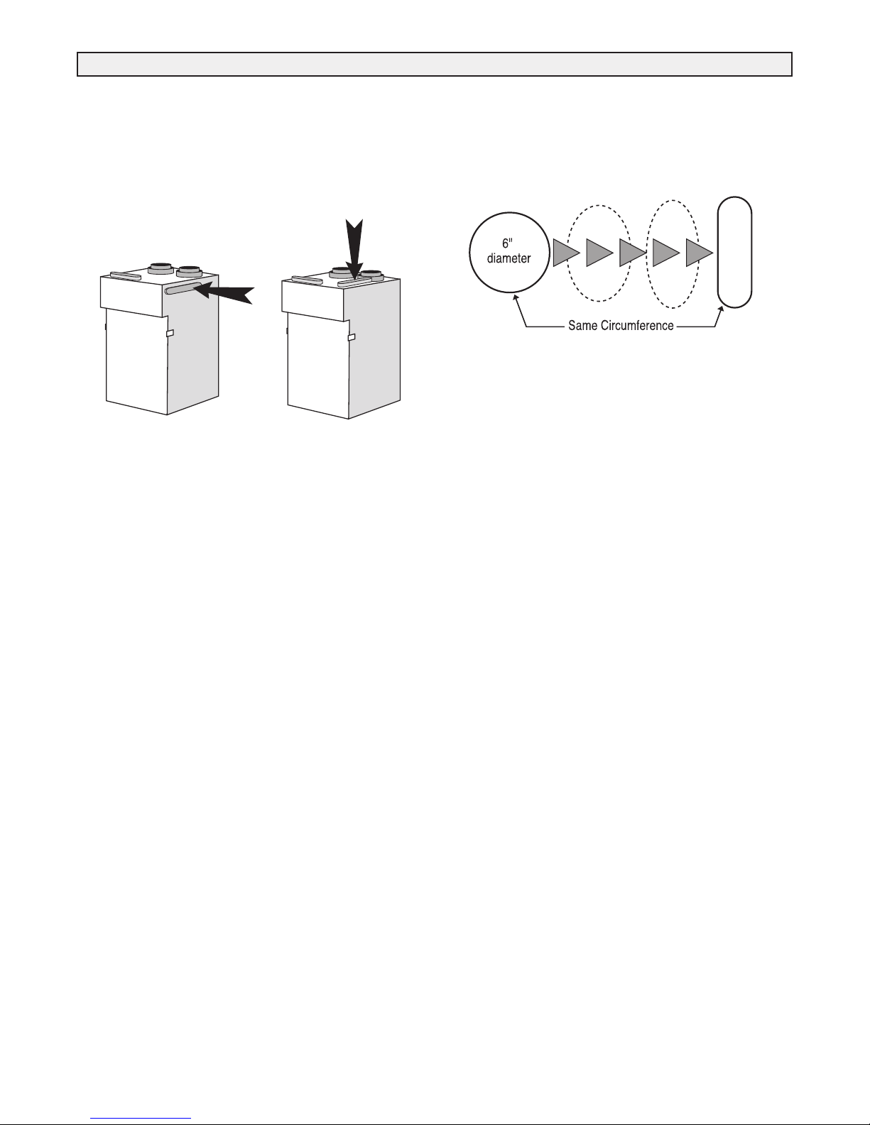
Port Configuration and Airflow Model 95MAX
95MAX Port Specifications
The 95MAX Heat Recovery Ventilator (HRV) has been designed
to allow the installer to choose between two possible positions on
the cabinet for the INDOOR EXHAUST (return from building)
port. Illustrations in this manual show standard (side mounted)
port location. The same specifications apply to both 95MAX
setups, regardless of which port position is selected.
SIDE MOUNTED PORT TOP MOUNTED PORT
standard location alternate location
Variable Port Location
Variable Port Location / Installation
(Model 95MAX only)
The exhaust return port collar is not factory installed. Installer
may choose either side mounted or alternate top mounted port by
simply removing one of the two knock-out plates and attaching a
port collar (supplied). To remove knock-out plate, insert a utility
knife into the knock-ou t slits and trace them completely to
puncture protective film underneath. Then, cut the solid tabs
between the slits, using tin snips or side cutters, and remove the
knock-out plate. If any protective film still blocks the opening,
remove it now.
In order to make the 95MAX as space efficient as possible, the
INDOOR supply and return ports are converted from round to oval
shape. Overall size of the port remains the same. Simply bend a
standard duct fitting to the correct shape, and attach to the oval
port using the same method as for a round port.
Round port bent to oval
95MAX Air Flow
Stale air enters the FRONT RIGHT side port. The air will pass
down the front half of the core, then up the back half of the core
and out the RIGHT REAR port.
Fresh outdoor air will enter the LEFT REAR port and pass down
the back half of the core. It will then pass up the front half of the
core, and out the LEFT FRONT port. This unique configuration
allows the air to actually travel through the core twice, making the
95MAX almost as efficient as a double core unit.
9
ENGINEERING DATA
info@lifebreath.com
5
1
2
3
4
20
40
60
80
100
120
140
160
0 0.1 0.2 0. 3 0.4 0.5 0.6 0.7
Static Pressure (in w.g.)
Air Flow (cfm)
5
- High Speed
*4 - Medium High S peed
*3 - Medium Speed
*2 - Medium Low Speed
*1 - Low speed
* Manufacturers Data
BAL ANCI NG DAM PER
33 5/8"
(850mm)
STALE AIR
FROM INSIDE
FRESH AIR
FROM OUTSIDE
STALE AIR
TO OUTSIDE
FRESH AIR
TO INSIDE
14 3/4"
(375)
19"
(48 3)
*Al l Duct C onne ctio ns 6" ( 150m m)
CON DENS ATE DRA INS
FILT ERS
BLO WERS
*NOT E: Fron t cle aranc e of 25 i nche s (63 5 mm)
is r ecom mende d for s ervi cing u nit.
REC IRCU LATIN G
DEF ROST
DAM PER
MOTO R
COR E
BAL ANCI NG DAM PER
THERMALLY CONDUCTIVE, PATENTED ALUMINUM CORE
The cross-flow heat recovery core transfers heat between the two airstreams. It is easily removed
for cleaning or service.
MOTORS AND BLOWERS
Each air stream has one centrifugal blower driven by a common PSC motor. 5 speed fan operation.
FILTERS
Washable air filters in exhaust and supply air streams.
MOUNTING THE HRV
Four threaded inserts at corners of the cabinet designed to accept the “S” hooks and hanging straps
supplied with the unit.
DEFROST
Recirculating damper defrost system.
CASE
Twenty gauge prepainted galvanized steel (G60) for superior corrosion resistance. Insulated to
prevent exterior condensation. Drain connections 2 - 1/2" (12 mm) OD. Balancing ports are
located in the door.
WEIGHT 71 lbs. (32.3 kg) SHIPPING WEIGHT 73 lbs. (33.2 kg)
CONTROLS & ELECTRONICS
The Lifestyle MAX Digital Control (included with unit) can be wall mounted in a central location
of the home. (3 wire) 20 gauge wire (min.) 100' length
Electronic features include:
• 5 Speed Operation on each mode
• 4 user selectable operational modes: Continuous Ventilation, 20 ON/40 OFF,
20 ON/40 Recirculation, Continuous Recirculation
• Humidity Control through dehumidistat
• Adjustable Dehumidistat function built into the main wall control
• Built-in Relay for Interfacing to furnace
OPTIONAL PROGRAMMABLE CONTROL
99-LS-01 Lifestyle MAX Programmable Control - contains all the features of the Lifestyle
MAX Digital Control with 7/24 programmable ventilation, (3 wire) 20 gauge wire
(min.) 100' length
OPTIONAL TIMERS
99-DET01 Lifestyle 20/40/60 Minute Timer - Initiates high speed ventilation for 20, 40, or 60
minutes, (3 wire) 20 gauge wire (min.) 100' length
99-20M01 Lifestyle 20 Minute Timer - Initiates high speed ventilation for 20 minutes,
(3 wire) 20 gauge wire (min.) 100’ length.
99-101 Mechanical Timer - Initiates High speed ventilation for up to 60 minutes,
(2 wire) 20 gauge wire (min.) 100' length
OPTIONAL ACCESSORIES
99-DH-01 Lifestyle Dehumidistat - Initiates high speed ventilation when the indoor humidity
level is above the set point. (3 wire) 20 gauge wire (min.) 100' length
99-163 Duct Heater w/ Electronic SCR Thermostat, 1 Kw, 6” (150 mm)
99-186 Weatherhoods, Two - 6” (150 mm) c/w 1/4” (6 mm) mesh screen
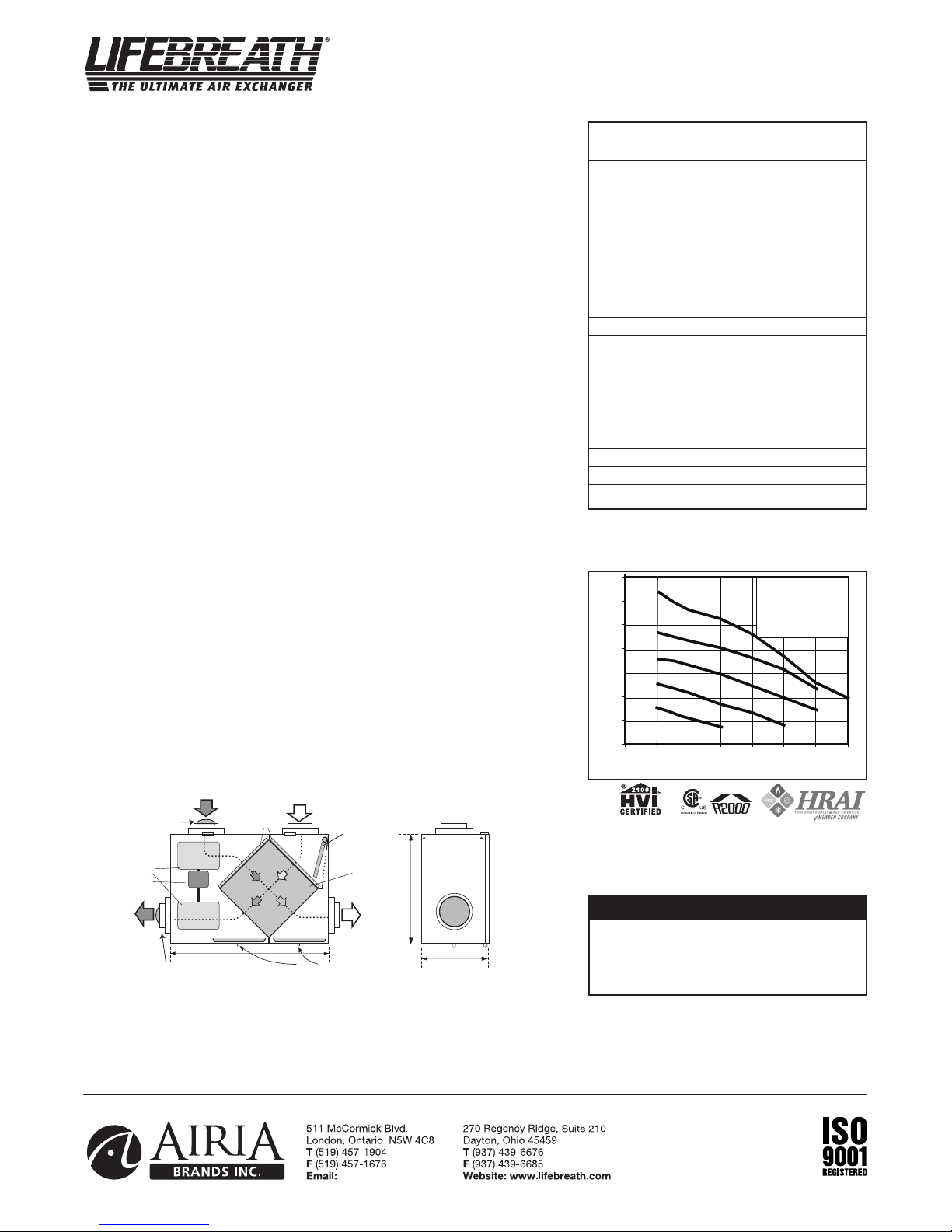
DIMENSIONS 155MAX inches (mm)
Model 155MAX
Performance (HVI certified)
Net supply air flow in cfm (L/s) against external static pressure
external static pressure) [cfm (L/s)]
(
Max. Temperature Recovery 78%
Sensible Effectiveness
@
*Sensible Efficiency
@ 65 cfm (31 L/s) 32°F (0°C) 64%
*Sensible Efficiency
@ 68 cfm (32 L/s) -13°F (-25°C) 66%
VAC @ 60HZ 120
WATTS / Low speed. 84
WATTS / High speed 117
Amp rating 1.4
*Sensible Efficiency – thermal **Latent Efficiency – moisture
ote: Effectiveness - based on temp. differential between the 2 airstreams
Efficiency – takes into account all power inputs
E.S.P
0.1" (25 Pa) 144 (68)
@
0.2" (50 Pa) 134 (63)
@
@ 0.3" (75 Pa) 125 (59)
@ 0.4" (100 Pa) 113 (53)
0.5" (125 Pa) 92 (43)
@
@ 0.6" (150 Pa) 73 (34)
65 cfm (31 L/s) 32°F (0°C) 73%
Date: ___________________________________________
Tag: _____________________Qty:___________________
Project: _________________________________________
Engineer: _______________________________________
All units conform to CSA and UL standards.
WARRANTY
Units carry a LIFETIME warranty on the heat recovery core and a 5
year replacement parts warranty.
Contractor: ______________________________________
Supplier: ________________________________________
Quote#: _________________________________________
Submitted by: ____________________________________
10
ENGINEERING DATA
14 3/4"
(375)
19"
(48 3)
*Al l Duct C onne ctio ns 6" ( 150m m)
*NOT E: Fron t cle aranc e
of 2 5 inch es (63 5 mm)
is r ecom mende d
for s ervi cing unit .
BAL ANCI NG DAM PER
33 5/8"
(850mm)
STALE AIR
FROM INSIDE
FRESH AIR
FROM OUTSIDE
STALE AIR
TO OUTSIDE
FRESH AIR
TO INSIDE
CON DENS ATE DRA INS
FILT ERS
BLO WERS
REC IRCU LATING
DEF ROST
DAM PER
MOTO R
COR E
BAL ANCI NG DAM PER
info@lifebreath.com
5
1
2
3
4
20
40
60
80
100
120
140
160
0 0.1 0.2 0. 3 0.4 0.5 0.6 0.7
Static Pressure (in w.g.)
Air Flow (cfm)
5 - High Speed
*
4 - Medium High Speed
*3 - Medium Speed
*2 - Medium Low Speed
*
1 - Low speed
* Manufacturers Data
THERMALLY CONDUCTIVE, PATENTED ALUMINUM CORE
The cross-flow heat recovery core transfers heat between the two airstreams. It is easily removed
for cleaning or service.
MOTORS AND BLOWERS
Each air stream has one centrifugal blower driven by a common PSC motor. 5 speed fan operation.
FILTERS
Washable air filters in exhaust and supply air streams.
MOUNTING THE HRV
Four threaded inserts at corners of the cabinet designed to accept the “S” hooks and hanging straps
supplied with the unit.
DEFROST
Recirculating damper defrost system.
CASE
Twenty gauge prepainted galvanized steel (G60) for superior corrosion resistance. Insulated to
prevent exterior condensation. Drain connections 2 - 1/2" (12 mm) OD. Balancing ports are
located in the door.
WEIGHT 71 lbs. (32.3kg) SHIPPING WEIGHT 73 lbs. (33.2 kg)
CONTROLS & ELECTRONICS
The Lifestyle MAX Digital Control (included with unit) can be wall mounted in a central location
of the home. (3 wire) 20 gauge wire (min.) 100' length
Electronic features include:
• 5 Speed Operation on each mode
• 4 user selectable operational modes: Continuous Ventilation, 20 ON/40 OFF,
20 ON/40 Recirculation, Continuous Recirculation
• Humidity Control through dehumidistat
• Adjustable Dehumidistat function built into the main wall control
• Built-in Relay for Interfacing to furnace
OPTIONAL PROGRAMMABLE CONTROL
99-LS-01 Lifestyle MAX Programmable Control - contains all the features of the Lifestyle
MAX Digital Control with 7/24 programmable ventilation, (3 wire) 20 gauge wire
(min.) 100' length
OPTIONAL TIMERS
99-DET01 Lifestyle 20/40/60 Minute Timer - Initiates high speed ventilation for 20, 40, or 60
minutes, (3 wire) 20 gauge wire (min.) 100' length
99-20M01 Lifestyle 20 Minute Timer - Initiates high speed ventilation for 20 minutes,
(3 wire) 20 gauge wire (min.) 100’ length.
99-101 Mechanical Timer - Initiates High speed ventilation for up to 60 minutes,
(2 wire) 20 gauge wire (min.) 100' length
OPTIONAL ACCESSORIES
99-DH-01 Lifestyle Dehumidistat - Initiates high speed ventilation when the indoor humidity
level is above the set point. (3 wire) 20 gauge wire (min.) 100' length
99-163 Duct Heater w/ Electronic SCR Thermostat, 1 Kw, 6” (150 mm)
99-186 Weatherhoods, Two - 6” (150 mm) c/w 1/4” (6 mm) mesh screen
DIMENSIONS 155MAX RX inches (mm)
Model 155MAX RX
(Weatherhood ports are on the right side of unit)
Net supply air flow in cfm (L/s) against external static pressure
(external static pressure) [cfm (L/s)]
0.1" (25 Pa) 144 (68)
@
@ 0.2" (50 Pa) 134 (63)
@ 0.3" (75 Pa) 125 (59)
0.4" (100 Pa) 113 (53)
@
@ 0.5" (125 Pa) 92 (43)
@ 0.6" (150 Pa) 73 (34)
Max. Temperature Recovery 78%
Sensible Effectiveness
@ 65 cfm (31 L/s) 32°F (0°C) 73%
*Sensible Efficiency
@ 65 cfm (31 L/s) 32°F (0°C) 64%
*Sensible Efficiency
@ 68 cfm (32 L/s) -13°F (-25°C) 66%
VAC @ 60HZ 120
WATTS / Low speed. 84
ATTS / High speed 117
W
mp rating 1.4
A
*Sensible Efficiency – thermal **Latent Efficiency – moisture
ote: Effectiveness - based on temp. differential between the 2 airstreams
Efficiency – takes into account all power inputs
Performance
.S.P
E
Date: ___________________________________________
Tag: _____________________Qty:___________________
Project: _________________________________________
Engineer: _______________________________________
All units conform to CSA and UL standards.
WARRANTY
Units carry a LIFETIME warranty on the heat recovery
core and a 5 year replacement parts warranty.
NOTE
Th is RX mo de l is rev er se fl ow wh ic h
means the cold sid e duc ti ng to th e
weatherhoods is located on the right side
of the unit.
Contractor: ______________________________________
Supplier: ________________________________________
Quote#: _________________________________________
Submitted by: ____________________________________
11
 Loading...