

Page 1
CLEAN • FRESH • AIR
OPERATION AND
INSTALLATION MANUAL
Contains
ControlAir 15
®
For Models:
200ERV
200ERVD
500ERV
700ERV
1200ERV
TO BE COMPLETED BY CONTRACTOR AFTER INSTALLATION
ControlAir 15
ControlAir 15
ControlAir 15
Analog Controls
Analog Controls
Installing Contractor
Telephone / Contact
CAUTION
Before
given to how the system will operate if connected to
any other piece of mechanical equipment, i.e. a forced
air furnace or air handler, operating at a higher static.
After
equipment must be confirmed, by measuring the
airflow’s of the Energy Recovery Ventilator (ERV), by
using the balancing procedure in this manual
It is always important to assess how the operation of
any Energy Recovery Ventilator may interact with
vented combustion equipment (ie. Gas Furnaces, Oil
Furnaces, Wood Stoves, etc.)
NEVER install an Energy Recovery Ventilator in a situation where its normal operation, lack of operation or
partial failure may result in the backdrafting or improper
functioning of vented combustion equipment!!!
IMPORTANT - PLEASE READ THIS
MANUAL BEFORE INSTALLING UNIT
installation, careful consideration must be
installation, the compatibility of the two pieces of
Serial Number
Installation Date Model
* LEAVE FOR HOMEOWNER
NOTE: Due to ongoing research and product development, specifications,
ratings and dimensions are subject to change without notice.
TI-83C-NE
0007
Page 2

TABLE OF CONTENTS
Warranty ..................................................................................... 2
ERV Questions and Answers ..................................................... 3
Select the Correct Size ERV .......................................................5
Specifications
Model 200ERV ........................................................................... 6
200ERVD ........................................................................ 7
500ERV ........................................................................... 8
700ERV ........................................................................... 9
1200ERV ........................................................................ 10
Description of your ERV
Part 1: Function and Control
Operation of the ControlAir 15 ................................................. 12
Glossary
Optional Remote Controls ......................................................14
m
.........................
Part 2: Installation
Installation
m • Location
• Mounting the ERV
• Electrical
Installing Air Ducts
• Outside Weatherhoods
• Locating the Weatherhoods
Installing Ducting from Weatherhoods to the ERV
•
• Ducting
• Connections to Furnace Ductwork ................................... 18
• Damper and Grilles ......................................................... 18
Air Flow Balancing and Procedure
Installation Diagrams
General Installation
..............................................................................16
...........................................................11
......................
................................................................ 17
..................................................... 20 - 21
........................................................ 22 - 26
.................................. 12
...................................... 19
INTRODUCTION
The LIFEBREATH Enthalpic Core Energy
Recovery Ventilator (ERV) is designed for
warm, humid regions and it uses the vapour
transmission technology to transfer sensible
and latent heat to the cooler, drier air
stream. During the cooling season, humidity
drawn in from the outside is transferred
through the core to the exhaust air stream,
helping lower the load on the air conditioner.
It is recommended for regions where the
temperature does not drop below 25˚F (-4˚C).
WARRANTY
All LIFEBREATH Energy Recovery Ventilators
carry a five year warranty on the Energy Recovery
Core, Model 200ERV has a 5 year warranty on
replacement parts and Model 500, 700, and 1200
ERV has a 2 year warranty on replacement parts.
Maintenance
Troubleshooting Your ERV ...................................................... 27
Maintenance Routine ....................................
Wiring Diagram ..................
TFP Information ....................................................................... 32
..............................................
................
.......... 28
29 - 31
2
Page 3

ERV Questions & Answers
What is the difference between an HRV
and an ERV?
The core in an HRV (Heat Recovery Ventilator) transfers heat from one air stream to the other. This is called
sensible heat
Ventilator) is usually used to describe a unit with an
enthalpic core that transfers moisture as well as heat
from one air stream to the other. This (moisture transfer) is called
. The term ERV (Energy Recovery
latent heat
.
Enthalpic - what does it mean?
Enthalpy is the term used to describe the energy content of air. This energy is a combination of the sensible
and latent heat. Therefore, a core which transfers energy is called an enthalpic core.
Is an ERV better than an HRV?
NOT NECESSARILY!! In cold climates such as most of
North America, an HRV works better than an ERV. This
is because the air inside the home during the winter
months will be more humid than the outside air. An ERV
would transfer the latent heat (humidity) from the
exhaust air back into the incoming airstream. This will
aggravate moisture problems in the home and encourage the growth of mold and mildew. If the air in the
home is too dry for comfort, an ERV will not help. A
humidifier should be used to increase the humidity to a
comfortable level.
Where do you use an ERV instead
of an HRV?
An ERV is recommended for warm, humid areas with
heavy air conditioning use. As there is no defrost in an
ERV it is not recommended for areas where the temper-
ature drops below -4
˚C (25˚F)
Why transfer moisture in the summer
(cooling season)?
The enthalpic core will allow moisture to be transferred
from a humid air flow to a dry air flow. This property is
useful in the cooling season if an air conditioning system is used to lower the indoor humidity. You will then
have dry, cool air in the exhaust of the ERV, and warm
humid air in the supply stream. With these conditions,
the ERV will be able to transfer the moisture and heat of
the supply air to the exhaust air. In this way, the ERV
will supply to the home air which is cooler and drier than
outside. Remember that an ERV is not a dehumidifier,
and on its own will not take moisture out of the air.
damp situation. In fact, about 2/3 of the energy used by
the air conditioner system is to remove moisture.
Therefore, when ventilating in the summer, less moisture brought into the home means less work for the air
conditioner, and energy savings for you.
During the winter, an ERV recovers some humidity
from the exhaust air, reducing the need for humidification, if the required ventilation rate would make the
home too dry.
What's the difference between this type of
core and a rotary type?
Here's a list of characteristics of the fixed plate core.
1. No rotating parts, so maintenance is easy and the
unit lasts a long time.
2. It is very flexible in terms of installation.
3. The core can easily be changed.
4. Because the supply and exhaust air streams are
completely separate, there is very little cross leakage
of any dust or germs.
Can the core become clogged with dust?
Because the surface of the core is a turbulent flow
area, dust sticks to it easily; however, because the
inside of the element is a laminar flow area, virtually no
dust sticks to it.
What is the maintenance?
About once a year you should use a vacuum cleaner to
remove the dust from the core's surface. DO NOT
WASH WITH WATER!!
Is an air filter needed?
To prevent clogging of the core, an air filter should
always be installed on the supply and exhaust sides of
the core.
How much ventilation do I need?
During seasons when your windows and doors are
closed, the ERV should operate continuously when the
dwelling is occupied, and either continuously or intermittently when not occupied.
For most installations the ERV will normally be set to
operate continuously on low speed with the option of
going to high speed as the need arises. For example; if
you are entertaining and there is a large number of
people present (some may be smoking), the unit
should be switched to high speed.
So why use an ERV?
A properly operating air conditioner will not only lower
the temperature in your house, but will also lower the
humidity level. This prevents an uncomfortable cold and
Your ERV may be equipped with automatic or manual
switches, but all ERVs will have a manual speed control
override.
3
Page 4
CLEAN • FRESH • AIR
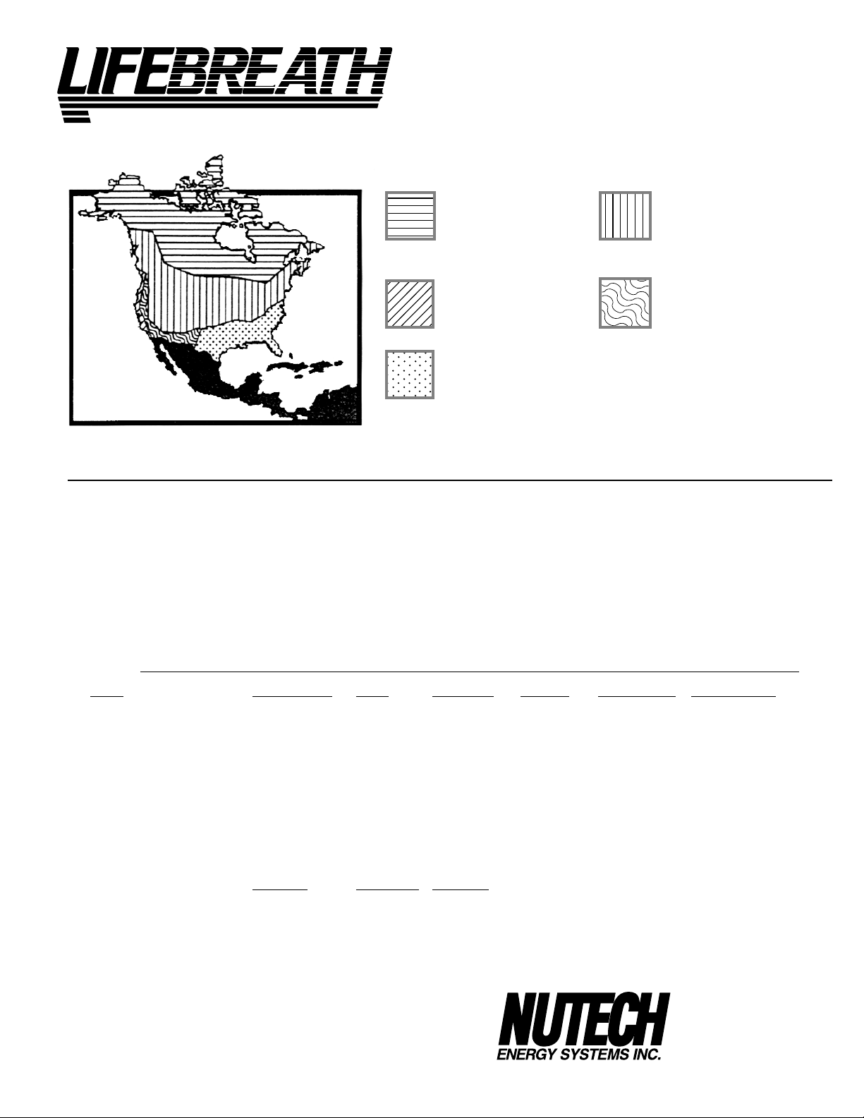
Select the correct Lifebreath to match your climate
®
Severe Conditions Moderate Conditions
HRV recommended HRV recommended
Double core high efficiency HRV
recommended for extreme conditions
Pacific Coastal Arid Zone-Dry Climate
HRV recommended HRV recommended
ERV optional* Double core high efficiency HRV optional
Extreme Area**-High Humidity
ERV recommended*
*ERV not recommended where temperatures fall below 25˚F (-4˚C) for more than 5 days.
**ERV 's are recommended in regions where high outdoor humidity is cause for operating air
conditioning/dehumidification more frequently than heating system.
The following table is used to outline total dollar ventilation costs for Heat Recovery Ventilators
(HRV's) and Energy Recovery Ventilators (ERV's) for various geographic regions in the United States and Canada.
Costs are for balanced systems using values based on electricity at $0.086 per kWh and fossil fuel at $0.72 per therm
(100, 000 BTU). It was assumed that electric heat was 100% efficient and fossil fuel heat was 80% efficient. Cooling
equipment had a SEER of 12.
Ventilation energy costs would include both fan energy use and the energy required to condition the air displaced by
the ventilation system.
Straight ventilation costs are also included to show the benefit of recovery.
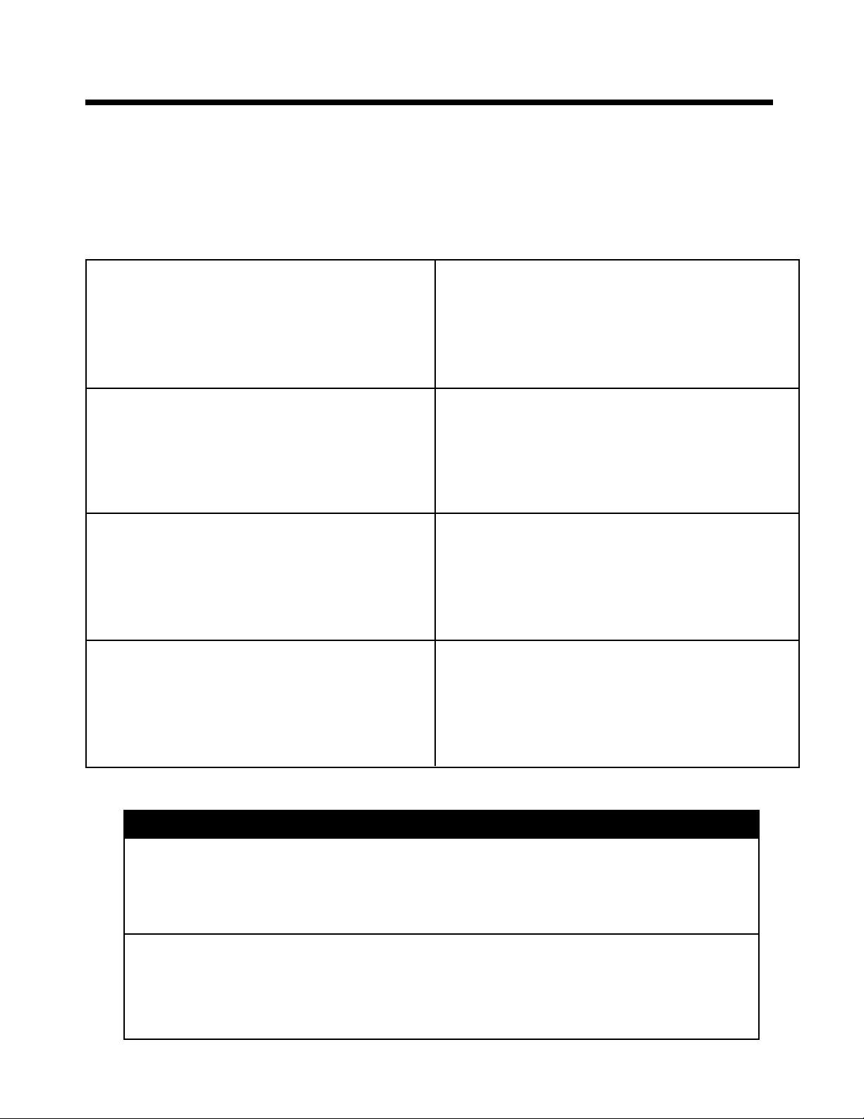
ANNUAL SAVINGS WITH BALANCED MECHANICAL VENTILATION WITH ENERGY RECOVERY
MODE LOS ANGELES MIAMI NEW YORK DETROIT MINNEAPOLIS PORTLAND, OR
HRV - ELECTRIC HEAT
ERV - ELECTRIC HEAT
HRV - FOSSIL FUEL HEAT $60.97 $124.95 $80.72 $81.73 $92.08 $66.19
ERV - FOSSIL FUEL HEAT $59.56 $104.42 $76.84 $79.37 $88.38 $65.76
VENTILATION ONLY-FOSSIL
VENTILATION ONLY-ELECTRIC
SAVINGS WITH ERV-ELECTRIC $69.86 $133.61 $179.89 $228.79 $285.22 $76.20
SAVINGS WITH HRV-ELECTRIC $65.05 $85.68 $192.65 $257.23 $322.46 $110.80
SAVINGS WITH ERV-FOSSIL $65.93 $150.51 $133.20 $156.36 $191.05 $103.28
SAVINGS WITH HRV-FOSSIL $64.52 $129.98 $129.32 $154.00 $187.35 $102.85
HRV - ELECTRIC HEAT $145.30 $155.04 $189.52
ERV - ELECTRIC HEAT $179.78 $196.74 $253.93
HRV - FOSSIL FUEL HEAT $82.72 $84.87 $93.49
ERV - FOSSIL FUEL HEAT $80.80 $83.27 $92.49
VENTILATION ONLY-FOSSIL
VENTILATION ONLY-ELECTRIC
SAVINGS WITH ERV-ELECTRIC $249.37 $276.87 $368.91
SAVINGS WITH HRV-ELECTRIC $283.85 $318.57 $433.32
SAVINGS WITH ERV-FOSSIL $166.60 $180.99 $230.41
SAVINGS WITH HRV-FOSSIL $164.68 $179.39 $229.41
$71.57 $171.66 $125.19 $138.83 $166.62 $142.18
$66.76 $123.73 $137.95 $167.27 $203.86 $176.78
$125.49 $254.93 $210.04 $253.73 $279.43 $169.04
$136.62 $257.34 $317.84 $396.06 $489.08 $252.98
TORONTO MONTREAL WINNIPEG
$247.40 $264.26 $322.90
$429.15 $473.61 $622.84
511 McCormick Blvd.
London, Ontario
Canada N5W 4C8
Phone: (519) 457-1904
Fax: (519) 457-1676
4
Page 5
Selecting the Correct Size ERV
Commercial and Institutional Requirements
For outdoor air requirements, ASHRAE has produced the Ventilation Standard 62-1989 that
is used to determine acceptable ventilation rates. This standard is referenced directly or
used as “Good Engineering Practice” in most Code documents or design criteria.
Small restaurants, Donut Shops and Fast food stores
Seats 40
Employees 5
Total 45
ASHRAE requirement 20 cfm (10L/s) per person
Ventilation required 45 x 20 = 900 cfm (450 L/s)
Bar or Tavern
Seats 50
Employees 7
Total 57
ASHRAE requirement 30 cfm (15L/s) per person
Ventilation required 57 x 30 = 1710 cfm (855 L/s)
Classroom and School Portables
Seats 29
Teacher 1
Total 30
ASHRAE requirement 15 cfm (7.5L/s) per person
Ventilation required 30 x 15 = 450 cfm (255 L/s)
Beauty Salon
Customers 12
Employees 6
Total 18
ASHRAE requirement 25 cfm (12.5L/s) per person
Ventilation required 18 x 25 = 450 cfm (255 L/s)
Bank
Customers 25
Staff 9
Total 34
ASHRAE requirement 20 cfm (10L/s) per person
Ventilation required 34 x 20 = 680 cfm (320 L/s)
Bingo Hall
Customers 180
Staff 20
Total 200
ASHRAE requirement 30 cfm (15L/s) per person
Ventilation required 200 x 30 = 6000 cfm (3000 L/s)
Print Shop, Duplicating
Square footage of shop 2000 square ft (m
ASHRAE requirement 0.5 cfm/ft2 (2.5L/s - m
per person
Ventilation required 2000 x 0.5 = 1000 cfm (500 L/s)
Swimming Pools
1 cfm per sq. ft. of the water surface area
or
0.5 cfm per sq. ft. of the water surface plus deck area
Hot Tubs
7 - 10 cfm per sq. ft. of the water surface area
2
)
2
)
MAKE UP HEAT REQUIREMENT at 1200 CFM (566L/s)
Nominal Nominal Nominal
Outdoor Temp. kW Req. for kW Req. for kW Req. for
C° F° 20°C (68°F) 25°C (77°F) 30°C (86°F)
Air Delivery Air Delivery Air Delivery
0 32 7 10 14
-10 14 10 14 17
-20 -4 12 15 19
-30 -22 15 19 22
-40 -40 17 21 24
5
Page 6
®
CLEAN • FRESH • AIR
ENGINEERING DATA
LATENT RECOVERY/MOISTURE TRANSFER CORE
The cross-flow energy recovery core transfers heat and water vapour
between the two airstreams. It is easily removed for cleaning or service.
MOTORS AND BLOWERS
driven by a common PCS motor. 5 speed fan operation.
High speed - 120 VAC, 1.4 Amps, 164 Watts.
FILTERS
- Washable air filters in exhaust and supply air streams.
MOUNTING THE ERV
corners of case designed to accept four PVC reinforced polyester straps
that are supplied with the unit.
CASE
- Twenty gauge prepainted galvanized steel (G60) for superior
corrosion resistance. Insulated to prevent exterior condensation.
CONTROLS
WEIGHT
- ControlAir 15
63 lbs. (28.7 kg)
-
Each air streams has one centrifugal blower
- Four 10/24" (10.5 mm) threaded inserts at
SHIPPING WEIGHT
65 lbs. (29.6 kg )
Model 200 ERV
PERFORMANCE
Net supply airflow in cfm (L/s) against external static pressure
E.S.P cfm L/s
@ 0.1” (25 Pa) 195 (92)
@ 0.2” (50 Pa) 185 (87)
@ 0.3” (75 Pa) 175 (83)
@ 0.4” (100 Pa) 160 (76)
@ 0.5” (125 Pa) 145 (68)
Sensible Effectiveness
@ 110 L/s (55 cfm)
Sensible Efficiency
@ 110L/s (55 cfm) @0
Sensible Efficiency
@ 110 L/s (55 cfm) @ -25
VAC @ 60HZ 120
WATTS / Low speed 80
Amp rating 1.4
HVI CERTIFIED
(CSA C439M)
O
C (32°F) 70%
O
C (-13°F)
80%
55%
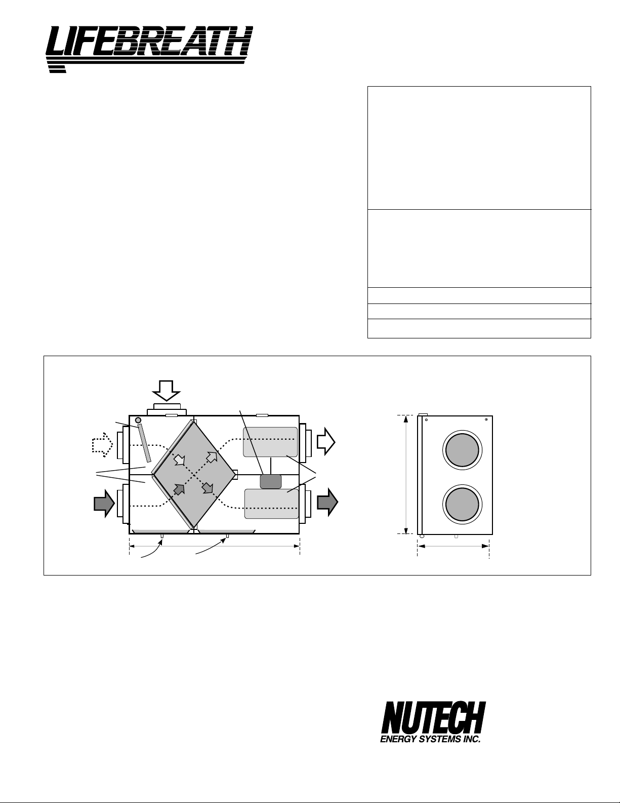
DIMENSIONS 200 ERV
*
All Duct Connections 6"(150mm)
STALE AIR
FROM INSIDE
FILTERS
FRESH AIR
FROM OUTSIDE
OPTIONS
99-104 Digital Electronic Timer - 20/40/60 min. (3 wire)
99-105 Deluxe Programmable Control includes
Programmable Time Clock, Dehumidistat
and Air Sentry™
99-109 Air Sentry™ Air Quality Monitor
99-186 Weatherhoods, Two - 6” (150mm)
c/w 1/4” (6mm) mesh screen
MOTOR
31"
(787)
inches (mm)
FRESH AIR
TO INSIDE
BLOWERS
STALE AIR
TO OUTSIDE
19"
(483)
14 3/4"
(375)
*NOTE: Front clearance
of 25 inches (635 mm)
is recommended
for servicing unit.
WARRANTY
Units carry a 5 year warranty on the energy recovery core and
replacement parts.
All units are CSA and UL standards.
It is not recommended for regions where the temperature
does not drop below 25°F (-4°C)
DATE: __________________________
PROJECT: ___________________________________
MECHANICAL CONTRACTOR: __________________________
6
511 McCormick Blvd.
London, ON N5W 4C8
Phone: (519) 457-1904
Fax: (519) 457-1676
Email: nutech@lifebreath.com
TI-98E
0006
Page 7
®
CLEAN • FRESH • AIR
ENGINEERING DATA
LATENT RECOVERY/MOISTURE TRANSFER CORE
The cross-flow energy recovery core transfers heat and water vapour
between the two airstreams. It is easily removed for cleaning or service.
MOTORS AND BLOWERS
driven by a common PCS motor. 5 speed fan operation.
High speed - 120 VAC, 1.4 Amps, 164 Watts.
FILTERS
- Washable air filters in exhaust and supply air streams.
MOUNTING THE ERV
corners of case designed to accept four PVC reinforced polyester straps
that are supplied with the unit.
DEFROST
CASE
- Damper defrost system.
- Twenty gauge prepainted galvanized steel (G60) for superior
corrosion resistance. Insulated to prevent exterior condensation.
DRAIN CONNECTIONS
CONTROLS
WEIGHT
- ControlAir 15
63 lbs. (28.7 kg)
-
Each air streams has one centrifugal blower
- Four 10/24" (10.5 mm) threaded inserts at
- Two - 1/2” (12mm) O.D.
SHIPPING WEIGHT
65 lbs. (29.6 kg )
Model 200 ERVD
PERFORMANCE
Net supply airflow in cfm (L/s) against external static pressure
E.S.P cfm L/s
@ 0.1” (25 Pa) 195 (92)
@ 0.2” (50 Pa) 185 (87)
@ 0.3” (75 Pa) 175 (83)
@ 0.4” (100 Pa) 160 (76)
@ 0.5” (125 Pa) 145 (68)
Sensible Effectiveness
@ 110 L/s (55 cfm)
Sensible Efficiency
@ 110L/s (55 cfm) @0
Sensible Efficiency
@ 110 L/s (55 cfm) @ -25
VAC @ 60HZ 120
WATTS / Low speed 80
Amp rating 1.4
HVI CERTIFIED
(CSA C439M)
O
C (32°F) 70%
O
C (-13°F)
80%
55%
FRESH AIR
FROM OUTSIDE
DAMPER
DEFROST
PORT
FILTERS
STALE AIR
FROM HOUSE
CONDENSATE DRAINS
DIMENSIONS 200 ERVD
*
All Duct Connections 6"(150mm)
MOTOR
31"
(787)
OPTIONS
99-104 Digital Electronic Timer - 20/40/60 min. (3 wire)
99-105 Deluxe Programmable Control includes
Programmable Time Clock, Dehumidistat
and Air Sentry™
99-109 Air Sentry™ Air Quality Monitor
99-186 Weatherhoods, Two - 6” (150mm)
c/w 1/4” (6mm) mesh screen
inches (mm)
STALE AIR
TO OUTSIDE
BLOWERS
FRESH AIR
TO INSIDE
19"
(483)
14 3/4"
(375)
*NOTE: Front clearance
of 25 inches (635 mm)
is recommended
for servicing unit.
WARRANTY
Units carry a 5 year warranty on the energy recovery core and
replacement parts.
All units are CSA and UL standards.
It is not recommended for regions where the temperature
does not drop below 25°F (-4°C)
DATE: __________________________
PROJECT: ___________________________________
MECHANICAL CONTRACTOR: __________________________
7
511 McCormick Blvd.
London, ON N5W 4C8
Phone: (519) 457-1904
Fax: (519) 457-1676
Email: nutech@lifebreath.com
TI-200ERVD
0006
Page 8
SPECIFICATIONS
CLEAN • FRESH • AIR
PERFORMANCE
®
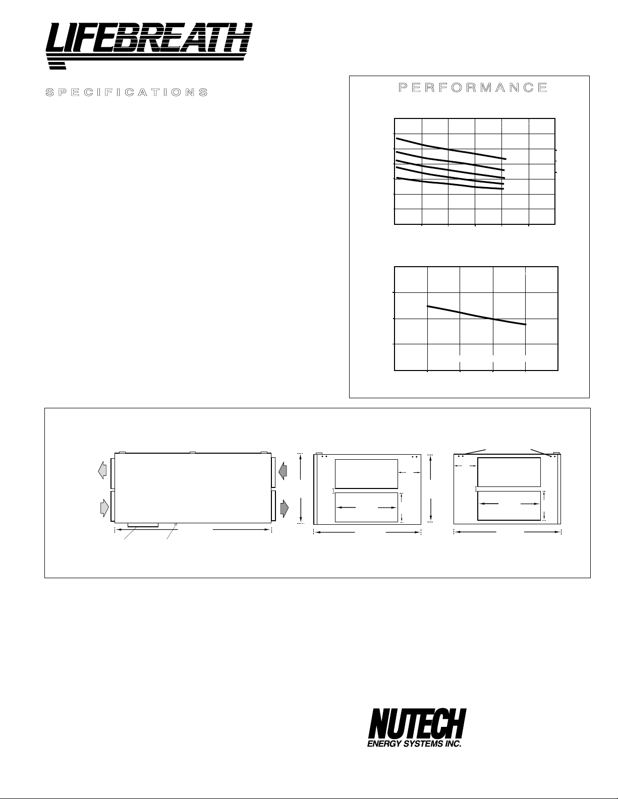
Model 500ERV
LATENT RECOVERY (MOISTURE) TRANSFER CORES
Modular (4 section) 2- Enthalpic, 2 Aluminum arranged for high
efficiency crossflow ventilation.
MOTORS
total on high speed). HP - 1/10, 1625 RPM. Watts - total on High Speed - 610.
FILTERS
BLOWERS
Each air stream has two centrifugal blowers driven by two PSC motors.
CONNECTION DUCT SIZES
MOUNTING
type apparatus (brackets and rods not included).
DEFROST
CASE
resistance. Insulated with foil faced insulation duct liner where required to
prevent exterior condensation. Drain connection, One - 1/2" (12 mm) O.D.
CONTROLS
WEIGHT
-
Two PSC, 5 speed double shafted, 120 VAC, 3.15 Amps each (6.3
- Washable air filters in exhaust and supply air streams.
- Centrifugal type rated at 530 cfm (250 L/s) free air delivery.
Four - 14" x 8" (356 mm x 200 mm).
- Unit to be set on support brackets hung by threaded rod
- Damper defrost system.
- 20 gauge prepainted galvanized steel (G60) for superior corrosion
- ControlAir 15
178 lbs. (81 kg)
SHIPPING WEIGHT
203 lbs. (92 kg)
AIRFLOWS (Each Air Stream)
282 (600)
235 (500)
190 (400)
143 (300)
94 (200)
AIRFLOW L/s (CFM)
42 (100)
25 (.1) 50 (.2) 75 (.3) 100 (.4) 125 (.5)
EXTERNAL STATIC PRESSURE IN PASCALS (in. W.C.)
TEMPERATURE EFFECTIVENESS
100%
90%
EFFECTIVENESS
80%
94
(200)
143
(300)
AIRFLOW IN L/s (CFM)
LIFEBREATH 500
SPEED
5
4
3
2
1
LIFEBREATH 500
NOTE: Exhaust Relative Humidity (RH) at 40%
190
(400)
235
(500)
6.3 HIGH
3.8 MED
3.1 LOW
282
(600)
TOTAL CURRENT DRAW (AMPS) @ 120 VAC
DIMENSIONS 500 ERV
EXHAUST AIR
TO OUTSIDE
NOTE:
Service clearance
is 30 in. (760 mm)
SUPPLY AIR
FROM OUTSIDE
DEFROST
DRAIN CONNECTION
49"
(1245 mm)
FRONT VIEW
OPTIONS
99-104 Digital Electronic Timer - 20/40/60 min. (3 wire)
99-105 Programmable Ventilation Control includes
Programmable Time Clock, Dehumidistat and
Air Sentry™
99-109 Air Sentry™ Air Quality Monitor
________________
DATE:
PROJECT:
________________________________________
MECHANICAL CONTRACTOR:
UNIT SELECTED:
__________________________
EXHAUST AIR
FROM BUILDING
SUPPLY AIR
TO BUILDING
_____________
18 3/4"
(475 mm)
8
inches (mm)
MOUNTING POINTS
5 7/8"
(150 mm)
1 3/8"
(35 mm)
EXTERIOR DUCT
14"
(356 mm)
28 1/4"
(717 mm)
CONNECTION SIDE
8"
(200 mm)
1 1/4"
(32 mm
)
14"
(356 mm)
28 1/4 "
(717 mm)
INTERIOR DUCT
CONNECTION SIDE
5 7/8"
(150 mm)
8"
(200 mm)
18 3/4"
(475 mm)
All units conform to CSA and UL standards.
WARRANTY
Units carry a 5 year warranty on the energy recovery cores and
15 years on aluminum cores. Two (2) year replacement parts
warranty.
It is recommended for regions where the temperature does
not drop below 25°F (-4°C).
511 McCormick Boulevard.
London, ON N5W 4C8
Phone: (519) 457-1904
Fax: (519) 457-1676
E mail:nutech@lifebreath.com
TI-130
0006
Page 9
®
SPECIFICATIONS
PERFORMANCE
CLEAN • FRESH • AIR
LATENT RECOVERY (MOISTURE) TRANSFER CORES
Modular (2 section) enthalpic (moisture) transfer cores arranged for
efficient cross-flow ventilation.
MOTORS
Two PSC, 3 speed single shafted, 120 VAC, 2.75 Amps each (5.5 total
on high speed). HP - 1/10, 1625 RPM. Watts - total on high speed - 648.
FILTERS
Washable air filters in exhaust and supply air streams.
BLOWERS
Centrifugal type rated at 700 CFM (329 L/s) free air delivery. Each air
stream has one single shafted motor driving a centrifugal blower.
CONNECTION DUCT SIZES
Four - 14" x 8" (356 mm x 200 mm)
MOUNTING
Unit to be set on support brackets hung by threaded rod type
apparatus (brackets and rods not provided).
CASE
20 gauge prepainted galvanized steel (G60) for superior corrosion
resistance. Insulated with foil faced insulation where required to prevent exterior condensation.
CONTROLS
Illuminated power switch, 3 speed blower control, low voltage (24
VAC) terminals for connection of remote controls.
WEIGHT
142 lbs (64.4 kg)
SHIPPING WEIGHT
167 lbs. (75.8 kg)
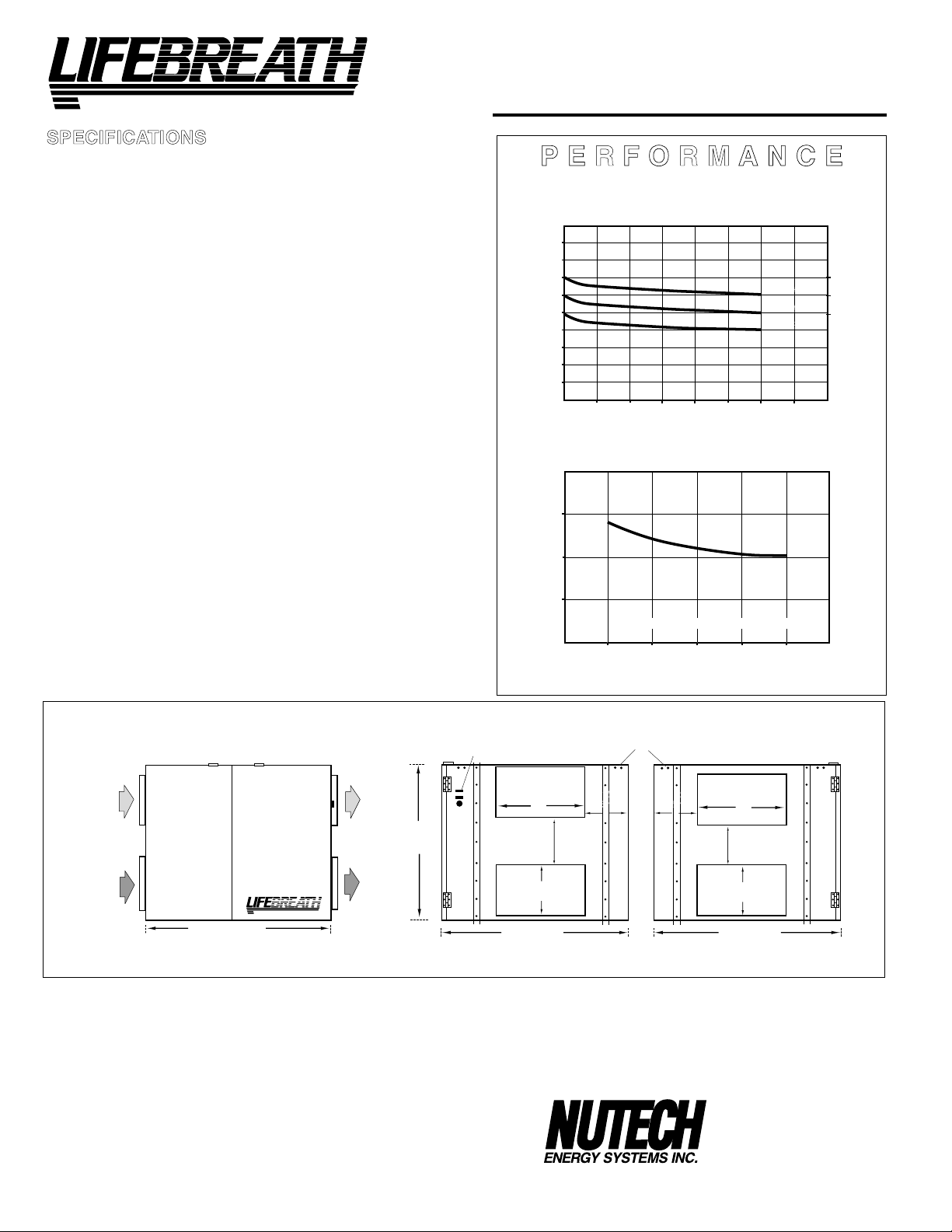
Model 700ERV
MODEL 700FD, 700DD
AIRFLOWS (Each Air Stream)
423 (900)
378 (800)
329 (700)
282 (600)
235 (500)
190 (400)
143 (300)
94 (200)
AIRFLOW L/s (CFM)
42 (100)
25 (.1) 50 (.2) 75 (.3) 100 (.4) 125 (.5) 150 (.6) 175 (.7)
EXTERNAL STATIC PRESSURE IN PASCALS (IN. W.C.)
TEMPERATURE EFFECTIVENESS
70%
60%
50%
EFFECTIVENESS
NOTE: Exhaust Relative Humidity (RH) at 40%
HIGH SPEED
MED SPEED
LOW SPEED
5.5 HIGH
5.0 MED
4.7 LOW
TOTAL CURRENT DRAW (AMPS) @ 120 VAC
DIMENSIONS 700
SUPPLY AIR
FROM OUTSIDE
NOTE:
Service clearance
is 30 in. (760 mm)
EXHAUST AIR
FROM BUILDING
HEAT RECOVERY VENTILATORS (HRVs)
29 5/8" (753 mm)
FRONT VIEW
All units conform to CSA and UL standards.
WARRANTY
Units carry a 5 year warranty on the energy recovery cores and
2 year replacement parts warranty.
DATE:
PROJECT:
MECHANICAL CONTRACTOR:
_________________________________________
______________________________________
__________________________
EXHAUST AIR
TO OUTSIDE
®
SUPPLY AIR
TO BUILDING
625 mm
(24 5/8 ")
190
inches (mm)
CONTROLS
14"
(356 mm)
8"
(200 mm)
28 3/4"
(730 mm)
DISCHARGE SIDE
8 1/4"
(210 mm)
(165 mm)
143
(400)
(300)
AIRFLOW IN L/s (CFM)
MOUNTING POINTS
6 1/2"
6 1/2"
(165 mm)
235
(500)
282
(600)
14"
(356 mm)
6 1/4"
(159 mm)
8"
(200 mm)
28 3/4"
(730 mm)
INLET SIDE
It is recommended for regions where the temperature
does not fall below 25°F (-4°C).
511 McCormick Blvd.
London, ON N5W 4C8
Phone: (519) 457-1904
Fax: (519) 457-1676
E mail: nutech@lifebreath .com
9
329
(700˚)
TI-131
9807
Page 10
CLEAN • FRESH • AIR
SPECIFICATIONS
PERFORMANCE
®
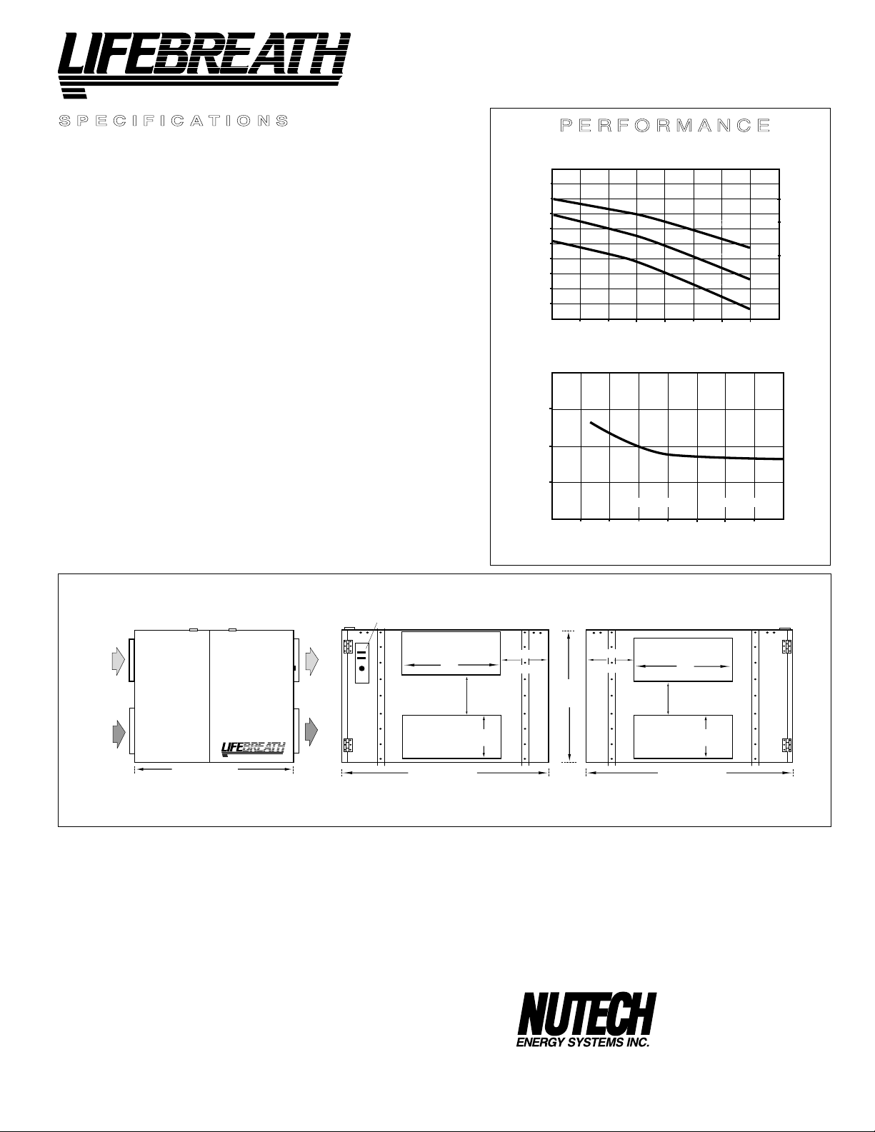
Model 1200ERV
LATENT RECOVERY (MOISTURE) TRANSFER CORES
Modular (3 section) latent recovery (moisture) transfer cores arranged for
efficient cross-flow ventilation.
MOTORS
Two PSC, 3 speed double shafted, 120 VAC, 4 Amps each (8.1 total on high
speed). HP - 1/4, 1625 RPM. Watts - total on high speed - 972.
FILTERS
Washable air filters in exhaust and supply air streams.
BLOWERS
Centrifugal type rated at 1200 cfm (566 L/s) free air delivery. Each air
stream has one double shafted motor driving a centrifugal blower.
CONNECTION DUCT SIZES
Four - 20" x 8" (508 mm x 200 mm).
MOUNTING
Unit to be set on support brackets hung by threaded rod type apparatus.
(brackets and rod not provided).
CASE
20 gauge prepainted galvanized steel (G60) for superior corrosion
resistance. Insulated with foil faced insulation where required to prevent
exterior condensation.
CONTROLS
Illuminated power switch, 3 speed blower control, low voltage (24 VAC)
terminals for connection of remote controls.
WEIGHT
191 lbs. (87 kg)
SHIPPING WEIGHT
215 lbs. (98 kg)
613 (1300)
566 (1200)
518 (1100)
472 (1000)
423 (900)
378 (800)
329 (700)
AIRFLOW L/s (CFM)
282 (600)
235 (500)
25 (.1) 50 (.2) 75 (.3) 100 (.4) 125 (.5) 150 (.6) 175 (.7)
EXTERNAL STATIC PRESSURE IN PASCALS (in. W.C.)
TEMPERATURE EFFECTIVENESS
70%
60%
EFFECTIVENESS
50%
500
500
(235)
(235)
AIRFLOWS (Each Air Stream)
8.1 HIGH
1100
1100
(518)
(518)
7.8 MED
7.1 LOW
1200
1200
(566)
(566)
HIGH SPEED
MED SPEED
LOW SPEED
NOTE: Exhaust Relative Humidity (RH) at 40%
700
800
900
700
(329)
(329˚)
800
(378)
(378)
600
600
(282)
(282)
AIRFLOW IN L/s (CFM)
900
(423)
(423)
1000
1000
(472)
(472)
TOTAL CURRENT DRAW (AMPS) @ 120 VAC
DIMENSIONS 1200
SUPPLY AIR
FROM OUTSIDE
NOTE:
Service clearance
is 30 in. (760 mm)
from front
access doors.
EXHAUST AIR
FROM BUILDING
29 7/8" (759 mm)
FRONT VIEW
EXHAUST AIR
HEAT RECOVERY VENTILATORS (HRVs)
TO OUTSIDE
¤
SUPPLY AIR
TO BUILDING
OPTIONS
99-101 Sixty Minute Remote Timer
99-130 Remote Wall Mount Dehumidistat Control
24 VAC only, W (white) or B (beige)
________________
DATE:
PROJECT:
________________________________________
MECHANICAL CONTRACTOR:
UNIT SELECTED:
__________________________
CONTROLS
inches (mm)
20"
(508 mm)
6 3/4"
(172 mm)
8"
(200 mm)
41 1/2"
(1055 mm)
DISCHARGE SIDE
All units conform to CSA and UL standards.
WARRANTY
Units carry a 5 year warranty on the energy recovery cores and 2
year replacement parts warranty.
It is recommended for regions where the temperature does
not fall below 25°F (-4°C).
_____________
10 3/8"
(263 mm)
24 5/8 "
(625 mm)
10 3/8"
(263 mm)
20"
(508 mm)
5 7/8"
(159 mm)
8"
(200 mm)
41 1/2"
(1055 mm)
INLET SIDE
511 McCormick Boulevard
London, Ontario
Phone: (519) 457-1904
Fax: (519) 457-1676
E mail:nutech@lifebreath.com
10
TI-132
9807
Page 11

STALE AIR
FROM INSIDE
DIMENSIONS 200 ERV
*
All Duct Connections 6"(150mm)
MOTOR
FRESH AIR
TO INSIDE
inches (mm)
FILTERS
FRESH AIR
FROM OUTSIDE
31"
(787)
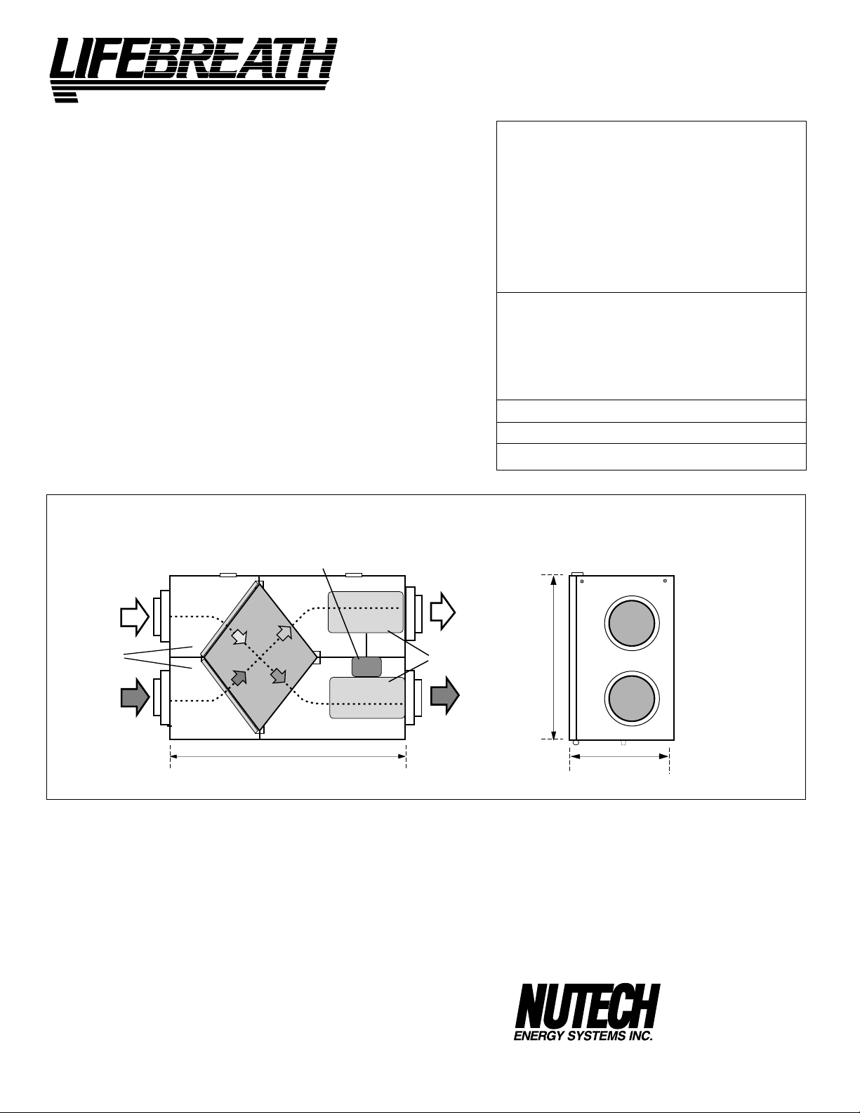
Figure 2
DESCRIPTION OF YOUR ERV
A) Air Circulation Fans and Motor
Inside the casing are two fans, one for exhaust air and one for
fresh air supply. Turning the fans is an efficient PSC motor.
B) Latent Recovery / Moisture Transfer Core
Cross-flow energy recovery core transfers heat and water
vapor between the two air streams, and is easily removed for
cleaning or service.
C) Air Filters
There are two permanent washable air filters. The filters lower
the amount of dust and outside particulates entering the Core
and your fresh air supply.
BLOWERS
STALE AIR
TO OUTSIDE
19"
(483)
14 3/4"
(375)
*NOTE: Front clearance
of 25 inches (635 mm)
is recommended
for servicing unit.
The Duct Ports
There are four duct ports on the ERV.
1) Fresh air intake port. It is connected to the exterior air intake hood using
insulated duct with a vapour barrier.
2) The fresh air supply port is connected to the fresh air diffuser, which
is typically located in the major living areas or connected to the return
of the HVAC forced air system.
3) Stale air return port is connected to exhaust grilles or the return of the
HVAC forced air system.
4) The exterior exhaust port is connected to the exterior exhaust hood
using insulated duct with vapour barrier.
Note:
The ERV is recommended for areas where the temperature
does not drop below 25˚F (-4˚C). The ERV does not require a
condensate drain, as the water vapour is either transmitted
through the exchanger core or is discharged outdoors.
11
Page 12

PART 1
FUNCTION & CONTROL
Models 200 & 500 Only
Operating the ControlAir 15
Plugging in the ERV energizes the unit. A self test function
will be performed every time the ERV is energized (refer to
“Self Test” for more details). After the self test has completed successfully the ERV will default to Speed 1. This is the
factory default setting. Follow the instructions found on the
ERV door to select desired mode and speed, or refer to the
instructions found on the following page.
Control Module
Control Pad
ControlAir 15
Exploded view
Self Test
Each time the ERV is powered/energized the self test function
will automatically initiate. During the self test the ERV will
cycle through all the speeds available (1-5), test the damper
motor operation and will default back to the previous
mode/speed selection, (factory default is Speed 1). Total self
test duration is approximately 1min 30 sec.
Automatic Defrost Operation
*Not on all Erv’s
The advanced technology of the digital microprocessor
automatically activates the defrost system only as it is
needed. To be an efficient heat recovery device, the ERV
must effectively provide for core defrost as well as providing
efficient heat exchange. As outdoor conditions cool, the
temperature sensor (thermistor) tracks the supply air temperature. The thermistor then sends its signal to the microprocessor (circuit board) which initiates only the defrost
cycle time required to clear the core. On recirculating
defrost models, the core is defrosted when the supply air
port is automatically blocked off and exhaust air is redirected back through the ERV. On damper defrost models, the
core is defrosted when the supply air port is automatically
blocked off and the warm air surrounding the ERV is drawn
in through the defrost port. The mode indicator will flash
RED during the defrost cycle. This dramatic advance makes
more energy available for recovery as the unit spends less
time in defrost mode. By optimizing the defrost cycle, the
ERV combines money saving performance with a well
designed and reliable control system.
Glossary
Removing and relocating the
Control Pad
The Control Pad can be removed and installed in a remote location (100’
wire length max). The Control Pad can be installed in a 2x4 box with a
“Decora” type cover plate or can be installed in the optional “Ventilation
Dehumidistat” When the Control Pad is installed in a remote location all
optional controls will still be wired to the Control Module on the ERV.
When remotely mounted on its own, the Control Pad is wired to the
Control Module by 3 wire (min. 20 gauge). When remotely mounted in the
Ventilation Dehumidistat, 4 wires are required (min. 20 gauge). Connect
the colour coded terminals from the Control Pad/Ventilation Dehumidistat
to the corresponding terminals on the Control Module.
12
DEFROST MODE (
during cold weather, the ERV will automatically cycle through its
defrost mode as needed.
ENERGY RECOVERY VENTILATOR (ERV) - a ventilation system
that recovers energy from exhaust air, also known as an air-to-air
exchanger.
RESET - whenever resetting of the ERV is required, simply disconnect the power for 30 seconds.
STANDBY MODE - the ERV is energized and waiting for fan operation to be initiated by a remote device or manual override.
THERMISTOR
electrical resistance in a known manner, as outdoor temperatures
fluctuate.
*Not on all Erv’s)
- the ERV's temperature sensor which measures
-to ensure reliable operation
Page 13

To select mode of operation for ControlAir 15
Press and hold the fan selection button on the Control Pad. After 5 seconds the control will begin
to cycle each mode holding each for 2 seconds. Release the button when the desired mode of
operation is reached.
Modes of Operation LED Indication
OFF
Standby / On S
20 On / 40 Off
Recirculation
*Note: Not available on all HRVs
No LED’s illuminated
operation.
teady Green LED and Yellow LED to indicate speed
will run at speed selected in ventilation mode. Standby mode is
indicated by no speed indicator illuminated. Optional remote
controls will override standby or selected speed into high speed.
Flashing Green LED and Yellow LED to indicate speed.
ERV will operate in ventilation mode at speed selected for
20 minutes and OFF for 40 minutes.
Steady Red LED and Yellow LED to indicate Speed.
will operate in recirculate mode at the selected speed. Optional
remote controls will override unit into high speed ventilate mode.
ERV is off, no controls will initiate
ERV
ERV
To select speed
Momentarily press fan selection button and release. ERV will move into next speed. OFF is indicated by no yellow LED illuminated. Speed 1 is the first yellow LED. Speed five is indicated by a
flashing speed 4 LED.
Automatic Defrost
During cold outdoor conditions the ERV will occasionally go into an automatic defrost function, which
will prevent ice from forming on the core. Defrost is indicated by a flashing Red LED indicator.
*
Not on all Erv’s
13
Page 14

ControlAir 15
NEW!
ControlAir 15
OPTIONAL REMOTE CONTROLS
Models 200 & 500 Only
PROGRAMMABLE VENTILATION CONTROLLER (PVC)
LOCATION: Hallway, kitchen, office
& work place
• Advanced digital remote.
• Digital dehumidistat.
• Full fan speed control.
AIR SENTRY™
•
Recirculation mode (on compatible HRVs).
•
• 7 day, 24 hour programmable timer.
• Digital display and status lights.
• 100' (30 m) maximum wire length .
PART NO. 99-105
Connects to RED, ORANGE, GREEN and YELLOW terminals.
*NOTE: This device is NOT compatible with the Air Sentry .
VENTILATION DEHUMIDISTAT
LOCATION: Central location in house.
• Dehumidistat activates high speed over-
VENTILATION
DEHUMIDISTAT
ride when humidity level in home
exceeds setting.
• Knockout designed to accept Control
Pad when remotely mounted, giving full
HRV functionality & control from remote
location.
(connect 1/unit only)
Air Quality Sensor built-in.
AIR SENTRY™ AIR QUALITY SENSOR
LOCATION: Kitchen, basement,
(connect 1/unit only).
AIR SENTRY
FAN SPEED INDICATOR
work place
TM
• Digital Air Quality Monitor.
• Status light indicates fan speed.
• Increases ventilation to remove
odours and contaminants.
• Among gases detected are
cigarette smoke and formaldehyde.
IGITAL
IR
UALITY
D
PART NO. 99-109
ENSOR
A
Q
S
• 100' (30 m) maximum wire length.
Connects to RED, GREEN and YELLOW terminals.
**NOTE:
This device is NOT compatible with the PVC.
Control Module
Control Pad
• All controls wire to
matching colour on
the Control Module.
• Control Pad can be
removed and mounted
in a remote location.
PART NO. 99-250
Connects to BLACK RED, GREEN and YELLOW terminals.
*Replaces 99-116 DVC & 99-230 VRD.
*Only compatible with ControlAir 15 electronics.
DIGITAL ELECTRONIC TIMER (DET)
LOCATION: Bathrooms & kitchen
Connect up to 8 on 300
•
If a PVC or Air Sentry is used, connect
•
up to 5 on 300
' wire max.
• Touch pad operation
• 20/40/60 minute status lights
• Compact wall mount unit
• Mounts in 2x4 box
Shown with “decora” cover plate
•
PART NO. 99-104
Connects to RED, GREEN and YELLOW terminals.
' (91 m) wire max
(99-107W)
•
Control Pad mounts
in a 2”x 4” box or can
be mounted in the
optional Ventilation
Dehumidistat.
• Full fan speed control.
•
Three Modes of Operation
- Standby/ON
- 20 ON / 40 OFF
-
Recirculation
(on compatible HRV’s)
*See individual control instructions for more details.
14
0005
Page 15

Speed Selection and Controls
Model 700 and 1200 ERV only
These models are equipped with a 3 speed control, low
medium and high, as well as a lighted on/off switch and a
4 screw terminal strip. The terminal strip can be used to
hook up any low voltage device which will then jump the
unit to high speed from whatever setting the speed control
was on. The terminal strip can also be wired to allow the
from high to low from a remote location. To wire the unit in
this configuration you would need two electrical on/off
switches to be installed at the remote location into a double gang electrical enclosure or side by side. One should
be labeled on/off and the other should be labeled
high/low.
unit to be turned off from a remote location as well as
ON
OFF
ON/OFF ONLY
LOW
HIGH
LOW/HIGH ONLY
SWITCHING FROM REMOTE LOCATION
*Supplied and Installed by Contractor*
ON
OFF
ON/OFF/LOW/HIGH
LOW
HIGH
COMMON
ON/OFF SWITCH
3 SPEED CONTROL
HIGH
ON/OFF
Optional Remote Controls
RED BLACK ORANGE
DEHUMIDISTAT VENTILATION
CONTROL (DVC)
PART NO. 99-116
•Turns ERV ON/OFF
• Dehumidistat increases
ventilation when required
DEHUMIDISTAT
PART NO. 99-130W
•Provides high speed
ventilation when humidity
level exceeds setting
Off
10
20
60
50
30
40
60 MINUTE CRANK TIMER
PART NO. 99-101
•Provides high speed
ventilation for 60 minutes
15
This style of remote switching began
approximately July 1997
Page 16

PAR T 2
INSTALLATION
Model 200 only
Location
The ERV must be located in a conditioned space where it
will be possible to conveniently service the unit. Typically
the ERV would be located in the mechanical room or an
area close to the outside wall where the weatherhoods
will be mounted. If a basement area is not convenient or
does not exist, a utility or laundry room may be used
Attic installations are not normally recommended due to:
A) the complexity of work to install
B) extreme temperatures in the attic
C) difficulty of access for service and cleaning
Sufficient clearance at the front of the access door is
required for servicing the air filters and core. A minimum
of 25" (635 mm) clearance is recommended so the door
can be opened. Four PVC reinforced polyester hanging
straps are provided for hanging the ERV from the basement floor joists.
Mounting
The hanging straps should be attached to the unit at the
top end corners (mounting screws are already located on
the ERV case). Securely fasten the other end of the straps
to the floor joists with wide head nails (not supplied), making sure the unit is level. The straps are designed to
reduce the possibility of noise, resonance or harmonics;
therefore using the full length of the strap between the
ERV and the floor joists is recommended.
WARNING:
In order to prevent electric shock when cleaning or servicing the ERV, it is extremely important to confirm the
polarity of the power line that is switched by the safety
(disconnect) switch. The hot line (black) is the proper line
to be switched. To confirm the proper polarity, use a voltmeter or test lamp to ensure there is no power after the
switch when the door is open. Check between that point
and ground (on the cabinet). This must be done as
dwellings are occasionally wired improperly. Always
make sure that the ERV is properly grounded.
Connecting Appliances to the ERV
It is not recommended that any of the following appliances be connected to the ERV:
Lint, dust or grease will collect in the ERV, damaging the unit.
• clothes dryer
• range top
• stovetop fan
• central vacuum system
Connecting any of these to the ERV will
invalidate your warranty.
Electrical
The ERV should be plugged into a standard designated
(120VAC) electrical outlet with ground. It is not recommended that an extension cord be used for this appliance.
If further wiring is required, then a licensed electrician
should make all electrical connections. It is recommended
that a separate 15 amp/120 volt circuit be used.
16
Page 17

INSTALLING AIR DUCTS
A well designed and installed ducting system will allow the
ERV to operate at its maximum efficiency.
Always try to keep duct runs as short and straight as
possible.
When installing the weatherhood, its outside perimeter
must be sealed with exterior caulking.
• At least 3' (1m) away from the corner of the building
• Not near a gas meter, electric meter or a walkway
where fog or ice could create a hazard
• Not into a garage, workshop or other unheated space
See Figures 6-9 for diagrams of various installations.
Outside Weatherhoods
The fixed covered hoods have a built-in bird screen with a
1/4" (6 mm) mesh to prevent foreign objects from entering
the ductwork.
Locating the Intake
Weatherhood
• Should be located upstream (if there are prevailing
winds) from the exhaust outlet
• At least 6' (2 m) from the exhaust weatherhood
• At least 6' (2 m) away from dryer vents and furnace
exhaust (medium or high efficiency furnaces)
• A minimum of at least 6' (2 m) from driveways, oil fill
pipes, gas meters, or garbage containers
• At least 18" (457 mm) above the ground,
or above the depth of expected snow accumulation
• At least 3' (1 m) from the corner of the building
• Do not locate in a garage, attic or crawl space
Installing the ducting from
the weatherhoods to the ERV
The inner and outer liners of the flexible insulated duct
must be clamped to the sleeve of the weatherhoods (as
close to the outside as possible) and the appropriate port
on the ERV. It is very important that the fresh air intake line
be given special attention to make sure it is well sealed. A
good bead of high quality caulking (preferably acoustical
sealant) will seal the inner flexible duct to both the ERV
port and the weatherhood prior to clamping.
To minimize air flow restriction, the flexible insulated duct
that connects the two outside weatherhoods to the ERV
should be stretched tightly and be as short as possible.
Twisting or folding the duct will severely restrict air flow. See
Figure 6 for the recommended connection of flexible insulated ducts to the the outside weatherhoods and the ERV.
Ducting
Locating the Exhaust
Weatherhood
• At least 6' (2 m) from the ventilation air intake
• At least 18" (457 mm) above ground or above the
depth of expected snow accumulation
WEATHERHOOD INSTALLATION
BELT OF OUTSIDE WALL
INSULATED FLEXIBLE
HOOD
BIRD
SCREEN
Figure 4
THERMAL COLLAR
1/ Thermal Collar slides over galvanized
sleeve of Weatherhood.
2/ Fasten Thermal Collar to Belt.
3/ Slide the Insulated Flexible Ducting over
the Weatherhood’s galvanized sleeve and
fasten it to the Thermal Collar.
4/ Hood is hinged to allow for easy access
for cleaning of bird screen.
DUCTING
To maximize airflow in the ductwork system, all ducts
should be kept short and have as few bends or elbows as
possible. Forty-five degree elbows are preferred to 90°
elbows. Use “Wye” (Y) fittings instead of "Tees" (T) whenever possible.
All duct joints must be fastened with screws, rivets or duct
sealant and wrapped with a quality duct tape to prevent
leakage. We recommend aluminum foil duct tape.
Galvanized ducting from the ERV to the living areas
in the house is recommended whenever possible, though
flexible duct can be used in moderation if so desired.
To avoid possible noise transfer through the ductwork system, a short length (approximately 12 " or 300 mm) of nonmetallic flexible insulated duct should be connected between
the ERV and the supply/ exhaust ductwork system.
The main supply and return lines connected to the ERV
must be the same diameter as the duct connections (or
larger for extensive duct runs). Branch lines to the individual rooms may be as small as 4 inches (100 mm), but 5
inch (125 mm) lines are preferred .
All ducts running through attics and unconditioned spaces
must be sealed and insulated to code.
17
Page 18

SUPPLY AIR DUCTING
In homes without a forced air furnace (see Fig. 7), fresh air should
be supplied to all bedrooms and living areas, excluding bathrooms, kitchen and utility areas. It should be supplied from high
wall or ceiling locations. Grilles that diffuse the air comfortably
such as the TECHGRILLE (Fig.5) are recommended.
If the floor is the only option available, then special care should be
taken in locating grilles. Areas such as under baseboard heaters
will help to temper the air. Also optional inline duct heaters are
available for mounting in the supply duct work to add heat if
required.
In homes with a forced air furnace, you may want to connect the
ERV to the furnace ductwork (see information below).
Dampers and Grilles
The use of balancing dampers and/or adjustable grilles to balance the flow rates into various rooms is recommended. We
suggest TECHGRILLE air diffusers available from NUTECH
(see Fig.5).
• The TECHGRILLE is a round, fully adjustable grille, which
provides superior, quiet air distribution.
• Available in 4", 5", 6" and 8" diam.(100,125,150 and 200 mm).
Direct Connection to Furnace Ductwork
Should you wish to hard duct the supply air directly into the cold
air return of the furnace (see Figures 7, 8, 9), remember to check
the air flow balance of the ERV with the furnace fan both "ON" and
"OFF" to determine that it does not imbalance the unit more than
10%. Also, it is advisable to include a short length of fabric flex
duct or other non-metallic connector in this hard ducted line in
order to keep the ERV separately grounded (electrically) from the
furnace. This will avoid a possible shock hazard to Service People
if a short to ground develops in one of the devices.
AIR FLOW
SUPPLY
Indirect Connection to Ductwork
If permitted by local codes, an indirect connection may be made
between the ERV supply duct and the return plenum of the HVAC
system. The fresh air from the unit may be directed at a grille
installed in the cold air return duct of the HVAC system. The fresh
air supply outlet from the unit should be no closer than 4 inches
(100 mm) and no more than 12 inches (300 mm) from the grille.
CAUTION: An indirect connection to the return plenum is often
prohibited by code. An opening in the return plenum within the
same space as the furnace itself, or a water heater, may create
sufficient negative pressure in the mechanical room to cause
spillage of combustion gases, which can then be drawn into the
return ducting and circulated throughout the dwelling. This method
should be used only in cases where the furnace and water heater
are directly vented appliances with 100% outside air for combustion supplied directly to the equipment.
Stale Air Exhaust System
The stale air exhaust system is used to draw air from the points in
the house where the worst air quality problems occur. It is recommended that return air ducts are installed in the bathroom, kitchen,
and laundry room. Additional return air ducts from strategic locations (i.e. greenhouse, atrium, swimming pool, sauna, etc.) may be
installed.
An alternative method with low installation cost is to connect the
ERV exhaust duct to the return duct of the HVAC system (see
Fig. 9). In this method, the exhaust air is not ducted back to the
ERV with "dedicated lines" from bathrooms, kitchens etc.
Instead the exhaust air is drawn out of the cold air return of the
forced air furnace. This method has become popular and provides good ventilation when installed in accordance with the
instructions. The furnace blower must be running when the
unit is operating for this system to be effective.
We recommend the use of high mounted wall returns with
grilles. The exhaust air duct from the kitchen should never
be connected to a range hood. Instead, the exhaust grille
should be mounted high on the wall at least 4 feet (1.2 m)
horizontally away from the stove. A "flip-up", 6" X 10" (150 X
250 mm) rectangular kitchen grille with removable grease
filter is available. (Grille: Part No. 10-002. Replacement
filter:Part No. 10-002-2).
Removable
Dampers should be located just prior to the Energy
Recovery Ventilator to balance the stale air exhausted
out of the house with a fresh air supply entering the
house. See "Air Flow Balancing".
AIR FLOW
EXHAUST
Figure 5: TECHGRILLE AIR DIFFUSERS
filter
18
Page 19

PITOT TUBE AIR FLOW BALANCING
It is necessary to have balanced air flows in an ERV. The volume of air brought
in from the outside must equal the volume of air exhausted by the unit. If the air
flows are not properly balanced, then:
• The ERV may not operate at its maximum efficiency
• A negative or positive air pressure may occur in the house
• The unit may not defrost properly
• Failure to balance ERV properly may void warranty
Excessive positive pressure
may drive moist indoor air into the external walls
of the building where it may condense (in cold weather) and degrade structural
components. May also cause key holes to freeze up.
Excessive negative pressure
may have several undesirable effects. In some
geographic locations, soil gases such as methane and radon gas may be drawn
into the home through basement/ground contact areas. Excessive negative
pressure may also cause the backdrafting of vented combustion equipment.
Read the Application Warning on the front of this manual!
Prior to balancing, ensure that:
1. All sealing of the ductwork system has been completed.
2. All of the ERV’s components are in place and functioning properly.
3. Balancing damper are fully open.
4. Unit is on HIGH speed.
5. Air flows in branch lines to specific areas of the house should be adjusted
first prior to balancing the unit. A smoke pencil used at the grilles is a good
indicator of each branch line’s relative air flow.
6. After taking readings of both the stale air to the ERV duct and fresh air to the
house duct, the duct with the lower CFM ([L/s] velocity) reading should be
left alone, while the duct with the higher reading should be dampered back to
match the lower reading.
7. Return unit to appropriate fan speed for normal operation.
BALANCING PROCEDURE
The following is a method of field balancing and ERV using a Pitot tube, advantageous in situations when flow stations are not installed in the ductwork.
Procedure should be performed with the ERV on high speed.
The first step is to operate all mechanical systems on high speed
an influence on the ventilation system, i.e. the ERV itself and the forced air furnace or air handler if applicable. This will provide the maximum pressure that
the ERV will need to overcome, and allow for a more accurate balance of the
unit.
Drill a small hole in the duct (about 3/16”), three feet downstream of any elbows
or bends. These are recommended distances but the actual installation may
limit the amount of straight duct.
The Pitot tube should be connected to a magnehelic gauge or other manometer
capable of reading from 0 to 0.25 in (0 - 62 Pa) of water, preferably to 3 digits of
resolution. The tube coming out of the top of the pitot is connected to the high
pressure side of the gauge. The tube coming out of the side of the pitot is connected to the low pressure or reference side of the gauge.
Insert the Pitot tube into the duct; pointing the tip into the airflow.
For general balancing it is sufficient to move the pitot tube around in the duct
and take an average or typical reading. Repeat this procedure in the other (supply or return) duct. (Fig. B)
Determine which duct has the highest airflow (highest reading on the gauge).
Then damper that airflow back to match the lower reading from the other duct.
The flows should now be balanced.
Actual airflow can be determined from the gauge reading. The value read on
the gauge is called the velocity pressure. The Pitot tube comes with a chart that
will give the air flow velocity based on the velocity pressure indicated by the
gauge. This velocity will be in either feet per minute or indicated by the gauge.
This velocity will be in either feet per minute or metres per second. To determine the actual airflow, the velocity is multiplied by the cross sectional area of
the duct being measured.
, which have
This is an example for determining the airflow in a 6” duct.
The Pitot tube reading was 0.025 inches of water.
From the chart, this is 640 feet per minute.
The 6” duct has a cross sectional area of = (3.14 X [6”/12]
The airflow is then 640 ft./min. X 0.2 square feet = 128 cfm
For your convenience, the cross sectional area of some common round duct is
listed below:
DUCT DIAM. (inches) CROSS SECTION AREA (sq. ft.)
5 0.14
6 0.20
7 0.27
The accuracy of the air flow readings will be affected by how close to any
elbows or bends the readings are taken. Accuracy can be increased by taking
an average of multiple readings as outlined in the literature supplied with the
Pitot tube.
19
2
)/4
= 0.2 square feet
Figure A:
Pitot Tube Air Flow Balancing Kit
c/w magnehelic gauge, Pitot tube, hose and carry case.
PART NO. 99-167
DUCT
AIR
FLOW
Pitot tube
Magnehelic gauge
MAGNEHELIC
Figure B: Pitot tube and gauge
Pitot Tube
main balancing
dampers
motors
ERV
Note: for best results, keep
Pitot tube will away from
dampers and motor turbulence
Pitot Tube
Figure C: Placement of Pitot tube
TI-74-2-ERV
9811
Page 20

Installation Diagrams (Examples Only)
ERV
Round adjustable
TECHGRILLES
Optional controls for
intermittent high speed
Optional control
Figure 6
Independent Installation
Adjustable stale
air return
Note: •
or other central location to outdoors
• ERV supplies outdoor air directly to each bedroom,
to each floor without a bedroom and to the principal living areas
• ERV shown is for illustrative purposes only. Actual port location
varies depending on model. See schematic diagrams on page 4.
ERV exhausts from kitchen and /or bathrooms
ERV access door
(on back of unit)
Adjustable fresh
air supply
Adjustable damper for
balancing air flow in and
out of the house
Stale air
exhaust hood
Flexible insulated ducting
with a vapour barrier
Fresh air
supply hood
Figure 7
20
Page 21

Installation Diagrams (Examples only)
DIRECT CONNECTION of the SUPPLY AIR STREAM to the
FURNACE COLD AIR RETURN
EXHAUST AIR from various parts of home.
i.e. bathrooms (if required), kitchens (if required).
Balancing damper*
in both air streams.
Outdoors
*Unit is normally balanced on HIGH speed
with furnace blower ON.
NOTES:
1. Furnace blower may need to operate when ERV is on to provide good air distribution.
2. No separation requirements necessary between direct connection point and furnace.
3. Weatherhood arrangement is for drawing purposes only. 6' (2 m) minimum separation required.
18" (460 mm) above grade minimum.
4. Due to the differences in pressure between the HRV and the equipment it is being connected to,
the HRV's airflow must be confirmed on site, using the balancing procedure found in this manual.
Return Air
3' min.
recommended
Cool Air
Return
Combustion
or Electric
Forced Air
Furnace
Figure 8
Outdoors
Figure 9
DIRECT CONNECTION of BOTH the ERV SUPPLY AIR STREAM and
EXHAUST AIR STREAM to the FURNACE COLD AIR RETURN
Return Air
40 inches minimum (1m) separation
Balancing damper* in both air streams.
*Unit is normally balanced on HIGH speed
with furnace blower ON.
NOTES:
1. Furnace blower is required to operate when ventilation from ERV is required.
The furnace should be set to run continuously.
2. A minimum separation of 40 inches (1m) is required between the two direct connections.
3. The exhaust air connection should be upstream of the supply air connection to prevent
exhausting any fresh air.
4. Weatherhood arrangement is for drawing purposes only. 6' (2 m) minimum separation required.
18" (460 mm) above grade minimum.
5. Due to the differences in pressure between the HRV and the equipment it is being connected to,
the HRV's airflow must be confirmed on site, using the balancing procedure found in this manual.
Return Air
3' min.
recommended
Cool Air
Return
Combustion
or Electric
Forced Air
Furnace
21
Page 22

INSTALLATION MODEL 500, 700, AND 1200 ONLY
Location for Mounting
The ERV must be located in a conditioned space
where the surrounding air temperature does not
effect the ERV or its ducting. The unit must be
mounted level horizontal. The warranty could be
void if these conditions are not met.
Typically the ERV is positioned close to an outside
wall or the roof to simplify the connections and
keep the length of insulated ducting required for
the fresh air intake to a minimum.
A minimum clearance of 36 inches (90 cm) in front
of the ERV is recommended to service the
enthalpic cores and the filters. The ERV may be
mounted on an equipment platform providing there
is sufficient space to open the doors for servicing.
The Ductwork System
A properly designed ducting system will allow the
ERV to operate at its maximum efficiency. (Air flow
will be restricted by undersized ducting, use of too
many elbows, tees, bends, etc.). Always try to
keep duct runs as short and straight as possible.
NOTE: Fully insulated ducting with an integral
vapour barrier must be used on all runs
passing through unconditioned areas in
order to avoid condensation problems and
energy losses from the air steams.
All joints must be airtight, sealed and impervious
to moisture. See specification sheets for each unit
for exact duct sizes and location.
To minimize pressure drop and noise, galvanized
metal ducts, properly sized, are recommended.
Keep ducting as short as possible and use a minimum of elbows and tees. Connecting sections and
shorter runs may be flexible ducting one size larger
than the metal equivalent. Use flexible duct connectors at the ERV to avoid noise transmission.
All duct joints must be secured with screws, rivets
or duct sealant and sealed with aluminum duct
tape to prevent leakage.
22
Page 23

Outside Weatherhoods
Stale Air Return System
The weatherhoods must have built-in “bird” screen with 1/4 in
(63.5 mm) minimum mesh to prevent birds and rodents from
entering into the ductwork. Do not
be very susceptible to plugging up. Gravity dampers at the
vents must not be used as they will restrict air flow and often
“seize up”. The preferred location of the outside weatherhoods is:
• no less than 10 ft. (3 m) apart from each other
• at least 18 in ( 46 cm) above or ground level
• away from sources of contaminants, such as
automobile exhaust fumes, gas meters, garbage
cans, containers, etc.
• not exposed to prevailing winds, whenever reasonable possible
The outside perimeter of the weatherhood must be caulked
to prevent leakage into the building.
The design and size of the weatherhoods or louvres chosen
by the installer must allow for adequate free area. Water and
debris penetration of the system is minimized when the airflow does not exceed 1000 FPM (5.08 m/s) free area velocity.
use smaller mesh as it will
Ducting from the Weatherhoods
The stale air return system is used to draw air from the
points in the building where the worst air quality problems
occur. Balancing dampers and/or adjustable grilles are recommended on all return air lines which are used during
installation to help balance the “draw” from different areas
of the building.
Alternately, the stale air may be drawn directly from the
return air duct. When this system is used, the air handler’s
blower must constantly operate. The exhaust takeoff connection must be at least a 3 ft (1 m) from a directly connected ERV supply duct if both are connected to the same
duct run. Static pressure of the air handlers return system
should be noted and compensated for if it is apparent that
the static pressure of the return in the air handler will
exceed .1 to .15” W.C.
A damper located just prior to the ERV is required to balance the stale air exhausted with the fresh air supply entering the building.
Return air suction points should be located on the opposite
side of the room from the fresh air inlet. The inlets may be
located in the ceiling or high on the walls and fitted with
inlet grilles.
Galvanized sheet metal ducting with sufficient cross section
with an integral single piece vapour barrier should be used to
connect the ERV to the weatherhoods. All ducting must
meet UL Class 1 requirements.
A minimum R value of insulation should be equal to 4
(RSI 0.75)
A good bead of high quality caulking (preferably acoustical
sealant) and taping with a high quality aluminum foil tape is
recommended to seal the duct to both the ERV and the
weatherhood.
Warmside Ducting - General
Ducting from the ERV to the different areas in the building
should be galvanized metal whenever possible.
To minimize airflow losses in the ductwork system, all ducts
should be as short as possible and with as few bends or
elbows as possible. 45° elbows are preferred to 90°
elbows. Use “Wye” (Y) fittings instead of “Tees” (T) whenever possible.
Many commercial activities produce air contaminants in the
form of dusts, fumes, mists, vapours and gases. contaminants should be controlled at the source so that they are not
dispersed through the building nor allowed to increase to
toxic concentration levels. The energy recovery ventilator
allows for economical operation of the HVAC system while
effectively removing contaminants from the space. In
designing the exhaust portion of the system the exhaust
grilles are placed so as to remove the contaminants while
not allowing them to enter the breathing zone of the occupants.
For contaminants that are lighter than air, grilles should be
located high on the wall. If contaminants are heavier than
air, a lower placement of the grilles will be required.
Information on a contaminants specific gravity and toxicity
should be available from chemical data sheets.
All duct joints mist be fastened with screws, rivets or duct
sealant and wrapped with a quality duct tape to prevent leakage. We recommend aluminum foil tape.
23
Page 24

Fresh Air Supply System
The Integrated HVAC System
The fresh air supply ductwork from the ERV may be
directly connected to the return air duct of the forced air
system. Check the air flow balance of the ERV with the
air handler blower both “ON” and “OFF” to determine that
it does not imbalance the ERV more than 10%. Also, it is
advisable to include a short length of flex duct or other
non-metallic connector in this hard ducted line in order to
keep the ERV acoustically isolated and separately
grounded (electrically) from the air handler. This will
avoid a possible shock hazard to service people if a short
to ground develops in one of the devices.
It may be necessary to install a separate fresh air supply
ductwork system if the heating is other than forced air.
When installing an ERV, the designer and installer should
be aware of local codes that may require smoke detectors and/or firestats in the HVAC or ERV ductwork.
Because an ERV is designed to bring fresh air into the
building, structures may require supply voltage interrupt
when smoke or flame sensors are triggered, or when a
central fore alarm system is activated.
Supply air grilles may be ceiling or high wall mounted.
Avoid locating incoming fresh air grilles that could cause
a direct draft on the occupants.
The use of balancing dampers or adjustable grilles to balance the flow rates into various rooms is recommended.
The use of balancing dampers or adjustable grilles as
supply air diffusers and air exhaust covers are recommended. TECHGRILLES™ are round, efficient, sound
absorbing devices available in 4”, 5”, 6” and 8” (100, 125,
150, and 200 mm) models.
The ERV has become an integral component of the
HVAC system. Figure A shows an ERV unit providing
fresh air directly to the return air plenum of a rooftop unit.
In the balanced airflow system, the ERV exhaust
removes stale room air (eg. from lunch room, storage or
copy area) and returns to the space an equal amount of
fresh outdoor air, making the use of an economizer obsolete in conjunction with an ERV.
Many buildings have ceiling return air plenum as in
Figure B. Fresh air from the ERV can be introduced
directly into the ceiling space but this should occur near
the air handler’s intake.
By operating the ERV on a 24 hour/7 day battery backed
timer the unit can be set to operate only when occupancy
or indoor conditions require the air exchange.
In installations where it is satisfactory to provide general exhaust from the space, the air to be exhausted may
be taken directly from the return air plenum to the ERV
as it is drawn back to the air handler. Fresh air supplied
by the ERV is then introduced directly into the return air
plenum but at a location closer to the air handler. The
air handler would have a constant running blower to
effectively distribute the fresh air and remove the stale
air. Balancing dampers would be located in both the
ERV supply and exhaust ducts between the return air
plenum and the ERV.
NOTE: At no time should the air handler T.E.S.P. on
the return duct exceed that of the ERV. Supply Air
T.E.S.P.
AIR FLOW
SUPPLY
AIR FLOW
EXHAUST
Figure
TECHGRILLE™ (optional) schematic
24
Page 25

ECONOMIZER (DISABLED)
ROOFTOP
UNIT
STALE AIR
EXHAUST
FRESH AIR
SUPPLY
Figure 6A
ERV UNIT
RETURN AIR DUCT or
B.D.
A
ERV FRESH
AIR SUPPLY
SUPPLY DUCT
BREATHER T
B.D.
B
STALE AIR
EXHAUST TO ERV
ECONOMIZER (DISABLED)
STALE AIR
EXHAUST
FRESH AIR
SUPPLY
Figure 6B
ROOF DECK
CEILING RETURN AIR PLENUM
ERV UNIT
25
B
A
ERV FRESH
AIR SUPPLY
ROOFTOP
UNIT
12" BREATHER
SPACE
B.D.
B.D.
STALE AIR EXHAUST
SUPPLY DUCTWORK
Page 26

Various Installation Types
Figure 7A
Saddle Installation
Hang unit with suspended rods
and "U" channel members.
Vibration Isolators
Threaded
rod and U channel
(Supplied by others)
(Supplied by others)
*NOTE:
When installing your ERV,
flexible duct connectors should
be installed between the ERV
and the galvanized ductwork.
Figure 7B
Curb Mounted
Figure 7C
Suspended
Unit Suspended using
Polyester reinforced PVC support straps.
PVC Support Straps
(Supplied by others)
Curb is wood or metal
(Supplied by others)
Mount unit on wooden or metal
curb assembly. Unit must be raised
an adequate height for installation
and slope of drain lines.
May be anchored to
floor,leaving space
for drain connections
Vibration Isolators
(Supplied by others)
26
Page 27

TROUBLESHOOTING YOUR ERV SYSTEM
Symptom
Poor air flow
Supply air inlet feels cold (a
problem if it affects the
occupant in the normal living
environment, not just cold air
at the supply grille itself
Humidity levels are too low
Cause
• Mesh on outside hood is plugged
• Filters plugged
• Cores obstructed
• House grilles closed
• Dampers closed
• Low voltage at site
• Ductwork too long, excessive number of bends
• Improper speed control setting
• Improper balancing of ERV airflows
• Poor location of air supply grilles, cause
discomfort
• Outdoor temperature below 25°F (-4°C)
• Excessive infiltration through house leakage
• ERV speed set too high
• Dehumidistat set too low
• ERV improperly balanced
• Lifestyle of occupants, generate little indoor
humidity
Solution
• Clean exterior hoods or vents
• Remove and clean filters
• Remove and clean core (vacuum or blow out;
• Open and adjust grilles
• Open and adjust dampers
• Have electrician check voltage
• Have HVAC contractor check ducting
• Increase speed setting
• Have HVAC contractor re-balance system
• Relocate air supply grilles so airflow does not
• A small duct heater may be added to the supply
• Weather-strip, caulk and seal opening through
• Lower ERV speed setting.
• Set dehumidistat higher.
• Have HVAC contractor re-balance system.
• May need to install a humidifier.
do not wash)
affect occupant. Adjust grille so that airflow is
entrained along wall or ceiling. (Note, closing the
grille too far will cause the air to be directed
downward from a ceiling, rather than along the
ceiling.
air ducting to boost temperature. If supply air is
ducted to the furnace return, the furnace fan may
not need to run at low speed continuously.
wall, ceiling, at doors and windows to the
exterior.
Humidity levels are too high
Dehumidistat not working
ERV or ducts to indoors frosting
Condensation or frost in insulated
duct to exterior
• Dehumidistat is set too high
• ERV speed set too low
• ERV not operating continuously
• Presence of strong sources of moisture: indoor
• Improper connection
• Wiring to remote dehumidistat may have been
• Dehumidistat may be turned off
• ERV operating at too low speed
• ERV not properly balanced
• ERV undersized, allowing indoor humidity to rise
• Incomplete vapor barrier on insulated duct
• Tear or hole in vapor barrier on insulated duct
pool, hot tub, unvented crawl space
damaged by staple or nail
• Lower dehumidistat setting.
• Set ERV speed higher.
• Operate ERV continuously.
• Maintain cover on pool, hot tub when not in use.
Note: an ERV is not designed to provide
dehumidification of indoor pools, etc.
• Consider an HRV instead.
• May need to install and/or operate additional
exhaust fans for use in kitchens and baths for
short durations.
• Check that correct terminals have bee used.
• Check wiring for a short.
• Set dehumidistat to desired level.
• Set ERV to higher speed
• Have HVAC contractor re-balance system.
• Add additional ventilation, or change to HRV,
ERV recommended for regions where the
temperature does not drop below -4°C (25°F).
• Replace or repair tears, holes in vapor barrier,
tape all joints in outer covering
27
Page 28

Maintenance Routine
(1) Inspect Exterior Hoods
Make sure exhaust and fresh air supply hoods are not blocked
up or restricted by leaves, grass or dirt.
WARNING: Blockage of hoods may cause a pressure
imbalance.
at least once a month
(2) Clean Air Filters Four Times a Year
The standard filters equipped with your ERV are removable
and washable.
(A) simply open access door and slide core out (refer to core
maintenance).
(B) remove filter clips.
* Note approximate location and attachment of clips so that
they can be returned the same way.
(C) once clips are removed filters can be taken off the core to be
rinsed with water or a combination of soap and water.
(D) to assemble, place clean dry filters back into their positions.
(E) install core to its original position
(3) Clean Core Twice a Year
(A) open access door
(B) grip ends of core and pull evenly outward. Core may be
snug, but will slide out of the channel.
(C) once removed from the cabinet remove filters (refer to filter
maintenance).
(D) vacuum core to remove dust from core surface.
DO NOT WASH!!
r(E) install the clean, dry filters
r(F) install clean core
To install the clean core:
(A)
first mount the bottom flange of the core guide into the bottom H
channel approximately 1/4" (6 mm)
(B) mount the left or right side flange of the core guide approxi-
mately 1/4"
by the other side
(C) mount the top flange of the core guide into the top H channel
approximately 1/4"
(D) with all four corners in place and the core straight and even,
push hard in the center of the core until the core stops on the
back of the cabinet.
(6 mm)
followed
(6 mm)
(6) General Maintenance - Twice a Year
Wipe down the inside of the cabinet with a damp cloth to
remove dirt, bugs and debris that may
be present.
(7) Cleaning the Fans
Fans accumulate dirt causing an imbalance and/or excessive
vibration of the ERV. A reduction in the air flow may also occur.
In new construction this may result within the first year due to
heavy dust and may occur periodically after that over time
depending on the outdoor conditions.
• unplug the ERV and open the service door
• remove the Core
• remove ducting (metal and/or flexible insulated type) from
the red and/or blue ports which are connected immediately inline with the
fan assembly
• use a small brush, such as an old toothbrush or pipe
cleaner, and insert first
(a) through the large opening of the fan
assembly and then
(b) through the smaller opening in the end
of the fan assembly. (see figure 4)
• scrub individual fan blades until clean. Avoid moving or
damaging balancing flat weight, clip is usually found on
one or more of the
fan blades
• vacuum and wipe
• reassemble making sure ducting is reattached firmly and
insulation and moisture barrier are sealed and taped
NOTE: Core will appear to stick out from cabinet approximately
1/8"
(3 mm)
fit tight against the core.
. This is designed this way so that the access door will
(4) Motors - MAINTENANCE FREE
(5) Clean Duct Work if Required
The duct work running to and from the ERV may accumulate dirt.
Wipe and vacuum the duct once every year. You may wish to
contact a Heating/Ventilation company to do this.
Figure 10
* * Before attempting this task, thought should be given to
having a qualified service technician complete the service work.
28
Page 29

HRV RESIDENTIAL
RESIDENTIAL ERV WIRING
WIRING DIAGRAM
MICRO PROCESSOR BOARD
TO DISABLE
RECIRCULATION
REMOVE SEL2
REMOVE SEL1
WARNING
750 ma
MAX FUSE
P6
1
2
T5
T4
T3
FOR R-2000
GROUND
SEL2
SEL1
DRY
CONTACT
CHASSIS
FAN O/P
P4
P2
P1
LINE
P3
NEUTRAL
THERMIST0R
INTERNAL
DEHUMIDISTAT
P5
T1
N/C
T2
COMMON
T6
N/O
SEE
DEFROST
DETAIL
T7
DOOR SWITCH
BLK
120V
POWER SUPPLY
CORD
YEL
GRN
ORN
RED
BLK
CONTROLAIR 15
Note:
All control connections
are labeled by colour.
Connect to corresponding
colour with low voltage wire
( 20 gauge minimum).
T8
T15
AUTOTRANS
FORMER
T9
T10
T11
T12
T13
T14
WHITE
BLACK
GRN
FAN MOTOR DETAILS
T12
T13
WHITE
BLK
RED
GRN
ORG
YEL
WHITE
CAPACITOR
SEE MOTOR DETAIL
LEGEND
HIGH VOLTAGE
12V LOW VOLTAGE
FIELD INSTALLED
12V LOW VOLTAGE
IMPORTANT: Control Low Voltage is 12VAC
DO NOT CONNECT EXTERNAL POWER SOURCES TO UNIT
DEFROST DETAILS
PCB PLUG - IN
21
43
PIN 1 - BLACK
PIN 2 - ORANGE
PIN 3 - RED
PIN 4 - SPARE
P1
ORANGE
BI-DIRECTIONAL
DAMPER MOTOR
RED
BLK
PLUG IN
CONNECTOR
BLK
ORANGE
RED
P1
Note:
If any of the original
wire as supplied with
the unit must be replaced,
use only TEW certified wire
MAXTOP ONLY
PLUG IN
CONNECTOR
BLK
ORANGE
RED
BI-DIRECTIONAL
DAMPER MOTOR
ORN
RED
BLK
PCB PLUG - IN
SNUBBER
BOARD
PIN 1 - RED
PIN 2 - ORANGE
PIN 3 - BLACK
PIN 4 - SPARE
BLK
RED
ORANGE
FAN MOTOR
DIRECT MOUNTED CAPACITOR
AUTO-TRANSFORMER DETAIL
PLUG IN CONNECTOR
P5
P6
P5
ORANGE
BLK
RED
1
2
3
1
2
P6
PIN 1 - GREEN
PIN 2 - GREEN
PLUG IN
CONNECTOR
BLK
ORANGE
RED
AUTO
TRANSFORMER
PCB PLUG - IN
P1
PIN 1 - RED
PIN 2 - ORANGE
PIN 3 - BLACK
PIN 4 - SPARE
21
P1
43
4
5
6
PIN 1 - BLUE PIN 4 - RED
PIN 2 - YELLOW PIN 5 - WHITE
PIN 3 - BROWN PIN 6 - BLACK
P1
95MAX ONLY
BI-DIRECTIONAL
DAMPER MOTOR
21
43
29
TI-89A-NE
0006
Page 30

WIRING DIAGRAM
500 (DAMPER DEFROST)
MICRO PROCESSOR BOARD
TO DISABLE
RECIRCULATION
REMOVE SEL2
REMOVE SEL1
WARNING
750 ma
MAX FUSE
P6
1
2
T5
T4
T3
FOR R-2000
GROUND
SEL2
SEL1
DRY
CONTACT
CHASSIS
FAN O/P
P1
LINE
P3
NEUTRAL
P4
P2
P5
T1
N/C
T2
COMMON
T6
N/O
SEE
DEFROST
DETAIL
T7
T8
T15
T9
THERMIST0R
INTERNAL
DEHUMIDISTAT
DOOR SWITCH
AUTOTRANS
FORMER
BLK
CONTROLAIR 15
120V
POWER SUPPLY
CORD
YEL
GRN
ORN
RED
BLK
Note:
All control connections
are labeled by colour.
Connect to corresponding
colour with low voltage wire
( 20 gauge minimum).
FAN MOTOR DETAILS
T13
T11
BLK
GRN
WHITE
YEL
ORG
CAPACITOR
T10
WHITE
T11
T12
T13
T14
WHITE
BLACK
BLACK
GRN
FAN MOTOR
SEE MOTOR DETAIL
LEGEND
HIGH VOLTAGE
12V LOW VOLTAGE
FIELD INSTALLED
12V LOW VOLTAGE
IMPORTANT: Control Low Voltage is 12VAC
DO NOT CONNECT EXTERNAL POWER SOURCES TO UNIT
DEFROST DETAILS
24VAC
transformer
WHITE
PCB PLUG - IN
34
P1
12
RED
CCW
WHITE
COM
YELLOW
CW
DAMPER MOTOR
24VAC WIRING
DAMPER DEFROST
WIRE CONNECTOR
120V
WHITE
N/C
RELAY
COM
N/O
BLACK
BLACK
PIN 1 - SPARE
PIN 2 - BLACK
PIN 3 - WHITE
PIN 4 - SPARE
Note:
If any of the original
wire as supplied with
the unit must be replaced,
use only TEW certified wire
AUTO-TRANSFORMER DETAIL
T 7
T 10
PLUG IN CONNECTOR
P5
4
5
6
P6
P5
PIN 1 - BLUE PIN 4 - RED
PIN 2 - YELLOW PIN 5 - WHITE
PIN 3 - BROWN PIN 6 - BLACK
T14
T12
BLK
GRN
WHITE
YEL
ORG
CAPACITOR
FAN MOTOR
1
2
3
1
2
P6
PIN 1 - GREEN
PIN 2 - GREEN
AUTO
TRANSFORMER
30
TI-126-NE
0005
Page 31

110 VAC
POWER SUPPLY
BLACK
WHITE
LINE
NEUT
ON/OFF
GREEN
GND.
WHITE
HIGH
TERMINAL
BLOCK
COMMON
24V
TERMINAL BOARD
3
2
WHITE
BLACK
Defond Switch
BROWN
1
3
BLACK
ON/OFF
SWITCH
YELLOW
2
BROWN
1
Carling Switch
WHITE
WHITE
1
RED
2
BLUE
3
BLACK
L
3 SPEED CONTROL
BLACK
INTAKE
(CCW)
PURPLE
700 STYLE
UNITS ONLY
YELLOW
YELLOW
PURPLE
TI-107
GND.
0002
SWITCH
BLACK
DOOR
INTERLOCK
32
TRANS-
FORMER
DEFROST
LIGHT
INDICATOR
ORANGE
1
ORANGE
2
3
BLACK
BLACK
BLACK
WHITE
WHITE
WHITE
WHITE
WHITE
WHITE
BLACK
BLACK
WHITE
WHITE
WHITE
COM
120V RELAY
ORANGE
COM
N/C N/O
BLACK
N/C N/O
WHITE
WHITE
WHITE
24V RELAY
WHITE
ORANGE
COM
BLACK
N/C N/O
BROWN
BLUE
TERMINAL
BLOCK
WHITE
WHITE
WHITE
BROWN
BLUE
TERMINAL
BLOCK
WHITE
BLACK
BLACK
BLACK
WHITE
BLUE
BLUE
BLACK
RED
RED
RED
WHITE
YELLOW
BLACK
BLACK
BLUE
BLACK
WHITE
BLACK
RED
YELLOW
PURPLE
YELLOW
EXHAUST
(CW)
CAPACITORS
FAN MOTOR
CAPACITORS
FAN MOTOR
PURPLE
LOWER
FAN MOTOR GREEN
UPPER
FAN MOTOR
GND. GREEN
BLACK
5
4
DEFROST
TIMER
700 STYLE
UNITS ONLY
BLACK
Remote Switching
Analogue Style
Controls
Wiring Diagram
TEMPERATURE SENSOR
FAN DEFROST
For Models:
700, 850,1200
31
Page 32

TFP
TFP
- Nutech’s ULTIMATE Air Cleaner System
TURBULENT FLOW PRECIPITATOR
AIR CLEANER
Features & Benefits
• Cleans home of airborne particles down to 0.1 microns for up to 5 years with little or no maintenance.
• Removes 99.9% of all allergy and hay fever causing pollen and spores.
• Removes 97.5% of all airborne house dust in less than 24 hours in a modern tight home.
• Uses the newly discovered, patented TFP (Turbulent Flow Precipitator) process.
• Unlike all other air cleaners, the efficiency of particle removal does not diminish
significantly over time.
• Easy to install on air handler ducting, ERV ducting or free standing.
• Very quiet EBM high efficiency motor, standard 120 VAC.
• Tested by an independent lab to ASHRAE 52.1 (the accepted standard in air cleaning).
Today’s tightly built homes need help. They require that the air inside be cleaned constantly
to prevent the development of asthma and allergies. The TFP Air Cleaner can remove 97.5%
of airborne particles in 24 hours in a modern tight home. Now you can assure your family
and yourself that the air in your home is clean.
INSTALLING THE TFP
Mounting bracket
The TFP Air Cleaner is a versatile device with many possible
installation methods to suit a variety of applications. Two of the
most common are shown below.
EXAMPLE 1
TFP is connected to return
of forced air furnace to clean air in house.
EXAMPLE 2
TFP is connected to fresh air supply of
ERV, cleaning incoming air form outside.
Foam gaskets
Air Flow
Supply Plenum
FURNACE
Handler
Air
Install plate here
1" Height
T
F
P
Ducting (not included)
Clean (filtered) air port
FLOOR JOISTS
Mounting bolts
Hanging straps (4)
Cold Air Return
Support bracket
Air flow direction
6" port collars
Access door
Power supply
Mounting bracket
32
Relief opening
(breathing T)
or leave a 4’ - 6"
gap between the
TFP and the ERV
ERV
Flexible ducting
(fresh air supply)
6" port collars
TFP
Access door
Power cord
Main supply trunk
Air flow
To BRANCH LINES
Flexible ducting
TFP air cleaner
 Loading...