

Page 1
INTERIOR MODEL
1500I-ECM
OUTDOOR MODELS
1500E-ECM (EXTERIOR ROOFTOP DESIGN)
1500E-ECM-E (EXTERIOR HORIZONTAL DUCTING DESIGN)
Caution
Before installation, careful consideration must be
given to how this system will operate if
connected to any other piece of mechanical
equipment, i.e. a
operating at a higher static. After installation, the
compatibility of the two pieces of equipment must
be confirmed by measuring the airflows of the
Heat Recovery Ventilator (HRV) by using the
balancing procedure found in this manual.
It is always important to assess how the
operation of any HRV may interact with
vented combustion equipment (ie. Gas
Furnaces, Oil Furnaces, Wood Stoves, etc.).
NEVER install a ventilator in a situation where
its normal operation, lack of operation or partial
failure may result in the backdrafting or improper
functioning of vented combustion equipment!
Application
Heat Recovery Ventilators (HRV) are designed to provide
fresh air while exhausting an equal amount of stale air.
General
The HRV is equipped with an aluminum core. The
device uses the stale air that is being exhausted to
condition the fresh air as it is being brought in.
These instructions are intended as a general guide and
do not supersede local codes in any way. Consult
authorities who have jurisdiction before installation.
forced air furnace or air handler,
Table of Contents
Application
General........................................................................1
Engineering Data.......................................................2-4
Duct Configurations .....................................................5
Optional Ventilation Control
Optional 3 Speed Control .............................................6
Optional Dehumidistat .................................................7
Connecting Optional Ventilation Control ........................8
Connecting Optional Dehumidistat ................................9
Optional Timers ....................................................10-12
Function and Controls .................................................13
Aircom Relays ............................................................14
Servicing.....................................................................15
Mounting the 1500......................................................16
Roof Curb Assembly Instructions ..................................17
Roof Curb Detail .........................................................18
Ducting -- General ......................................................19
Ducting -- Distribution
Electrical Connections
Balancing....................................................................20
The Integrated HVAC System ......................................21
Adjusting the Airflow
Defrost Time Adjustment ............................................22
Pitot Tube Air Flow Balancing ......................................23
Wiring Diagram...........................................................24
Warranty ...................................................................25
Do not apply electrical power to the unit
until installation has been fully completed
(including low voltage control wiring).
* LEAVE WITH EQUIPMENT
NOTE: Due to ongoing research and product development,
specifications,
ratings and dimensions are subject to change without notice.
69-1500
012616
Page 2

Specifications
SPECIFICATIONS
AIRFLOW
1500 cfm (705 L/s) at 1.0”wg ESP.
PERFORMANCE
65% effective at 1500 cfm (705 L/s).
CORES
Six patented aluminum heat recovery cores arranged for efficient
cross-flow ventilation.
MOTORS
Two single shaft ECM variable speed, 240V, 9.1 A, 1 ph, 1 hp.
(18.2 a total) MCA: 22.8 MOP: 30
BLOWERS
Two direct drive centrifugal blowers, one per airstream.
FILTERS
Two - 20” x 16” x 2” (508 mm x 406 mm x 50 mm) pleated filters in
each airstream. MERV 6 efficiency 60% @ 4.69 microns.
CONNECTION DUCT SIZES
Four 18” x 18” (457 mm x 457 mm)
CABINET
20 gauge powder coated steel 1” (25 mm) thick Elastomeric insulation.
DRAIN
Two powder coated galvanized steel drain pans with 1/2” (12 mm)
O.D. drain connections.
MOUNTING
Unit to be set on support brackets hung by threaded rod type
apparatus. Brackets and rod not included.
ELECTRONICS
Integrated microprocessor circuit board. Three (3) independently
adjustable motor speeds.
CONTROL OPTIONS
99-BC02 Lifebreath Ventilation Control
• 2 speed fan setting (Low/High)
• Humidity control through adjustable Dehumidistat
• Compatible with 99-DET02 Wireless Timers
• 3 wire connection; 20 gauge wire (minimum)
99-500 3 Speed Control
• 3 Speed Fan setting (Low/Medium/High)
• 4 wire connection; 20 gauge wire (minimum)
99-DH01 Lifebreath Dehumidistat
• Humidity control through adjustable Dehumidistat
• 3 wire connection; 20 gauge wire (minimum)
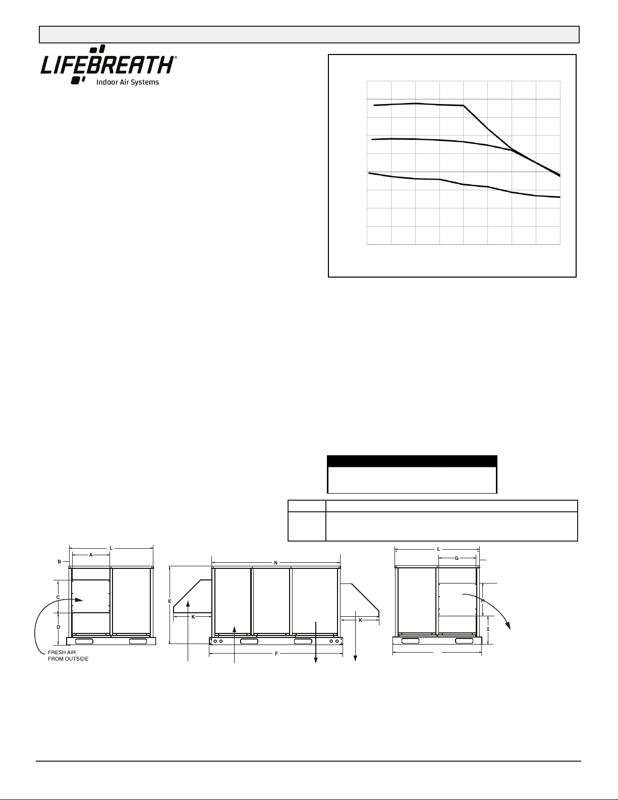
1500I-ECM
AIRFLOW PERFORMANCE
1800
1600
HIGH SPEED
1400
1200
MED SPEED
1000
800
AIRFLOW (CFM)
LOW SPEED
600
400
200
0
0.25
0.5 0.75 1.0 1.25 1.5
EXTERNAL STATIC PRESSURE (in. w.g.)
1.75 2.0
DEFROST
Factory set defrost time. Supply motor is shut off while exhaust air
defrosts core.
WEIGHT 460 lbs (210 kg) SHIPPING WEIGHT 580 lbs (260 kg)
TIMER OPTIONS
99-DET01 Lifebreath 20/40/60 Minute Timer
• Initiates high speed Ventilation for 20, 40 or 60 minutes
• 3 wire connection; 20 gauge wire (minimum)
99-DET02 Lifebreath WIRELESS 20/40/60 Minute Timer
• Initiates high speed Ventilation for 20, 40 or 60 minutes
• Wirelessly connects to main control for ease of installation
• 40' approximate range
99-RX02 Lifebreath WIRELESS Repeater
• Used to extend range of 99-DET02 Wireless Timers when
Timers are out of range
• Plugs into 120V power outlet and wirelessly connects to main
control and 99-DET02
WARRANTY
Units carry a 15 year warranty on the HRV core
and a 2 year replacement parts warranty.
DIMENSIONS 1500I-ECM (in inches)
Service Clearance 30”
INLET END VIEW
Date: ___________________________________________
Tag: _____________________Qty:___________________
Project: _________________________________________
Engineer: _______________________________________
SIDE VIEW
ECM inches 18
ECM mm
457 64 457 305 940 1695 457 457 260 64 1118
Contractor: ______________________________________
Supplier: ________________________________________
Quote#: _________________________________________
Submitted by: ____________________________________
2
ABCDEFGHIJL
2.5 18 12 37 66.75 18 18 10.25 2.5 44
NOTE: All
specifications
are subject to
change without
notice.
All units conform
to CSA and UL
standards.
OUTLET END VIEW
Page 3
Specifications
SPECIFICATIONS
AIRFLOW
1500 cfm (705 L/s) at 1.0”wg ESP.
PERFORMANCE
65% effective at 1500 cfm (705 L/s).
CORES
Six patented aluminum heat recovery cores arranged for efficient
cross-flow ventilation.
MOTORS
Two single shaft ECM variable speed, 240V, 9.1 A, 1 ph, 1 hp.
(18.2 a total) MCA: 22.8 MOP: 30
BLOWERS
Two direct drive centrifugal blowers, one per airstream.
FILTERS
Two - 20” x 16” x 2” (508 mm x 406 mm x 50 mm) pleated filters in
each airstream. MERV 6 efficiency 60% @ 4.69 microns.
CONNECTION DUCT SIZES
Two 19” x 16” (482 mm x 406 mm) to and from building under cabinet.
Two 18” x 17” (457 mm x 431 mm) hoods included on side of cabinet
with washable screens.
CABINET
20 gauge powder coated steel 1” (25 mm) thick Elastomeric insulation.
DRAIN
Two powder coated galvanized steel drain pans with 1/2” (12 mm)
O.D. drain connections.
MOUNTING
Unit to be set on support brackets hung by threaded rod type
apparatus. Brackets and rod not included.
ELECTRONICS
Integrated microprocessor circuit board. Three (3) independently
adjustable motor speeds.
CONTROL OPTIONS
99-BC02 Lifebreath Ventilation Control
• 2 speed fan setting (Low/High)
• Humidity control through adjustable Dehumidistat
• Compatible with 99-DET02 Wireless Timers
• 3 wire connection; 20 gauge wire (minimum)
99-500 3 Speed Control
• 3 Speed Fan setting (Low/Medium/High)
• 4 wire connection; 20 gauge wire (minimum)
99-DH01 Lifebreath Dehumidistat
• Humidity control through adjustable Dehumidistat
• 3 wire connection; 20 gauge wire (minimum)
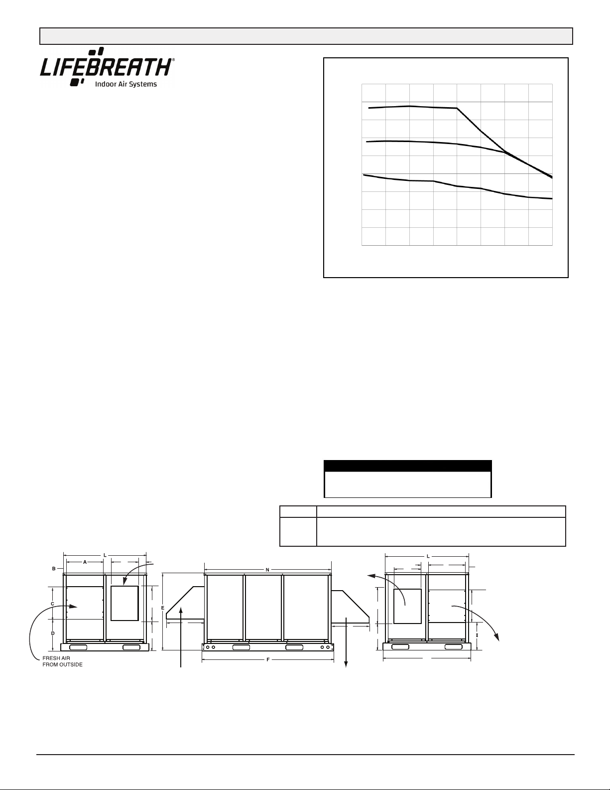
DIMENSIONS 1500E-ECM (in inches)
1500E-ECM
AIRFLOW PERFORMANCE
1800
1600
HIGH SPEED
1400
1200
MED SPEED
1000
800
AIRFLOW (CFM)
LOW SPEED
600
400
200
0
0.25
0.5 0.75 1.0 1.25 1.5
EXTERNAL STATIC PRESSURE (in. w.g.)
1.75 2.0
DEFROST
Factory set defrost time. Supply motor is shut off while exhaust air
defrosts core.
WEIGHT 530 lbs (240 kg) SHIPPING WEIGHT 650 lbs (290 kg)
TIMER OPTIONS
99-DET01 Lifebreath 20/40/60 Minute Timer
• Initiates high speed Ventilation for 20, 40 or 60 minutes
• 3 wire connection; 20 gauge wire (minimum)
99-DET02 Lifebreath WIRELESS 20/40/60 Minute Timer
• Initiates high speed Ventilation for 20, 40 or 60 minutes
• Wirelessly connects to main control for ease of installation
• 40' approximate range
99-RX02 Lifebreath WIRELESS Repeater
• Used to extend range of 99-DET02 Wireless Timers when
Timers are out of range
• Plugs into 120V power outlet and wirelessly connects to main
control and 99-DET02
WARRANTY
Units carry a 15 year warranty on the HRV core
and a 2 year replacement parts warranty.
ABC DEF G H I J K L NM
EFD inches 20 1.5 17 16.5 41 69.5 20 17 14.5 1.5 20 44 46.5 67
EFD mm 508 38 432 419 1041 1765 508 432 368 39 508 1118 1181 1702
Service Clearance 30”
INLET END VIEW
FRESH AIR
FROM OUTSIDE
STALE AIR
FROM BUILDING
SIDE VIEW
Date: ___________________________________________
Tag: _____________________Qty:___________________
Project: _________________________________________
Engineer: _______________________________________
NOTE: All
J
specifications
are subject to
change without
notice.
STALE AIR
TO OUTSIDE
M
FRESH AIR
TO BUILDING
STALE AIR
TO OUTSIDE
OUTLET END VIEW
All units conform
to CSA and UL
standards.
Contractor: ______________________________________
Supplier: ________________________________________
Quote#: _________________________________________
Submitted by: ____________________________________
3
Page 4
Specifications
SPECIFICATIONS
AIRFLOW
1500 cfm (705 L/s) at 1.0”wg ESP.
PERFORMANCE
65% effective at 1500 cfm (705 L/s).
CORES
Six patented aluminum heat recovery cores arranged for efficient
cross-flow ventilation.
MOTORS
Two single shaft ECM variable speed, 240V, 9.1 A, 1 ph, 1 hp.
(18.2 a total) MCA: 22.8 MOP: 30
BLOWERS
Two direct drive centrifugal blowers, one per airstream.
FILTERS
Two - 20” x 16” x 2” (508 mm x 406 mm x 50 mm) pleated filters in
each airstream. MERV 6 efficiency 60% @ 4.69 microns.
CONNECTION DUCT SIZES
Two 18” x 18” (457 mm x 457 mm) to building on ends of cabinet.
Two 18” x 17” (457 mm x 431 mm) hoods included on side of cabinet
with washable screens.
CABINET
20 gauge powder coated steel 1” (25 mm) thick Elastomeric insulation.
DRAIN
Two powder coated galvanized steel drain pans with 1/2” (12 mm)
O.D. drain connections.
MOUNTING
Unit to be set on support brackets hung by threaded rod type
apparatus. Brackets and rod not included.
ELECTRONICS
Integrated microprocessor circuit board. Three (3) independently
adjustable motor speeds.
CONTROL OPTIONS
99-BC02 Lifebreath Ventilation Control
• 2 speed fan setting (Low/High)
• Humidity control through adjustable Dehumidistat
• Compatible with 99-DET02 Wireless Timers
• 3 wire connection; 20 gauge wire (minimum)
99-500 3 Speed Control
• 3 Speed Fan setting (Low/Medium/High)
• 4 wire connection; 20 gauge wire (minimum)
99-DH01 Lifebreath Dehumidistat
• Humidity control through adjustable Dehumidistat
• 3 wire connection; 20 gauge wire (minimum)
DIMENSIONS 1500E-ECM-E (in inches)
ECM inches 20 1.5 17 16.5 41 69.5 18 2.5 14.5 16 44 46.5 67
ECM mm 508 38 432 419 1041 1765 457 64 368 406 1118 1181 1702
1500E-ECM-E
AIRFLOW PERFORMANCE
1800
1600
HIGH SPEED
1400
1200
MED SPEED
1000
800
AIRFLOW (CFM)
LOW SPEED
600
400
200
0
0.25
0.5 0.75 1.0 1.25 1.5
EXTERNAL STATIC PRESSURE (in. w.g.)
1.75 2.0
DEFROST
Factory set defrost time. Supply motor is shut off while exhaust air
defrosts core.
WEIGHT 530 lbs (240 kg) SHIPPING WEIGHT 650 lbs (290 kg)
TIMER OPTIONS
99-DET01 Lifebreath 20/40/60 Minute Timer
• Initiates high speed Ventilation for 20, 40 or 60 minutes
• 3 wire connection; 20 gauge wire (minimum)
99-DET02 Lifebreath WIRELESS 20/40/60 Minute Timer
• Initiates high speed Ventilation for 20, 40 or 60 minutes
• Wirelessly connects to main control for ease of installation
• 40' approximate range
99-RX02 Lifebreath WIRELESS Repeater
• Used to extend range of 99-DET02 Wireless Timers when
Timers are out of range
• Plugs into 120V power outlet and wirelessly connects to main
control and 99-DET02
WARRANTY
Units carry a 15 year warranty on the HRV core
and a 2 year replacement parts warranty.
ABC DEF G H I K L NM
G
INLET END VIEW
STALE AIR FROM
H
BUILDING
G
K
FROM OUTSIDE
A
FRESH AIR
Service Clearance 30”
SIDE VIEW
Date: ___________________________________________
Tag: _____________________Qty:___________________
Project: _________________________________________
Engineer: _______________________________________
FRESH AIR TO
BUILDING
H
G
B
NOTE:
specifications
A
are subject to
change without
notice.
STALE AIR
TO OUTSIDE
A
STALE AIR
TO OUTSIDE
G
K
OUTLET END VIEW
C
M
Contractor: ______________________________________
Supplier: ________________________________________
Quote#: _________________________________________
Submitted by: ____________________________________
4
All
All units
conform to
CSA and UL
standards.
Page 5
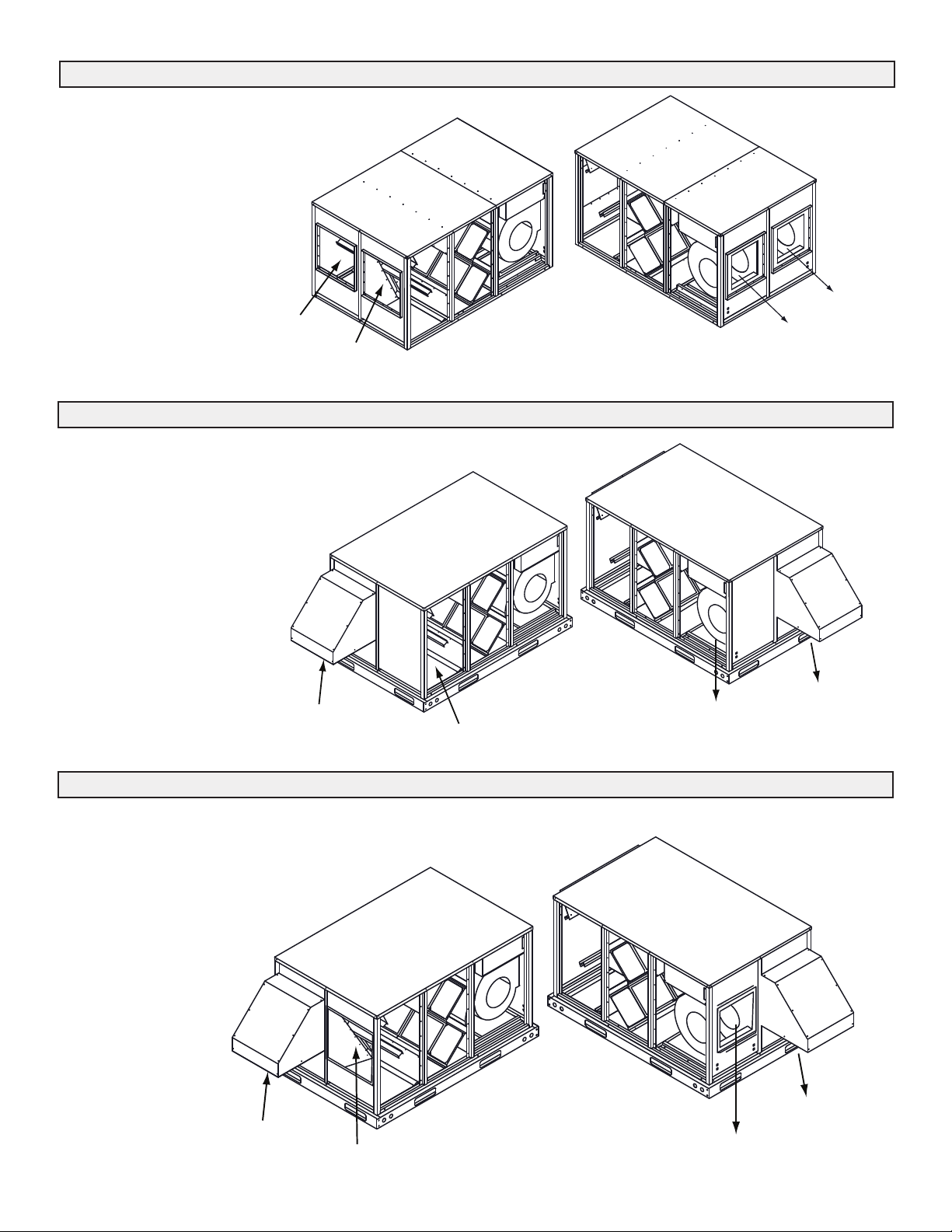
Duct Configuration Model 1500I-ECM
The 1500I-ECM is designed for indoor
installa-tions. The duct connections for the
Stale Air From Building and Fresh Air to
Building ducts are at the ends of the unit.
STALE AIR
TO OUTSIDE
FRESH AIR
FROM OUTSIDE
STALE AIR
FROM BUILDING
FRESH AIR
TO BUILDING
Duct Configuration Model 1500E-ECM
The 1500E-ECM is designed for
outdoor rooftop installations. The duct
connections for the Stale Air From
Building and Fresh Air to Building
ducts are located at the bottom of the
unit. A roof curb is required for this
installation.
STALE AIR TO OUTSIDE
FRESH AIR
FROM OUTSIDE
STALE AIR FROM
BUILDING
FRESH AIR TO BUILDING
Duct Configuration Model 1500E-ECM-E
The 1500E-ECM-E is designed for outdoor
installations. The duct connections for the Stale Air
From Building and Fresh Air to Building ducts are at
the ends of the unit.
STALE AIR TO OUTSIDE
FRESH AIR
FROM OUTSIDE
STALE AIR FROM
BUILDING
5
FRESH AIR TO BUILDING
Page 6
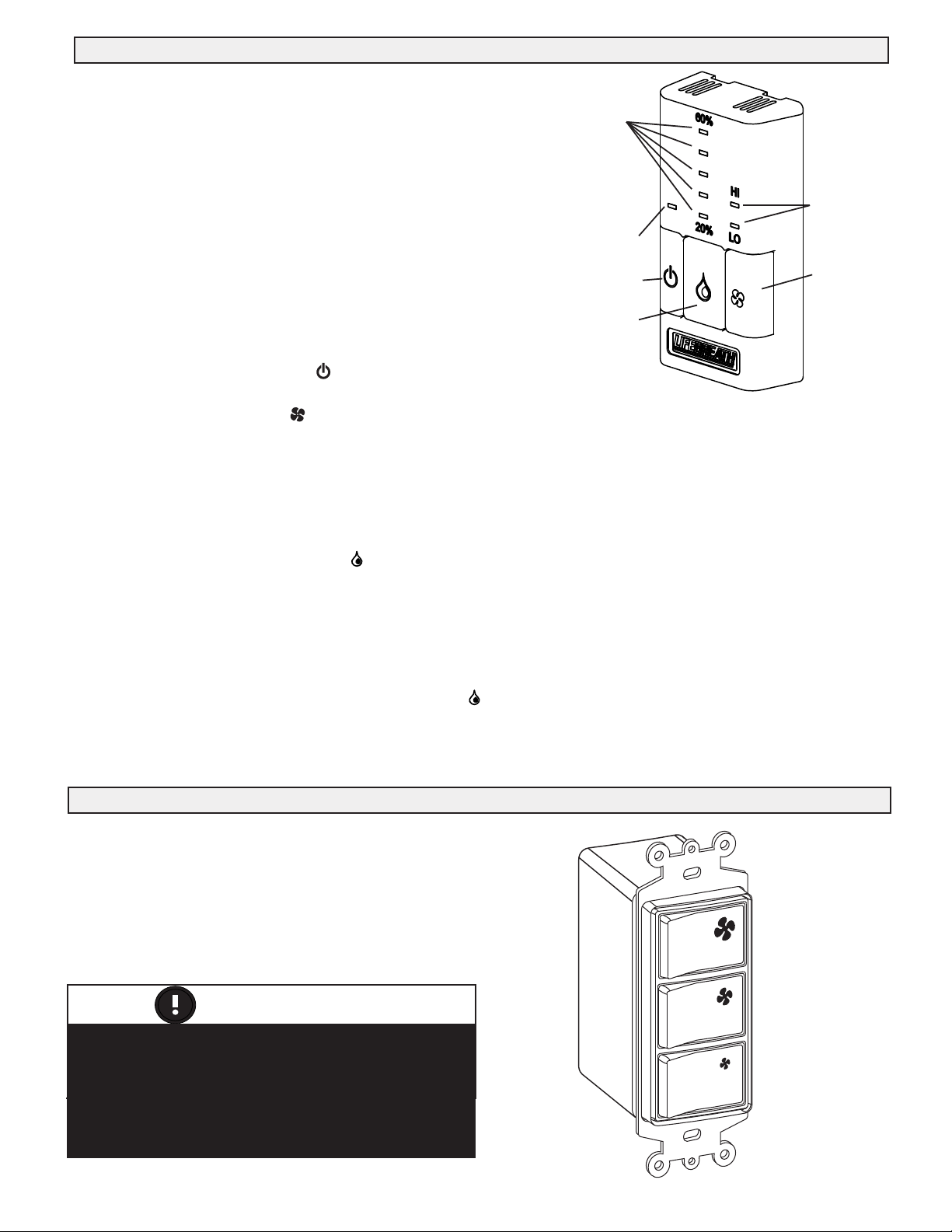
Optional Lifebreath Ventilation Control - Part #99-BC02
Key Features:
2 speed fan setting (LOW / HIGH)
Standby setting (fan OFF)
Electronic Dehumidistat
Compatible with 99-DET02 Wireless
Timers
Slim-line design
Connect to 3 wire 20 gauge low voltage
wire
BC02 Operating Instructions:
Humidity
Setting
ON/OFF Light
ON/OFF Button
Dehumidistat
Button
Fan Speed
Indicator
Fan Speed
Button
Turning on the Control
Press and release the ON/OFF button . The light above will illuminate.
Setting the Ventilation Speed
Press and release the Fan button to select LOW or HIGH fan speed. The corresponding “Indicator Light" will illuminate. If
both LO and HI indicator lights are off, the fan is OFF but will turn ON if required by the Dehumidistat or remote Timer (if
installed).
Humidity Control
Your unit will reduce indoor humidity when outdoor humidity levels are lower than indoor humidity levels. This feature is only
effective when the outdoor temperature is below 59˚F (15˚C).
Setting the Dehumidistat
Press and release the Dehumidistat button until the Dehumidistat Light is at the desired setting. After a few seconds the
Dehumidistat light will either flash or be on continuous.
A flashing light indicates the humidity level is higher than the setting and the unit is operating on high speed ventilation. A
continuous light indicates the humidity level is lower than the setting. Refer to the unit's Home Owner’s manual for instructions
on how the Dehumidistat works.
The Dehumidistat will override the current speed setting to HIGH speed.
button until no Dehumidistat light is on.The Dehumidistat function can be turned OFF by pressing the
Note - Only 1 Dehumidistat should be installed in a system.
Optional Lifebreath 3 Speed Control - Part #99-500
Key Features:
• 3 Speed Fan setting (LOW / MEDIUM / HIGH)
• 4 wire; 20 gauge wire (minimum)
• Connect to Red, White, Yellow, Green.
OFF
HIGH
ATTENTION
When used in conjunction with the 99-BC02, the
BC02 control must be ON for the 99-500 control
to operate. The 99-BC02 will override the
99-500 control when the Dehumidistat is
operating or the control is set to HIGH speed.
OFF
MED
OFF
LOW
6
Page 7
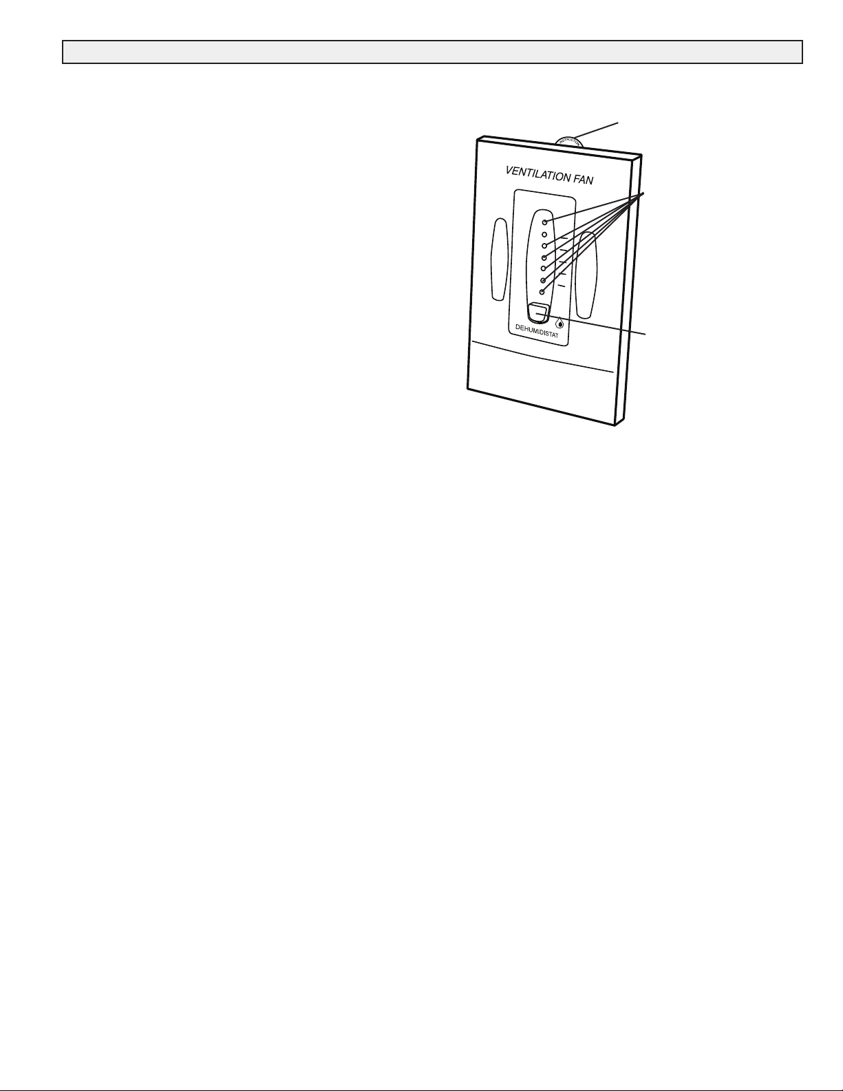
Optional Lifebreath Dehumidistat - Part #99-DH01
Key Features
• The Dehumidistat measures the indoor humidity level and
will initiate high speed ventilation when the moisture level
in the building exceeds the set point on the control.
• Once the humidity in the building is reduced, the
HRV will
revert back to its previous setting.
• The Dehumidistat should be set to OFF for all season
except the heating season.
• Connect to 3 wire 20 gauge low voltage wire.
Humidity Control
Your HRV will produce a dehumidifying effect when outdoor
humidity levels are lower than indoor humidity levels. Never
use the Dehumidistat feature when outdoor temperatures are
above 59 F (15 C).
Note: The indoor humidity level is measured at the control.
Setting the Dehumidistat
Press and release the Dehumidistat button until the
Dehumidistat Light is at the desired setting. After 5 seconds the
Dehumidistat light will either flash or be on continuous.
A flashing light indicates the humidity level is higher than the
setting and the unit is operating on high speed ventilation. A
continuous light indicates the humidity level is lower than the
setting. Refer to the unit's Operation & Installation Manual for
instructions on
Note - Only 1 Dehumidistat should be active on a system.
how the Dehumidistat works.
Instruction card
Dehumidistat
%
80
Indicator LEDs
Set to the desired
humidity level. High
speed ventilation will
initiate when the indoor
moisture level exceeds
the set point on the
20
control.
Dehumidistat
Adjust button
7
Page 8
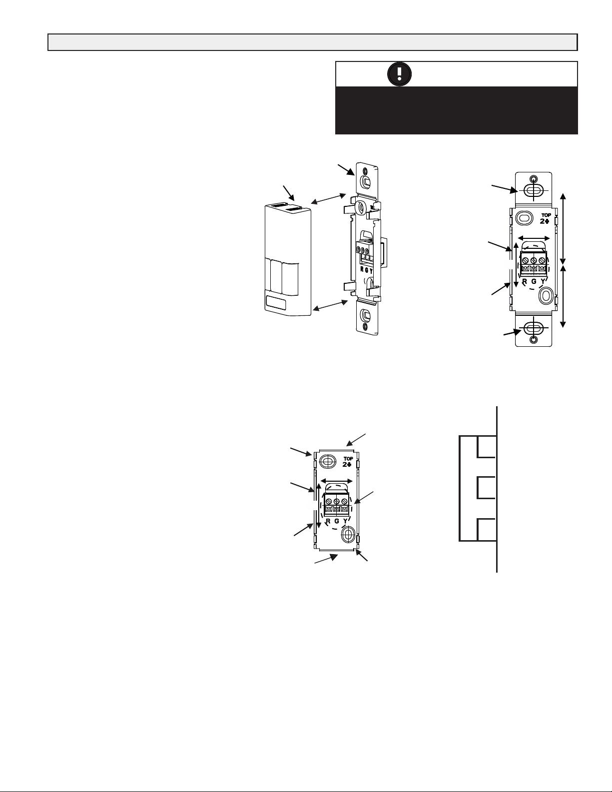
Connecting Optional Control - Part #99-BC02
The control may be installed onto a flush mounted 2" x 4" electrical
switch box or it may be surface mounted onto a wall.
Only 1 master control should be installed to a ventilation system
(the Face Plate on this illustration may not be exactly the
same as yours).
1. Separate the Face Plate from the Back
Plate by firmly pulling apart (Figure
Be careful not to damage Face
Plate Contact Pins.
2. For
mounting the control without a
Decora plate, break off top and
bottom tabs and refer to Figure C for
mounting.
A).
Figure A
Face Plate
3. Place the Back Plate of the control in the
desired location on the wall and pencil
mark the top and bottom screw holes
(Figure B or C).
4. Remove the Back Plate and mark the
center hole for the wires in the middle of
the screw holes. Refer to Figure B or
C for placement.
5. Cut in a 3/4 in by 1
wall to allow for the wire opening and
drill (two) 1/8 in holes for the screws and
wall anchors (Figure
in oval hole in the
B or C).
6. Pull 3 wire 20 gauge (min.) 100 ft length
(max.), through the opening in the wall.
7. Connect red, green, and yellow to the
Wiring Terminals located on the Back
Plate (Figure B or C).
8. Attach the Back Plate to the wall using
the 2 supplied screws and anchors.
9. Attach the Face Plate to the Back Plate
(Figure A). Note: Be careful to
correctly align the Face Plate to avoid
damaging the Face Plate Contact Pins.
Keep top / bottom
vent openings clear
Figure C
Alternate Wall Mount
1/8 in hole for
screw and
anchor
1 in x 3/4 in
oval hole
for wire
opening
Wiring
Terminals
10. Connect the 3 wire 20 gauge (min.) 100
ft length (max.) to the digital controls
terminal strip located on the Aircom
circuit board (Figure D).
Break off tab
ATTENTION
Pay special attention not to damage the Contact
Pins when attaching and detaching the Face Plate.
(Figure B)
Back Plate
0.75"
1"
Break off tab
Wire hole
centered
between
screw
holes
1/8 in
hole for
screw and
anchor
Figure B
1/8 in hole for
screw and
anchor
1 in x 3/4 in
oval hole
for wire
opening
Wiring
Terminals
1/8 in hole
for screw and
anchor
REDGRNYEL
DET
Digital Controls
Figure D
Terminal strip on
Aircom circuit
board
• Yellow to YEL
• Red to RED
• Green to GRN
• Use 3/20
1.625"
0.75"
1"
1.625"
wire
8
Page 9
P
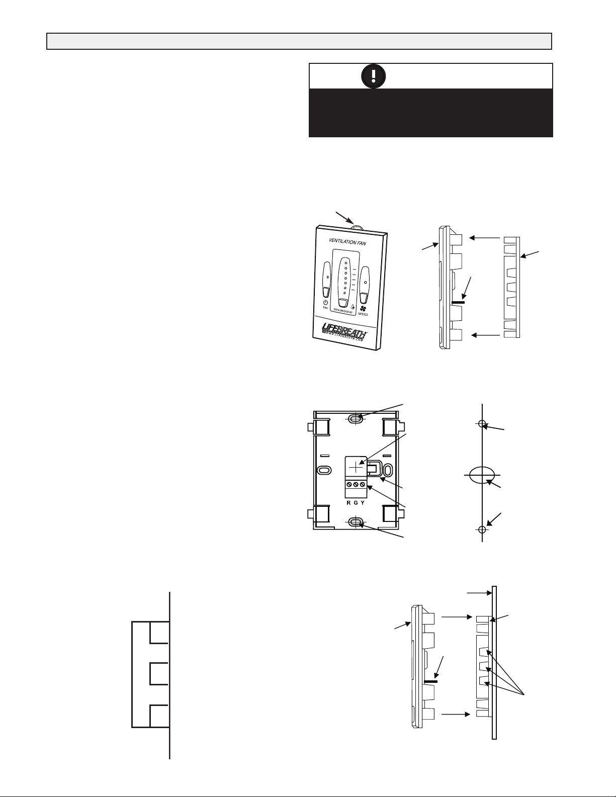
Connecting Optional Control - Part #99-DH01
The Lifebreath Dehumidistat may be installed onto a
flush mounted 2" x 4" electrical switch box or it may be
surface mounted onto a wall.
Only 1 master control should be installed to a ventilation
system (the Face Plate on this illustration may not be
exactly the same as yours).
1. Remove the Operating Instructions Card from the
top of the Control (Figure A).
2. Separate the Face Plate from the Back Plate by
firmly pulling apart (Figure B). Be careful not to
damage Face Plate Contact Pins.
3. Place the Back Plate of the control in the desired
location on the wall and pencil mark the wall in
the center of the Wire Opening, Top Screw Hole
and Bottom Screw Hole (Figure C).
4. Remove the Back Plate and drill a 3/8" opening in
the wall to allow for the Wire Opening and a 1/8"
hole for the Wall Anchors for the top and bottom
screw holes (Figure D).
5. Pull 3/20 wire through the opening in the wall
and the Wire Opening of the Back Plate (Figure C).
6. Connect Red, Green and Yellow to the Wiring
Terminals located on the Back Plate (Figure C).
7. Secure a single wire to the Wire Retainer located
on the Back Plate (Figure C).
8. Attach the Back Plate to the wall using the 2
supplied screws and anchors.
9. Attach the Face Plate to the Back Plate (Figure
B). Note: Be careful to correctly align the Face
Plate to avoid damaging the Face Plate Contact
Pins.
10. Insert the Operating Instructions Card into the
control (Figure A).
11. Connect the 3 wire 20 gauge (min.) 100 ft length
(max.) to the digital controls terminal strip located
on the Aircom circuit board (Figure E).
ATTENTION
Pay special attention not to damage the Contact
Pins when attaching and detaching the Face Plate.
(Figure B)
Figure A - Face Plate
Operating
Instructions Card
%
80
HIGH
20
Figure C
Front View of Back Plate
TOP
Top Screw
Hole
Wire
Opening
Wire
Retainer
Wiring
Terminals
Bottom
Screw Hole
Face
Plate
Figure B
Side View
Face Plate
Contact
Pins
Figure D
Drill holes in
wall
Separate the
Face Plate from
the Back Plate.
Drill a 1/8” hole
for the Top Screw
and Anchor
Drill a 3/8” hole
for the Wire
opening
Drill a 1/8” hole
for the Bottom
Screw and
Anchor
Back
Plate
Digital Controls
DET
Figure E
Terminal strip on
Aircom circuit
board
REDGRNYEL
• Yellow to YEL
• Red to RED
• Green to GRN
• Use 3/20 wire
Figure F
Correct Installation
of Back Plate
9
Face
Plate
Wall Face
Face Plate
Contact
Pins
Back
Plate
Dehumidistat Sensor
Openings to room
air allow accurate
sensor readings.
Page 10

Optional Lifebreath Wireless Timer - Part #99-DET02
The timer will override the operational mode
(regardless of the settings) and initiate HIGH speed
Ventilation. Upon
completion of the timer cycle, the HRV
will return to your selected operational mode and speed
setting.
Initiates HIGH speed ventilation for 20, 40 or 60 minutes. The
20/40/60 minute Status Lights indicate HIGH speed
operation.
The Wireless Timers are to be surface mounted onto a
wall. Multiple Wireless Timers may be installed in
a ventilation
system. To increase the range of a Wireless Timer, a RX02
Repeater should be used.
Pairing:
1. Turn on the main wall control by pressing the ON/OFF
button and remove the battery from Timer.
2. Press the left and right buttons simultaneously on the
main wall control ( and ). The bottom row of 3
LED's will begin flashing. This indicates that the
main control is now in pairing mode. (Figure D)
3. Keep the Timer within 16” of the main wall control
when pairing.
4. Install the battery in the DET02 Timer. All four lights
on the Timer will immediately flash 5 times, then only
the red battery light will remain on for approximately
12 seconds after which the "40" light flashes the rev
code. 20, 40, 60 lights will flash until paired or will
stop if not paired within 12 seconds. If pairing was not
successful you now must return to step 1 to restart the
pairing process.
5. Press the button on the main wall control to exit
Alternate Wall Mount
1/8 in hole for
screw and anchor
pairing mode when Timers have been successfully
paired.
To pair additional DET02 Timers with the same wall
control, or if pairing was not successful, repeat steps
1-6.
When
paired, the DET02 Timers can be moved and
installed elsewhere. Estimated range of the Timer is 40’
with no obstructions. A RX02 Repeater may be installed to
increase the range of the Timers.
Test if pairing was successful by pressing the Select Button
and listen for the HRV to initiate HIGH fan speed
Ventilation.
Un-pairing:
1. Remove the battery from the back of the DET02 Timer
2. Press and hold the Select Button on the front of the
Timer
3. While holding the Select Button, reinsert the battery in
the Timer. Continue holding the Select Button until the
LED under "40" begins flashing. The DET02 Timer will
now be unpaired with the main wall control.
The Wireless Timers and Repeaters must be
matched to the main wall control of the HRV.
This process is called "Pairing". Multiple
Timers and Repeaters can be paired to a single
wall control.
Figure A
Face Plate
Figure
E
DET02 Timer
Removable
Backplate
20/40/60 Minute
Status Lights
Select Button
initiates high speed
ventilation for 20, 40
or 60 min.
Back Plate
Break off tab
Break off tab
ATTENTION
Figure B
1/8 in hole for
screw and
anchor
1/8 in hole
for screw and
anchor
Figure C
1/8 in
hole for
screw and
anchor
Figure D
BC02
Control
Press Simultaneously to
Initiate Pairing Mode
10
Battery Indicator
Page 11

Optional Wireless Timer - Part #99-DET02
Continued
Installation of Wireless Timer
1. Separate the Face Plate from the Back Plate by firmly pulling apart (Figure A).
2. For mounting the control without a Decora plate, break off top and bottom tabs and refer to Figure C for mounting.
3. Place the Back Plate of the control in the desired location on the wall and pencil mark the top and bottom screw holes (Figure B
or C). Drill two 1/8" holes.
4. Attach the Back Plate to the wall using the 2 supplied screws and anchors.
5. Attach the Face Plate to the Back Plate (Figure A).
Removable
Overview of Lifebreath Wireless 20/40/60 Minute Timer
Initiates HIGH speed Ventilation for 20, 40 or 60 minutes. The
20/40/60 minute Status Lights indicate HIGH speed operation.
Wireless Timers have an estimated range of 40' with no obstructions. To
increase the range of a Wireless Timer a 99-RX02 Repeater may be used.
Using the Wireless Timer
When paired to the main wall control, the Wireless Timer may be moved to
a remote location in the home such as a bathroom.
Pressing the Select Button on the Timer will initiate HIGH speed
fan operation. The corresponding Status Light will illuminate under the
number on the Timer to indicate either 20, 40 or 60 minutes of HIGH
speed fan operation. To cancel the call for HIGH speed fan operation, press
the Select Button until the Status Lights are no longer illuminated.
20/40/60
Minute Status
Lights
Select Button
initiates high speed
ventilation for 20, 40
or 60 min.
Battery Indicator
Backplate
Replacing the Battery
When the battery needs to be replaced in the Wireless Timer, the red LED
Battery Indicator will illuminate.
To replace the battery, first remove the Face Plate by pulling it off the wall.
On the back of the Timer Face Plate the battery will be exposed. Replace
the battery and re-attach the Face Pate to the Back Plate. Be careful not to
damage the tabs on the Back Plate when re-attaching the Face Plate.
Back of
99-DET02
Face Plate
Battery
Back Plate
Face Plate
11
Page 12

Optional Lifebreath Wireless Repeater - Part #99-RX02
Installation and Pairing of Wireless Repeaters: 99-RX02
The RX02 Repeaters are to be plugged directly into a 120V power outlet.
1. Turn on the main wall control by pressing the ON/OFF button .
2. Press the left and right buttons simultaneously on the main wall control ( and ). main control). The bottom row of 3
LED's will begin flashing. This indicates that the main control is now in pairing mode.
3. The RX02 Repeater must be powered within 16” of the main wall control for pairing. If an outlet is not available an extension
cord should be used to power the repeater initially for pairing.
4. Plug the RX02 Repeater into the power outlet. The green light will flash after approximately 12 seconds indicating that the
repeater is paired with the main wall control.
5. Press the ON/OFF button on the main wall control to exit pairing mode and the Repeater may now be
unplugged and moved to its permanent location.
To pair additional RX02 Repeaters with the same wall control, repeat steps 1-5 until all Repeaters
have been paired.
When installed in its permanent location, the green LED will remain solid to indicate the best
location and the Repeater can be moved farther if required. The green LED will flash to indicate it
is in a good location. A red light indicates the Repeater is out of range and needs to be moved
closer to the main wall control.
NOTE: Wireless Repeaters cannot be used in a network to extend the range of another Wireless
Repeater.
RX02
Repeater
Power
Plug
Optional Lifebreath 20/40/60 Minute Timer - Part #99-DET01
Operating your Lifebreath 20/40/60 Minute Fan
Timer
Press and release the Select Button to activate a 20, 40 or 60
minute high speed override cycle. The High Speed Status
Light will illuminate and the unit will run on high speed
ventilation for the selected time.
The High Speed Status Light will dim after 10 seconds of run
time.
The High Speed Status Light will flash during the last 5
minutes of the cycle.
The timer connected to the unit will illuminate for the
duration of the override when the Select Button is pressed.
Lockout Mode
Lockout Mode is useful if you wish to disable the timers.
The timer can be set to lockout mode by pressing and holding
the Select Button for five seconds. After five seconds, the
High Speed Status Light will flash; release the Select Button.
The timer is now in lockout mode. If the Select Button is
pressed during lockout mode the High Speed Status Light will
momentarily illuminate but no override will be initiated.
If lockout mode is initiated when the timer is activated, the
timer will continue its timed sequence but will not allow any
further overrides to be initiated. Lockout mode can be
unlocked by pressing and holding the Select Button for five
seconds. After five seconds the High Speed Status Light will
stop flashing. Release the Select Button and the timer will
now operate normally.
High Speed
Status Lights
Select Button
initiates high
speed ventilation
for 20, 40 or 60
minutes.
• Timers mount in standard 2” x 4” electrical boxes.
• Wire multiple timers individually back to the unit.
• Use 3/20 low voltage wire
Yellow
Red
Green
NOTE ABOUT TIMERS
Terminal strip on
Aircom circuit
board
REDGRNYEL
• Yellow to YEL
• Red to RED
DET
• Green to GRN
• Use 3/20 wire
12
Digital Controls
Page 13

Function and Controls
Basic Functions
Speed control is obtained by powering 24V to one of
the designated speed taps.
Example:
A jumper between the R terminal and the
G terminal will result in low speed operation.
HIGH
24V
Thermostat
HIGH
MED
OGYWRC
LOW
Micro Processor Board
12Vac Com C
T25 T26 T27 C R W Y G O YEL GRN RED T28 T29
P1
Thermostat DET
MED
LOW
Jumper Wire
Placement
on Micro
Processor
Jumper
Wire
Board
Optional 3 Speed Control (Part #99-500)
Connect to R, W, Y and G on Thermostat
OFF
OFF
OFF
Setup
Select appropriate operational speed by
jumper wire between
of the designated speed
one
taps.(A jumper wire is factory installed in the low
speed position.)
Note:
is recommended to use the optional speed control
It
Part # 99-500 in order to obtain 3 speed fan control.
JUMPER
ADJUSTED BY QUALIFIED
TECHNICIANS ONLY.
DIP SWITCHES TO BE
QUALIFIÉ PEUT AJUSTÉ LES
SEUL UN TECHNICIEN
COMMUTATEURS DIP.
SW1
SPEED
High R W
Medium R Y
Low R G
Line/Ligne
CHASSIS
T44
T1
T2
T3
T4
T5
T6
T21 T22
AUX 1
T23
AUX 2
T24
8 7 6 5 4 3 2 1
installing
the
Front View
Optional 20/40/60 Minute Timer
Part# 99-DET01
Boost unit to Ventilation Mode for 20, 40,
60 minutes (no speed change).
Connect up to 4 maximum
Connect to Yellow, Red & Green
Back View
Digital Controls
P2 P3
Freeze
Defrost
2 AMPS
R
24Vac
T30
N.0. COM N.C. N.0. COM N.C. N.0. COM N.C. N.0.COM
Contact 1
T31
T32
T33
Contact 2 Contact 3 Contact 4
T34
T35
T36
T37
T38
T39
T40
T41
T42
ON
K6
K8 K7 K1 K2
K3 K4 K5
T11 T12
Neutral/Neutre
COM
N.O.
COM
N.O.
COM COM
N.O. N.O.
Fan Hi Fan Med Fan Low
T13
T14
T15
T16
OR
C4
C3
T17
Refer to “Connecting
Optional Control”
C2 C1
T18
manual for instructions on
connecting the optional
%
80
20
in this
Lifebreath Ventilation Control
(Part# 99-BC02) and optional
T19
Lifebreath Dehumidistat
(Part# 99-DH-01)
SPARE
N.C
T43
RELAY
FEED
T20
Connect to Yellow, Red & Green
13
Page 14

Aircom Relays
The Aircom circuit board has three available “dry
contact” relays. Contact 3 is not
available.
Maximum 115V 10 amp resistive load.
Contact 2 and 4
These relays
initiate whenever the HRV fans are
operating.
F2 MAX 2
P2 P3
Defrost
Freeze
amp
T39
T40
SPARE
T43
N.C
T42
T41
K7 K1 K2K8
N.0. COM N.C. N.0. COM N.C. N.0. COM N.C. N.0 . COM
R
24Vac
T30T29T28
T31
Contact 1
T32
T33
T34
T35
T36
T37
Contact 2 Contact 3 Contact 4
T38
14
Page 15

Servicing
The 1500I-ECM and 1500E-ECM are designed to be
serviceable from either side. If access to the unit will only
be available from one side, the unit must be set up
accordingly. The unit is factory shipped to be serviced from
the front. (Blowers on the right when facing the unit. If
servicing is only accessible from the other side follow the
procedure below.
1. The Ebox must be removed from the front brackets
and mounted on the rear brackets provided on the
other side of the unit
2. The filter divider panels must be removed and placed
in the unit so they can be removed from the
opposite side.
3. The lower blower divider panel must be removed
and mounted in the unit from the other side.
Each panel on the unit can be removed by removing
the two bolts on the bottom.
Servicing is easiest by removing the side panels on
both sides to gain access to either side of the unit.
Servicing Filters
1. Remove filter service panel (one or both sides)
2. Remove first set of filters.
3. Remove filter divider panels (if only accessing from
one side)
4. Remove filters from behind filter divider panel
5. Replace all filters. Ensure that filter divider panels are
re-inserted into unit.
Servicing Cores
1. Remove core service panel (one or both sides)
2. Slide cores out (regular core maintenance).
3. When placing the cores back into the unit, ensure
that there are no gaps between any of the cores.
Ensure all H channels are flush with the ends of the
cores before the core service panel is re-attached.
Servicing Blowers
1. Remove blower service panel (one or both sides)
2. Unscrew the 2 bolts that connect the blower to the
blower rails of the unit.
3. Remove all wiring to the motors.
4. Slide blower back and lift to remove blower assembly.
5. If access to the unit is not available from both
sides, remove the blower divider panel by removing
the 8 bolts holding this panel in place.
6. For EFD model, unscrew the 4 bolts that connect
the downward facing blower to the blower rails. Lift
out blower assembly. (End panel can be removed to
facilitate blower removal).
7. Repeat steps 2-4 with the other blower.
15
Page 16

Mounting the 1500
Option 1
Unit can be suspended with “U” channels and Threaded Rod
Option 2
Unit can be placed on blocks (sleepers)
16
Page 17

Roof Curb Assembly Instructions
Frame Assembly
1. Take one end piece (locking tabs) and one side
piece (slots). Stand both pieces vertically on the
floor or roof. See Figure 1.
2. Raise slightly the corner of the end piece
(locking tabs) and mate with side piece (slots),
ensuring that lower locking tab with leading edge
is through slot opening. See Figure 2.
3. Push down on top edge of end piece. Ensure
that all 3 of the locking tabs are feeding into
each corresponding slot. Once both pieces are
flush, the process is complete. See Figure 3.
4. Drive one spike provided into wood nailer strips
at each corner. See Figure 3.
Frame Application and Location
This roof mounting frame provides necessary
support when the unit is installed. The frame can be
installed directly on deck having adequate structural
strength or on roof supports under deck.
Securing the Frame
To ensure proper mating with unit, it is critical
that mounting frame be squared to the roof, as
follows:
1. With frame situated level in desired location on
roof trusses, tack weld one corner of frame.
2. Measure frame diagonally from one corner to
the opposite corner. Repeat with the remaining
two corners. These dimensions must be equal for
the frame to be square.
3. It is extremely important to sight frame from all
corners to ensure that the frame is not twisted
across top side. Shim frame under any low sides.
4. After frame has been squared, straightened and
shimmed, weld or attach frame securely to roof.
Roof Curb Assembly
Figure 1
side piece
slot for tab
Figure 2
wood nailer strip
side piece
slot for tab
Figure 3
end piece
locking tab
wood nailer strip
end piece
locking tab
MAX. SLOPE TOLERANCE: 1/16" per linear foot in
any direction.
Note specification of duct location on bottom of
HRV when positioning cross members (duct cavity).
See next page.
wood nailer strips
spike
tabs through slots
17
Page 18

Roof Curb
Detail
STALE AIR
RETURN
DUCT COLLAR
SUPPORTS
FRESH AIR
SUPPLY
FACTORY INSTALLED
PERIMETER WOODEN
NAILER STRIP
TOP VIEW
42 3/4”
(1086 mm)
(356 mm)
(483 mm)
1-3/4” (
45 mm)
1-3/4” (
45 mm)
14”
19”
STALE AIR
RETURN
16”
(406 mm)
65-3/4”
(1670 mm)
SIDE VIEW
FRESH AIR
SUPPLY
16”
(406 mm)
19”
(483 mm)
1-3/4” (
45 mm)
1-3/4” (
45 mm)
18
Page 19

Ducting - General
Drains
Connect the drain pans in the bottom of the HRV to a
drain line fastened to the holes provided. Create a "P"
trap to prevent odors from being drawn through. Make
sure the drain line slopes down to drain properly and if
this is not possible a condensate pump will be required
for removal of the water. Note that stagnant water is a
leading cause of indoor air quality problems; confirm
drainage after installation by pouring water into trays.
Drain line must be installed where it will not freeze.
The Ductwork System
A well designed ducting system will allow the HRV to
operate at its maximum efficiency. Avoid the use of
under-sized ducting and sharp radius bends and tees
which can significantly increase the system pressure
drop and reduce the air flows.
NOTE: Fully insulated ducting with an integral vapor
barrier must be used on all runs passing through
unheated areas in order to avoid condensation problems
and energy losses from the air streams.
* Consult local Codes
To minimize pressure drop and noise, galvanized metal
ducts sized for 725 fpm (3.68 m/s) (maximum velocity)
are recommended. Keep ducting as short as possible and
use a minimum of elbows and tees. Connecting sections
and shorter runs may be flexible ducting one size larger
than the metal duct. Use flexible duct connectors at the
HRV to avoid noise transmission.
All duct joints must be secured with screws, rivets or
duct sealant and sealed with aluminum duct tape to
prevent leakage.
Outside Weatherhoods
The 1500E-ECM is shipped with 2 weatherhoods inside
the cabinet which attach to the outer ends of the
cabinet using bolts provided. The 1500I-ECM requires
hoods to be built elsewhere and provided by the
contractor.
NOTE: It is extremely important to design and install
the fresh air intake in an area where the hoods will
gather the freshest air, free from restriction.
Recommended:
• no less than 10 ft. (3 m) apart from each other
• at least 18 in. (46 cm) above ground level
• away from sources o
f contaminants, such as
automobile exhaust fumes, gas meters, garbage
containers, cooling towers, etc.
• not exposed to prevailing winds, whenever
reasonably possible.
The outside perimeter of the weatherhood must be
caulked to prevent leakage into the building.
The design and size of the weatherhoods or louvers
chosen by the installer must allow for adequate free
area. Water and snow penetration of the system is
minimized when the airflow does not exceed 750 FPM
(3.81m/s) free area velocity.
Ducting from the Weatherhoods
Galvanized sheet metal ducting with sufficient cross
section with an integral single piece vapor barrier
should be used to connect the HRV to the
weatherhoods. All ducting must meet ULC Class 1 Fire
Rating.
A minimum R value of insulation should be equal to 4
(RSI 0.75), or as stated in local codes.
A good bead of high quality caulking (preferably
acoustical sealant) and taping with a high quality
aluminum foil tape is recommended to seal the duct to
both the HRV and the weatherhood.
Warm-side Ducting - General
Ducting from the HRV to different areas within the
building should be galvanized metal whenever possible.
To minimize airflow losses in the ductwork system, all
ducts should be as short as possible and with as few
bends or elbows as possible. 45Þ elbows are preferred
to 90Þ elbows, whenever possible. Use Y tees instead
of 90Þ tees whenever possible.
All duct joints must be fastened securely and wrapped
with a quality duct tape to prevent leakage. We
recommend aluminum foil tape.
19
Page 20

Ducting - Distribution
Stale Air Return System
The stale air return system is used to draw air from
the points in the building where the worst air quality
problems occur. Return air suction points should be
located at the opposite side of the room to the fresh air
inlet. The inlets may be located in the ceiling or high on
the walls and fitted with inlet grilles.
Many commercial activities produce air contaminants in
the form of dusts, fumes, mists, vapors and gases.
Contaminants should be controlled at the source so
that they are not dispersed through the building nor
allowed to increase to toxic concentration levels. The
heat recovery ventilator allows for economical operation
of the HVAC system while effectively removing
contaminants from the space. In designing the exhaust
portion of the system the exhaust grilles are placed
so as to remo
ve the contaminants while not
allowing them to enter the breathing zone of the
occupants.
For contaminants that are lighter than air, grilles should
be located high on the wall. If contaminants are heavier
than air, a lower placement of the grilles will be
required. Information on a contaminants specific
gravity
and toxicity should be available from the chemical data sheets.
Fresh Air Supply System
The fresh air supply ductwork from the HRV may be
directly connected to the return air duct of the forced
air system. When directly connected it is recommended
that the air handler blower be in constant operation to
move the fresh air about the building Also, it is
advisable to include a short length of fabric flex
duct o
r other non-metallic connector in this hard
ducted line in order to keep the HRV acoustically
isolated and separately grounded (electrically) from
the air handler. This will avoid a possible shock hazard
to service people if a short to ground develops in
one of the devices. It may be necessary to install a
separate fresh air supply ductwork system if the heating
is other than forced air.
When installing an HRV, the designer and installer
should be aware of local codes that may require smoke
detectors and/or fire stats in the HVAC or HRV
ductwork. Because an HRV is designed to bring fresh
air into the building, structures may require a supply
voltage interrupt when smoke or flame sensors are
triggered or central fire alarm system is activated.
Supply air grilles may be ceiling or high wall mounted.
Avoid locating incoming fresh air grilles that could cause
a direct draft on the occupants as the incoming air may
be below room temperature. A reheat duct heater can
be installed to improve occupant comfort. Information
on electric or hydronic heaters is available through Airia.
Electrical Connections
System is 240V, 1 phase, 60 Hz. This unit meets all
local codes and requirements.
I
t is STRONGLY recommended that an electrical
disconnect be installed prior to the HRV, and that it is
turned off and locked out before servicing the unit.
Balancing
The 1500I-ECM/1500E-ECM has been programmed to
provide constant airflow on each airstream for external
static pressures of up to 1” w.g.
Within this range, each airflow can be adjusted
as described in “Adjusting the Airflow” section of this
manual.
All electrical connections should be made by a qualified
electrician.
Two (2) knock-outs are provided. One is to be used for
line voltage, and the other one for 24V control wires.
Beyond 1” w.g. of external static pressure, a balancing
damper may be required on the higher
airflow. See “Pitot Tube Air Flow Balancing” in this
manual.
20
Page 21

The Integrated HVAC
System
The HRV/ERV has become an integral component of the
HVAC sy
stem. Figure A shows an HRV/ERV unit
providing fresh air directly to the return air plenum of
a rooftop heat/cool unit.
In the balanced airflow system, the HRV/ERV exhaust
removes stale room air (eg. from lunch room, storage
or copy area) and returns to the space an equal
amount of fresh outdoor air, making the use of an
economizer obsolete in conjunction with an HRV/ERV.
Many buildings have ceiling return air plenum as in
Figure B. Fresh air from the HRV/ERV can be introduced
directly into the ceiling space but this should occur
near the air handler’s intake.
By operating the HRV/ERV on a 24 hour/7 day battery
backed timer, the unit can be set to operate only when
occupancy or indoor conditions require the air exchange.
Figure A
In installations where it is satisfactory to provide
general exhaust from the space, the air to be
exhausted may be taken directly from the return air
plenum to the HRV/ERV as it is drawn back to the air
handler. Fresh air supplied by the HRV/ERV is then
introduced directly into the return air plenum but at a
location closer to the air handler. The air handler would
have a constant running blower to effectively distribute
the fresh air and remove the stale air. Balancing
dampers wo
uld be located in both the HRV/ERV
supply and exhaust ducts between the return air
plenum and the HRV/ERV.
NOTE: At no time should the air handler T.E.S.P. on
the return duct exceed that of the HRV/ERV .
CAUTION
When interlocking a rooftop unit with
an HRV/ERV, care must be taken to ensure
the fans of both units operate in the correct
rotation.
ECONOMIZER
ROOFTOP
UNIT
Figure B
FRESH AIR
SUPPLY
STALE AIR
EXHAUST
FRESH AIR
SUPPLY
STALE AIR
EXHAUST
HRV/ERV UNIT
HRV/ERV FRESH
AIR SUPPLY
ROOF DECK
CEILING RETURN AIR PLENUM
HRV/ERV UNIT
HRV/ERV FRESH
AIR SUPPLY
RETURN AIR DUCT
or BREATHER T
B.D.
12” BREATHER
B.D.
B.D.
ECONOMIZER
ROOFTOP
UNIT
SPACE
B.D.
STALE AIR EXHAUST
SUPPLY DUCT
STALE AIR
EXHAUST TO HRV/
ERV
SUPPLY DUCTWORK
21
Page 22

$GMXVWLQJWKH $LUIORZ
6SHHG6HOHFWLRQ RQ WKH 0RGHO ,)'()'
7KH ,(&0 DQG ((&0 DUH HTXLSHG ZLWK (&0
PRWRUV WKDW FDQ EH SURJUDPPHG WR PDLQWDLQ YDULRXV
GLIIHUHQW DLUIORZV 7KH ,(&0 DQG ((&0 KDYH
WKUHH VHOHFWDEOH VSHHGV +LJK PHGLXP DQG ORZ (DFK
RIWKHVHVSHHGVFDQ EH IXUWKHU DGMXVWHG WR REWDLQ WKH
GHVLUHGDLUIORZ 7KLV LV GRQH RQ WKH (&0 FLUFXLW ERDUG
ORFDWHGZLWKLQWKH HOHFWULFDO ER[
+,*+63((' $'-8670(17 +($77$3 0(',8063(('$'-8670(17'(/$< 7$3
6:,7&+
120,1$/$,5
)/2:&)0
%RWKPRWRUVFRQWDLQDVHSDUDWH(&0FLUFXLWERDUGWRDOORZ
IRU LQGHSHQGHQW DGMXVWPHQW RI WKH PRWRUV 7KH DGMXVW
WDS ZLOO FKDQJH WKH DLUIORZV RQ DOO WKUHH RI WKH VSHHGV
3OHDVHQRWHWKDWWKLVXQLWKDVEHHQIDFWRU\VHWWRREWDLQ
&)0DWZJH[WHUQDOVWDWLFSUHVVXUH$GMXVWPHQWRI
WKHKLJKVSHHGVHWWLQJVZLOOSURGXFHKLJKHUIORZVRQO\ LQ
VLWXDWLRQVZKHUHWKHH[WHUQDO VWDWLF SUHVVXUH LVEHORZ
ZJ
6:,7&+
120,1$/$,5
)/2:&)0
/2:63((' $'-8670(17&22/7$3 $//63(('$'-8670(17$'-8677$3
6:,7&+ 6:,7&+
120,1$/$,5
)/2:&)0
'HIURVW7LPH $GMXVWPHQW
',3VZLWFKORFDWHGRQWKH$LUFRPFLUFXLWERDUGZLOO
DGMXVWWKHGHIURVWWLPH 'RQRW FKDQJHDQ\RIWKHRWKHU
',3VZLWFKVHWWLQJV
)DFWRU\6HWWLQJ ',3 6ZLWFK 2))
7KHVHTXHQFH RI HYHQWV IRU WKLV GHIURVW
PRGHDW)&LV
%RWKIDQVZLOOVWRSIRURQHPLQXWH
7KH +59 H[KDXVW PRWRU ZLOO LQLWLDWH
DQGRSHUDWHIRUPLQXWHV
%RWK +59 PRWRUV H[KDXVW DQG LQWDNH
ZLOORSHUDWHIRUPLQXWHV
7KHF\FOHUHSHDWV
21
12&+$1*(
83
'2:1
1$
63(('
$'-8670(17
$77(17,21
&KDQJH ',3 VZLWFK RQO\ DV
LOOXVWUDWHG RQ WKLV SDJH 'R QRW
DGMXVW DQ\ RWKHUVZLWFKHV
,QFUHDVHG'HIURVW 7LPH ',3 6ZLWFK
21
&RROHU FOLPDWHV PD\ UHTXLUH PRUH
DJJUHVVLYHGHIURVWWLPH 7KH VHTXHQFH RI
HYHQWV IRU WKLVGHIURVWPRGHDW)C)
is:
1. Both fans will stop for one minute.
2. 7KH +59 H[KDXVW PRWRU ZLOO LQLWLDWH
DQGRSHUDWHIRUPLQXWHV
3. %RWK+59 PRWRUV H[KDXVW DQG LQWDNH
ZLOORSHUDWHIRUPLQXWHV
4. 7KHF\FOHUHSHDWV
21
22
Page 23

Pitot Tube Air Flow Balancing - Commercial
It is necessary to have balanced air flows in an HRV. The volume of air
brought in from the outside must equal the volume of air exhausted by
the unit. If the air flows are not properly balanced, then;
• The HRV may not operate at its maximum efficiency
• A negative or positive air pressure may occur
in the building
• The unit may not defrost properly
• Failure to balance HRV properly may void warranty
Excessive positive pressure may drive moist indoor air into the
external walls of the building where it may condense (in cold
weather) and degrade structural components. May also cause key
holes to freeze up.
Excessive negative pressure may have several undesirable
effects. In some geographic locations, soil gases such as methane
and radon gas may be drawn into the home through
basement/ground contact areas. Excessive negative pressure may
also cause the backdrafting of vented combustion equipment.
Read the Application Warning on the front of this
manual!
Prior to balancing, ensure that:
1. All sealing of the ductwork system has been completed.
2.
All of the HRV's components are in place and functioning properly.
3. Balancing dampers are fully open.
4. Unit is on HIGH speed.
5. Air flows in branch lines to specific areas of the house should be
adjusted first prior to balancing the unit. A smoke pencil used at
the grilles is a good indicator of each branch line's relative air
flow.
6. After taking readings of both the stale air to the
HRV
duct and
fresh air to the house duct, the duct with the lower CFM ([L/
s] velocity) reading should be left alone, while the duct with the
higher reading should be adjusted back to match the lower reading. See Adjusting the Airflow.
7. Return unit to appropriate fan speed for normal operation
BALANCING PROCEDURE
The following is a method of field balancing an
tube, advantageous in situations when flow stations are not installed
in the ductwork. Procedure should be performed with the
speed.
The first step is to operate all mechanical systems on high speed,
which have an influence on the ventilation system, i.e. the
itself and the forced air furnace or air handler if applicable. This will
provide the maximum pressure that the
HRV
and allow for a more accurate balance of the unit.
Drill a small hole in the duct (about 3/16"), three feet
downstream of any elbows or bends, and one foot
upstream of any elbows or bends. These are
recommended distances but the actual installation
may limit the amount of straight duct.
The Pitot tube should be connected to a
manometer capable of reading 3 digits of
resolution. The tube coming out of the top of
the pitot is connected to the high pressure side of
the gauge. The tube coming out of the side of the
pitot is connected to the low pressure or reference
side of the gauge.
Insert the Pitot tube into the duct; pointing the tip
into the airflow.
HRV
using a Pitot
HRV
on high
HRV
will need to overcome,
For general balancing it is sufficient to move the pitot tube around
in the duct and take an average or typical reading. Repeat this
procedure in the other (supply or return) duct. Determine which
duct has the highest airflow (highest reading on the manometer).
Adjust the higher airflow by reducing the fan speed (see
“Adjusting the Airflow”). The flows should now be balanced.
Actual airflow can be determined from the gauge reading. The
value read on the gauge is called the velocity pressure. The Pitot
tube comes with a chart that will give the air flow velocity based
on the velocity pressure indicated by the gauge. This velocity will
be in either feet per minute or meters per second. To determine
the actual airflow, the velocity is multiplied by the cross sectional
area of the duct being measured.
This is an example for determining the airflow in a 6" duct.
The Pitot tube reading was 0.025 inches of water.
From the chart, this is 640 feet per minute.
The 6" duct has a cross sectional area of
= [3.14 x (6"÷12)2]÷4
= 0.2 square feet
The airflow is then:
640 ft./min. X 0.2 square feet = 128 cfm
For your convenience, the cross sectional area of some common round duct
is listed below:
DUCT DIAM. (inches)
5 (127 mm)
6 (152 mm)
7 (178 mm)
CROSS SECTION AREA (sq. ft.)
0.14
0.20
0.27
The accuracy of the air flow reading will be affected by how close to
any elbows or bends the readings are taken. Accuracy can be
increased by taking an average of multiple readings as outlined in the
literature supplied with the Pitot tube.
Pitot tube and gauge
Pitot Tube Air Flow
Balancing Kit
c/w digital manometer,
Pitot tube, hose and tool
bag.
PART NO. 99-BAL-KIT
Duct connections may vary,
Note:
depending on model.
Pitot
tube
Place pitot tube a minimum
of 18" from blower or
elbows
AIR
FLOW
Pitot tube
Digital manometer
Outdoors
Pitot
tube
Digital Manometer
DUCT
23
Page 24

Wiring Diagram
Neutral/Neutre
CHASSIS
T44
Line/Ligne
C3 C2 C1
24
Page 25

COMMERCIAL LIFEBREATH
®
HEAT RECOVERY VENTILATORS
• Two Year Limited Warranty • 15 Year Core Warranty
AIRIA BRANDS INC.®(AIRIA) warrants to the purchaser of the Commercial LIFEBREATH®model and accessories referred to below, to be free from manufacturing defects.
This Warranty is personal to AIRIA®and is in effect from the date of the original purchase for a period of two
years, save and except that a 15 YEAR WARRANTY is given to the LIFEBREATH®core should it develop a
condensation leak or become perforated due to corrosion caused by normal use.
Damage resulting from all other causes, including but not limited to: lightning, hurricane, tornado
or any other acts of God; improper installation, modification, alteration or misuse of the LIFEBREATH®or its operation in a manner contrary to the instructions accompanying the unit at the time of sale; accidental or intentional
damage, neglect, improper care, or other failure by the owner to provide reasonable and necessary maintenance
of the product; any attempt at repair by an unauthorized service representative or not in accordance with this
warranty; or any other causes beyond the control of AIRIA®, are excluded from this warranty.
If you feel that the LIFEBREATH®you purchased is not free from manufacturing defects, please contact AIRIA
BRANDS INC.®, 511 McCormick Blvd., London, Ontario N5W 4C8, 519-457-1904 or fax 519-457-1676 to find
the name of your nearest dealer in order to repair the product. The labor required to install any replacement
part(s) shall be dealt with at the option of the customer in either of the following ways:
(a) the customer may supply labor at their own expense: or
(b) if the product was purchased from a dealer, then the dealer
will supply labor at cost to the customer.
AIRIA reserves the right to replace the entire unit or to refund the original purchase price in lieu of repair.
AIRIA®MAKES NO EXPRESS WARRANTIES, EXCEPT FOR THOSE THAT ARE SET FORTH HEREIN AND
SHALL NOT BE LIABLE FOR ANY INCIDENTAL, SPECIAL OR CONSEQUENTIAL DAMAGES WITH
RESPECT TO LIFEBREATH
OWNER’S EXCLUSIVE REMEDY BEING LIMITED TO REPAIR
STATED HEREIN. ANY IMPLIED WARRANTIES, INCLUDING BUT NOT LIMITED TO THE IMPLIED
WARRANTY OF MERCHANTABILITY AND OF FITNESS FOR ANY PARTICULAR PURPOSE, ARE
EXPRESSLY EXCLUDED.
®
COVERED BY THIS WARRANTY. AIRIA’s COMPLETE LIABILITY AND THE
OR REPLACEMENT ON THE TERMS
, earthquake
NO PERSON IS AUTHORIZED TO CHANGE THE WARRANTY IN ANY WAY OR GRANT ANY OTHER
WARRANTY UNLESS SUCH CHANGES ARE MADE IN WRITING AND SIGNED BY AN OFFICER OF
AIRIA.
MODEL NO.: _____________________________________________________________________________
UNIT SERIAL NO.:_________________________________________________________________________
INSTALLED BY: __________________________________________________________________________
DATE:
__________________________________________________________________________
25
Page 26

26
Page 27

27
Page 28

info@lifebreath.com
T 1-855-247-4200
F 1-800-494-4185
69-1500
110116
 Loading...